Microdosimetry for hadron therapy: A state of the art of detection technology
 Gabriele Parisi
 Francesco Romano
 Giuseppe Schettino
- 1Department of Physics, University of Surrey, Guildford, United Kingdom
- 2NPL—National Physical Laboratory, Teddington, United Kingdom
- 3INFN—Istituto Nazionale di Fisica Nucleare, Sezione di Catania, Catania, Italy
The interest in hadron therapy is growing fast thanks to the latest technological advances in accelerators and delivery technologies, to the development of more and more efficient and comprehensive treatment planning tools, and due to its increasing clinical adoption proving its efficacy. A precise and reliable beam quality assessment and an accurate and effective inclusion of the biological effectiveness of different radiation qualities are fundamental to exploit at best its advantages with respect to conventional radiotherapy. Currently, in clinical practice, the quality assurance (QA) is carried out by means of conventional dosimetry, while the biological effectiveness of the radiation is taken into account considering the Relative Biological Effectiveness (RBE). The RBE is considered a constant value for protons and it is estimated as a function of the absorbed dose in case of carbon ions. In this framework, microdosimetry could bring a significant improvement to both QA and RBE estimation. By measuring the energy deposited by the radiation into cellular or sub-cellular volumes, microdosimetry could provide a unique characterisation of the beam quality on one hand, and a direct link to radiobiology on the other. Different detectors have been developed for microdosimetry, from the more conventional tissue equivalent proportional counter (TEPC), silicon-based and diamond-based solid-state detectors, to ΔE-E telescope detectors, gas electrons multiplier (GEM), hybrid microdosimeters and a micro-bolometer based on Superconducting QUantum Interference Device (SQUID) technology. However, because of their different advantages and drawbacks, a standard device and an accredited experimental methodology have not been unequivocally identified yet. The establishment of accepted microdosimetry standard protocols and code of practice is needed before the technique could be employed in clinical practice. Hoping to help creating a solid ground on which future research, development and collaborations could be planned and inspired, a comprehensive state of the art of the detector technologies developed for microdosimetry is presented in this review, discussing their use in clinical hadron therapy conditions and considering their advantages and drawbacks.
1 Introduction
Microdosimetry is a radiation science whose aim is to investigate the stochastic nature of interaction between radiation and matter in micrometric volumes of the size of a cell or of cell substructures such as chromosomes. The main quantity used in microdosimetry is the lineal energy, y, defined according to the International Commission on Radiation Units and measurements (ICRU) [1] as the energy deposited by a single event in a certain volume divided by the mean chord length of that volume. The single event energy deposition represents the energy deposited by a single primary particle and by all its correlated charged particles (δ-electrons and secondary ions). A microdosimeter measures therefore the energy deposited by each single event. Its distribution, and the moments of its distribution, constitute the final microdosimetric result.
Microdosimetry application to hadron therapy is gaining increasing interest following the latest technological advances and the successful and promising results of first experiments in clinical conditions. By measuring the lineal energy distribution, indeed, it is possible to uniquely characterise any radiation beam, providing an invaluable tool for quality assurance in treatment planning and, through dedicated radiobiological models, to estimate the Relative Biological Effectiveness (RBE) more accurately than current techniques could do. However, standard protocols and code of practice, necessary for a clinical use of microdosimetry, are still missing.
This review aims at collecting the state of the art of the many technologies used in microdosimetry, discussing their advantages and drawbacks, particularly in view of their application to hadron therapy. The basic concepts of radiation detection, the detailed working principles of the technologies described and the microdosimetry theory are not treated in this manuscript as they are beyond the scope of the review. The reader is therefore referred to the textbooks by Knoll [2] and by Lindborg and Waker [3].
In 1955, H. H. Rossi designed and implemented the first microdosimeter, [4]. The device consisted of a spherical proportional counter with tissue-equivalent (TE) plastic walls, filled with TE gas at low pressure. The first tissue equivalent proportional counter (TEPC) for microdosimetry was coming into light. Since then, TEPC has been the dominant technology used for microdosimetry. Nevertheless, with the ongoing technological advances in material-processing and crystal growing techniques, improving their cost-effectiveness and reliability, several new technologies have been proposed and studied. Increasing efforts have been made to develop solid-state detectors (SSD) relying on silicon or diamond monolithic micro-crystals. Both single-stage detector as well as two-stages telescope configurations have been studied. With increasing interest due to their relatively easy manufacturing, gas electron multiplier (GEM), have also been investigated showing promising results.
A microdosimetry standard device has not yet been identified though. All detectors show advantages on one hand and drawbacks on the other, so that a careful assessment is required before pointing towards a definitive standard technology. A combination of different technologies should also be considered as a suitable standard for a reliable and comprehensive microdosimetric characterisation.
In a typical microdosimetry experiment the detector is placed either into a water phantom or, in case the detector cannot be placed in water, behind solid-water slabs. Measurements are carried out with the same beam quality at different depths along the depth-dose profile to fully characterise the beam. For QA and radiation quality characterisation in clinical practice, microdosimetry will be carried out in a dedicated irradiation.
The ideal microdosimeter would reproduce at best the cell or subcellular volume of interest by shape, dimensions, atomic composition and density and it would ideally be surrounded by similar TE materials for lateral equilibrium. In terms of detection performances it would be able to detect the whole energy deposition range (from about 0 eV to hundreds of MeV) and it would be able to reliably operate at high dose rate as those used in clinical radiation therapy practice. Such a detector is technologically impossible, at least at the moment, and several corrections have to be implemented to cover up for imperfections. For instance, signal saturation and pile-up problems limit the operability at typical clinical fluence rate, requiring clinical microdosimetry to be performed with a reduced fluence rate. The use of materials different than biological tissue, and geometries different than the biological target (it being the whole cell, a chromosome or a DNA strand) implies that corrections for differences in stopping power, nuclear interaction cross-section, δ-rays confinement, and in the particle path length distribution have to be taken into account. Each different microdosimeter has its own necessities, strengths and weak points, as discussed in the following sections.
2 Tissue equivalent proportional counter
2.1 Working principles and general features
The Tissue Equivalent Proportional Counter is the most widely used microdosimetry technology. It consists of a macroscopic sensitive volume (SV) filled with TE gas either confined by solid TE plastic walls or by well-defined electric field lines (wall-less TEPC [5]). A slightly different alternative to wall-less TEPC are the grid-walled and the ring-walled TEPCs, where the SV is confined and defined by the electric field lines driven by a TE mesh grid or by wire-rings, respectively. Figures 1A,B show, respectively, a cross-sectional view of a spherical solid-walled TEPC and a representation of a wall-less TEPC.
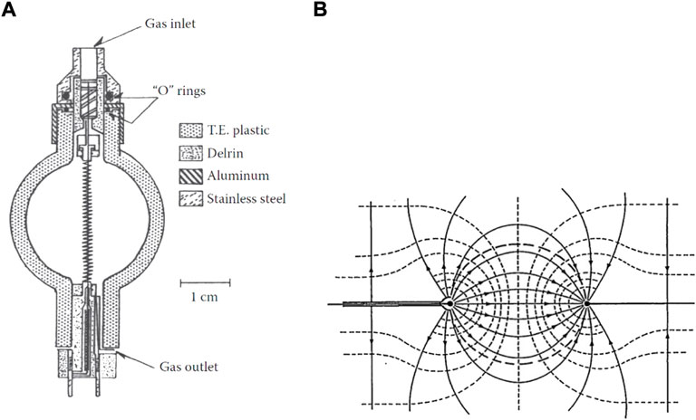
FIGURE 1. Solid-walled and wall-less TEPCs. (A) Cross-sectional view of a solid-walled spherical TEPC, showing the central anode wire, the helical grid, the chamber structure and gas flow fittings. Source: [6]. (B) Schematic of a wall-less TEPC representing the electric field lines responsible of defining the spherical collection volume. Source: [7].
TEPC detectors have millimetric sizes and simulate the micrometric tissue volume by controlling the gas pressure. If the gas and the simulated tissue target have the same atomic composition with the same atomic proportions, density differences could be reasonably neglected. The physical meaning of this assumption is that, under those conditions, a charged particle crossing the detector SV would interact with the same number and type of atoms in gas as it would in tissue. Typical pressure values to simulate a tissue sphere 1 µm in diameter range between 0.9 and 9.5 kPa. Gas-flow operation is often required to avoid gas contamination by atmospheric gases and water vapour permeating through the plastic wall. Different solutions have been proposed to maintain high gas purity also in those microdosimetry applications where gas-flow operation is unsuitable, like space applications, [7].
The three most commonly used counter-fill gases are methane-based TE-gas, propane-based TE-gas and pure propane. Their atomic composition is listed in Table 1, referring to ICRU data, [1]. For what concern the detector walls, A-150 plastic, which atomic composition is reported in Table 1 as well, is generally used instead.
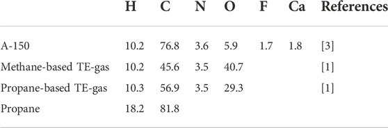
TABLE 1. Elemental composition in percent by weight of A-150 plastic and TE-gases commonly used in TEPC.
The application of a proper electric field within the gas volume allows the gas detector to work as a proportional counter. The electric potential is applied to the TEPC by using the wall as cathode and a central wire as anode. The central wire is placed from pole to pole or along the longitudinal axis in spherical or cylindrical detectors, respectively. Uniformity of the electric field, and hence of the gas gain, throughout the SV is an important requirement for the TEPC to give a uniform and homogeneous response. While in cylindrical detectors the electric field uniformity could be relatively easy to obtain by using field tubes, spherical detectors require a number of arrangements. Different laboratories have been working on improving the field uniformity in spherical TEPCs, and several solutions that allow to achieve acceptable results have been proposed, [8–10].
Some of the biggest problems of solid-walled TEPC are the so called wall-effects. They are the result of the difference in density between the solid wall and the low-pressure TE-gas. For a detailed explanation of wall effects, the reader is referred to [1, 3]. Wall effects do not affect the absorbed dose but they change the size of some individual energy deposition event, compromising the microdosimetric spectrum. As they can affect up to 10/20% of detected events [3], when a high level of accuracy is required, it becomes important to use wall-less counters. Wall effects are particularly important for high-energy protons and heavy ions, [7].
2.2 Conventional tissue equivalent proportional counter
Conventional TEPCs, which have long been commercialised, could be either solid-walled or wall-less detectors whose diameter usually ranges between 10 and 150 mm. Solid-walled TEPC are typically spherical or cylindrical shaped TE-plastic container, filled with TE-gas. Cylindrical detectors are easier to construct than spherical TEPC but their response is direction-dependent. This brings limitations to their use in isotropic fields and requires additional cares in the experimental set-up and in the mean path length estimation.
Both solid-wall and wall-less TEPC were successfully used to characterise different radiation fields and successfully applied to different radiation therapies, [11–27].
However, at very low pressures and high electric fields, the gas multiplication in the counter becomes dependent on the ionisation position, deteriorating the detector resolution. This limits the minimum site size that can be simulated by conventional TEPCs, preventing them to be used to simulate the volume of smaller cell structures like chromosomes and DNA strands.
2.3 Mini tissue equivalent proportional counter
The simulation of smaller site-sizes down to nanometric scale has been studied and successfully achieved by using a particular kind of TEPC called mini-TEPC, [28]. A cylindrical SV of 1 mm thickness and diameter is created into an A-150 plastic cylinder (13 mm in thickness and diameter) by drilling a 1 mm diameter cavity and by putting two Rexolite® cylindrical inserts on the two sides. The SV is therefore defined without the need of any field tubes. The anode wire is held in tension by a spring and passes through a hole drilled in the centre of the two inserts. The anode hole has a relatively large diameter of 150 µm to avoid the melting of the Rexolite® around caused by the electronic avalanche. The inserts and the A-150 plastic are held in position by other two Rexolite® cylinders and the whole device is enclosed in a 0.23 mm thick aluminium hollow cylinder for electromagnetic shielding. Figure 2A shows a schematic cross-section of the mini-TEPC described. While the mini-TEPC developed by De Nardo et al. [28] works in gas-flow mode, a more recent development of the mini-TEPC changed its operation in gas-steady mode, [29]. The gas and vacuum ducts were also modified to improve the counter cleaning from plastic degassing and the gas filling procedure. Besides allowing to simulate volumes down to nanometric scale, its reduced dimensions and fast time response allow to operate with fluence rate of the order of 106 cm−2 s−1 without major pile-up issues, which is another big advantage of the mini-TEPC on top of a conventional one.
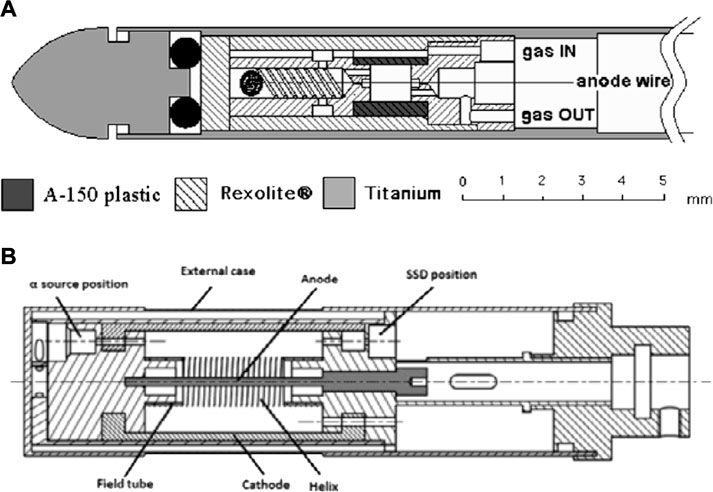
FIGURE 2. Schematic cross-section of a mini-TEPC and of the avalanche confinement TEPC. (A) Cut view of the mini-TEPC. Source: [28]. (B) Cross-sectional view of the avalanche-confinement TEPC. Source: [34].
The mini-TEPC proved to be a stable and reliable microdosimetry technology and it has been largely used for microdosimetry of clinical hadron therapy beams, [18, 28–33].
A mini-TEPC for Boron Neutron Capture Therapy (BNCT) microdosimetry was also developed: the twin miniaturised TEPC, [35]. It consists of two mini-TEPC contained into a cylindrical structure. One of the two mini-TEPCs’ wall is enriched in 10B to promote the boron neutron capture reaction.
2.4 Avalanche confinement tissue equivalent proportional counter
Based on the mini-TEPC design, a novel TEPC has been developed and studied: the avalanche confinement TEPC, [34, 36–38]. A schematic representation of the avalanche-confinement TEPC is shown in Figure 2B. The gas volume is subdivided into an external drift zone and an internal multiplication region where the electron multiplication avalanche is confined. Hence, a SV free of electron multiplication is created into the drift zone. This is achieved by using three independently biased electrodes: the central anode wire (graphite), the cylindrical cathode shell (A-150 plastic) and an additional helix (gold-plated tungsten). The additional helix is made of 19 coils with 6 mm diameter and it allows to confine the avalanche when properly biased. Two field tubes are used to sustain the helix and to define the SV, thus avoiding any distortion of the electric field. The device is designed with a thinner chamber wall to allow for high LET (Linear Energy Transfer) particles measurement. Eventually, the microdosimeter is equipped with a removable internal alpha source (244Cm) and a built-in solid state detector for energy calibration, [39]. The avalanche confinement TEPC operates in gas-flow mode, through a transportable vacuum and gas-flow system, and it is able to simulate site sizes in the range 300 nm–25 nm.
After preliminary measurements carried out in photon and neutron fields, the device was then used with proton, helium and carbon ions beams, showing promising results in agreement with Monte Carlo simulations, [34, 37, 40–42]. However, direct and systematic comparisons against a reference TEPC are still needed. In particular, the impact on the microdosimetric spectrum of those particles crossing the avalanche multiplication region between the helix and the anode (which volume makes the 20% of the total SV) needs to be assessed.
An accurate numerical model of the device was implemented by coupling a Monte Carlo code developed in MATLAB and a finite element analysis by means of COMSOL, [43]. While the first is used to simulate ionisation and electron scattering in the low-pressure TE-gas, the latter models the electric field and the electron avalanche inside the drift-region. When compared against experiments in several conditions, simulation results showed a good agreement, proving the reliability of the numerical model that could therefore be used to optimise the device design and its operation conditions.
3 Gas electrons multiplier
3.1 Working principles and general features
The concept of gas electrons multiplier was first introduced by Sauli in 1997, [44]. He proposed the GEM as a charge amplification device to couple with detection devices, such as gas detectors, to allow them to operate in less critical conditions while providing higher gains. GEMs are made of a thin insulating foil, typically around 50 µm thick, sandwiched in metal coats and with a high density of holes (usually 50–100 mm−2). The typical holes diameter is around 100 µm. By applying a voltage between the two sides, the electrons generated in the upper gas volume drift into the holes where they undergo multiplication and they are finally transferred to the bottom side where they can be collected or further amplified. Figures 3A,B show, respectively, an image taken at the microscope of a GEM foil and the electric field lines generated around GEM holes when a voltage is applied. Multiple GEM foils can be cascaded, allowing for higher gains with reduced applied voltages. This is particularly useful when dealing with highly ionising particles, that are likely to induce discharges when too high voltages are applied, [45]. Typical bias voltages for a conventional TEPC range around 600/800 V, while using a triple GEM for instance, voltages in the order of 300/450 V per GEM foil would be enough to obtained high operational gains. Another particularly interesting feature of GEM-based devices is that the SV, the multiplication region, and the readout board are geometrically and electrically separated, offering a higher stability of operation and a wide freedom in the readout pattern design.
FIGURE 3. GEM foil. (A) Electron microscope view of a GEM foil with holes with 70 µm diameter and 140 µm pitch. Source: [45]. (B) Simulated electric field in the GEM when a voltage is applied at its electrodes. Source: [46].
When coupled to a TEPC, the GEM could make a valid microdosimetry device. The application of GEM generally simplifies the construction of TEPC (by, for instance, eliminating the need of the central anode wire). The good outcome of first studies and tests of GEM-based detectors and their relatively simple design and construction, making them less expensive, easy to produce and very easy to adapt to different needs, allow GEM detectors to be a promising technology for microdosimetry.
3.2 Tissue equivalent proportional counter based on gas electrons multiplier
A GEM-based mini-TEPC was first proposed for microdosimetry by Farahmand in 2003 [47]. The device is a multi-element mini-TEPC working in gas-flow mode, coupled to a GEM detector. The device, whose structure is showed in Figure 4, consists of a read-out board, a Rexolite insulator layer, a GEM and an upper Rexolite insulator layer where five cylindrical SVs are drilled in. The read-out board has one anode-pixel per SV. Two additional pixels are included to account for the charge generated in the dead-space between GEM and read-out board. Anodes are all held at ground potential. The whole layered structure is sandwiched between two layers of tissue equivalent A-150 plastic, the upper working as a cathode (held at negative high potential).
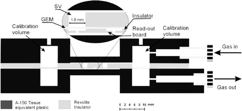
FIGURE 4. Schematic cross-sectional view of a GEM-based TEPC prototype. Only two out of the five sensitive volumes can be seen. Source: [48].
A different GEM-based mini-TEPC was designed and implemented by De Nardo et al. [49]. The device has 16 wall-less SVs, each 2 mm in thickness and diameter. SVs are defined by the strong electric field originated in the drift-region, which is the space between the upper cathode and the GEM, by the anode pads. The gas gain response obtained supported the use of pure propane gas (C3H8) instead of tissue-equivalent propane gas (TE–C3H8) for improved performances.
Both GEM-based mini-TEPCs were used in different neutron and photon fields, showing good results in agreement with reference TEPCs, [48, 50, 51].
3.3 GEMpix
An interesting novel GEM, the GEMpix, has been developed by CERN Radiation Protection Group, [52, 53]. GEMpix consists of a triple GEM [44], coupled to a quad Timepix ASIC readout system [54], with 262,144 pixels of 55 × 55 µm2 area each. Its pixelated readout system is able to measure both deposited energy and time of arrival in each pixel. Thanks to this feature, when coupled to a TEPC, the GEMpix proved its excellent particle tracking capability, [55]. Figure 5 shows four different events measured by the GEMpix in a protons-pions mixed beam with 120 GeV momenta, where the 3D path of the tracks measured by the detector were re-constructed. The track resolution was estimated to be about 170 μm, limited by the time measurement resolution (20 ns clock). The charge response of the pixels was found to be non-linear for low charges generated in the SV (low energy deposition events). Hence, an appropriate correction function has to be used. Improvements in terms of performances, such as a shorter time resolution improving the track resolution (up to a distance of the order of the pixel pitch) and a higher data throughput rate improving dead-time, are foreseen by the authors.
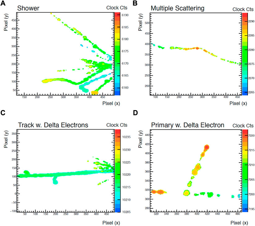
FIGURE 5. Examples of tracks measured by the GEMpix in its “time of arrival” mode: (A) shows a shower of secondaries, most likely originating in the TEPC wall, (B) shows a multiple scattering, (C) shows a densely ionised track (most likely a light ion) and delta electron emission, (D) shows a primary beam particle emitting an energetic delta-electron. Source: [55].
The GEMpix detector was successfully used to characterise a clinical carbon ion beam [56], measuring the 3D energy deposition spectra, 2D images of the beam, the Bragg curve and the 3D track paths. However, when comparing the measured dose against a reference dosimeter, significant differences up to 15% were found. A new, integrated system made of a dedicated water phantom housing the GEMpix-based TEPC and equipped with a reference ion chamber installed at the entrance window is under construction. Further microdosimetric experiments and cross-comparison with conventional microdosimeters are foreseen.
Thanks to its unique characteristics, the GEMpix-based TEPC sets as a very promising technology to be used as a novel particle tracker microdosimeter.
3.4 Thick gas electrons multiplier
An alternative GEM design is the thick GEM (TGEM), [58, 59]. TGEM differs from GEM for its size: the foil has millimetric thickness and holes diameter, both typically around 0.4 mm. TGEM manufacturing is therefore further simplified. A TGEM, for instance, could be manufactured using standard PCB (Printed Circuit Board) technology with precise drilling and Cu etching. Multi-element and multi-layered TGEM-based TEPCs for microdosimetry, whose typical structure is represented in Figure 6, have been developed and studied by several authors, [57, 60–64]. Mainly used in neutron and mixed neutron-gamma fields, the TGEM-based TEPC generally showed good agreement with conventional TEPC and consistent microdosimetric spectra. Further, improved detection efficiency up to a factor 3.0 ([62]) was observed for a multi-element TGEM with respect to a conventional TEPC. However, some spectra mismatch between TGEM and conventional TEPC ([63]) and severe angular dependence for neutrons with energy of the order of MeV or higher ([57]) were also found. Further investigations and developments are therefore still needed to improve TGEM accuracy and reliability.
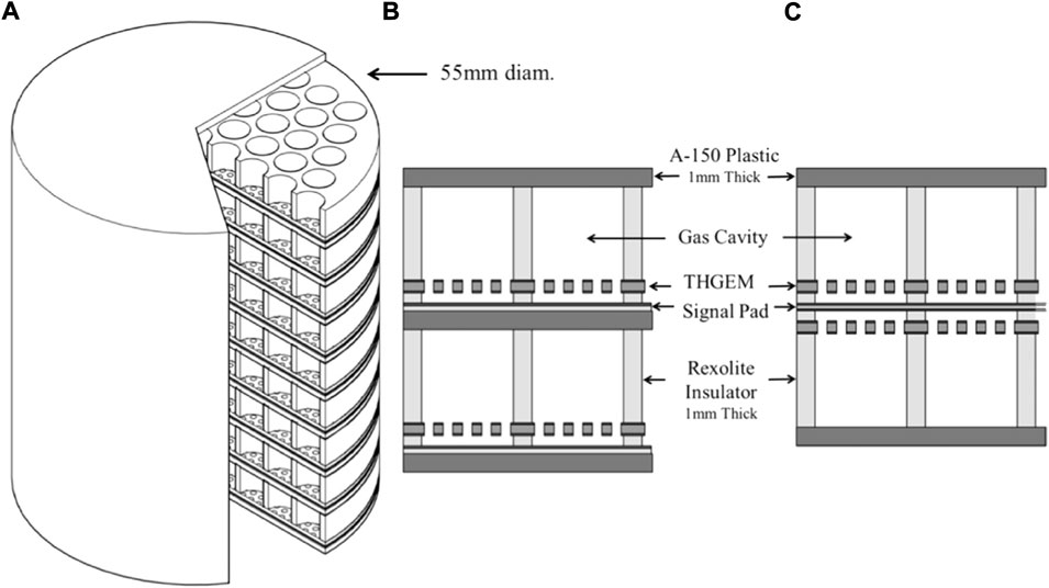
FIGURE 6. A 3D view of a 61 × 9 sensitive volumes TGEM-based TEPC (A), and schematic details of two different assembling option (B,C). Source: [57].
4 Solid state detectors
4.1 Working principles and general features
Solid-state detectors (SSDs) provide a valid alternative to TEPC as they avoid the contribution of wall-effects, they are compact, inexpensive, easy to transport and they have low power consumption and low sensitivity to vibrations, [65].
SSDs are mainly manufactured as p − n or p − i − n junctions, using one side of the p-n junction as blocking contact and the other as ohmic contact. p − i − n junctions are p − n junctions where the p and n regions are separated by an intrinsic region. An electric potential difference is naturally generated across the junction. The region where a potential difference exists is called depletion region. The presence of an electric field allows the electron-hole pairs generated by the ionising radiation to migrate towards the electrodes. This generates a current whose collection and integration gives rise to a pulse proportional to the energy deposited by the radiation. Thus, the SV of the detector coincides with its depletion region. With the application of an external higher voltage potential, the depletion region grows until the crystal is fully depleted (i.e., the depletion region extends over the whole crystal thickness).
One of the main limitations of SSDs is the electronic noise. Since no electron gain takes place in the detector itself, the noise level results in a worsening of the lowest energy that could be detected over the noise with respect to TEPC.
Microdosimetry by means of SSDs was first proposed and studied by Dicello et al. [66]. Since then, many solutions, mainly involving silicon-based and diamond-based detectors, have been proposed, studied and used. A number of requirements are needed for the good performances of a solid-state microdosimeter:
• a well-defined sensitive volume definition
• efficient charge collection
• accurate tissue-equivalent corrections
4.2 Silicon-based microdosimetry
Silicon-based detectors were the first solid-state microdosimeters studied by Dicello et al. [66].
Silicon-based microdosimeters are silicon p − n or p − i − n junctions with depletion thickness ranging between 1 and 10 μm, and typical sensitive areas around 10 × 10/100 × 100 µm2. Thanks to their micrometric size, silicon detectors can operate at full therapeutic beam intensities, whereas TEPC needs reduced beam intensity leading to more complicated and less clinical-representative measurements. Silicon-based detectors charge collection efficiency (CCE) is typically very high (around 100%). However, they suffer of the so called field funneling effect, [67]. The field funneling effect is a temporary local distortion of the electric field in the detector induced by the transit of high-LET particles. When the particle cross the detector, the electric field, that is normally limited to the depletion region, is observed to extend down into the detector substrate along the track of the particle, funneling a large number of carriers into the junction. This charge collection outside the depleted region hinders the definition of the SV. A solution to this problem is the use of silicon-on-insulator (SOI) devices [68]. This technique electrically insulates the SV, allowing to overcome the field funneling effect and to obtain well defined SVs. Silicon detectors can also be used for neutron detection by coupling them to or surrounding them by tissue-equivalent plastic (that would work as a neutron converter).
Modern silicon-based microdosimetry sees two major contributions: on one hand the more widely used technology developed by the Centre for Medical Radiation Physics (CMRP) at the University of Wollongong, and on the other hand the technology developed by the National Microelectronics Centre in Spain (IMB-CNM, CSIC).
Rosenfeld [69] described the development of CMRP’s silicon microdosimeters considering five generations of SOI arrays microdosimeters. The first three generations explored several solutions to eliminate charge sharing between adjacent SVs and to reduce charge collection via diffusion from outside the depletion region. The results were the fourth and fifth generations of silicon-microdosimeters, that represent the most accredited technology for what concern solid-state microdosimetry. The fourth generation detector, the 3D mesa “bridge” microdosimeter, was designed for low dose rate environments such as aviation and space and consists of a matrix of 4,248 well defined SVs of 30 × 30 × 10 µm3 each, creating a large overall sensitive area of 4.1 × 3.6 mm2. SVs are defined by fully etching a 10 µm thick layer of high resistivity n-type silicon. The sensitive layer stands on a low-resistivity supporting wafer consisting of a thin silicon oxide (SiO2) layer on a silicon substrate. The p − n junction structure is then produced by means of ion implantation. The device surface is eventually passivated thanks to a 1 µm thick over-layer of SiO2 and phosphorus silicate glass. Figure 7 shows a microscope picture of the 3D mesa bridge microdosimeter and a simplified representation of its structure. The SVs are connected in two parallel arrays, referred to as odd and even in Figure 7. Odd and even arrays are read out independently so that events in adjacent SVs are not read as one single event in case of obliquely charged particle tracks. A dedicated readout electronic probe (MicroPlus) was designed to optimise the device performances. The Silicon bridge microdosimetry system was able to measure lineal energies down to 0.2 keV μm−1 [70], making it an attractive alternative to TEPC also in terms of lower lineal energy cut-off. Ion Beam Induced Charge (IBIC) analysis showed an almost 100% CCE into the SVs. However, some lateral charge collection from outside the SVs was still observed from the bridge regions due to the high resistivity of n-silicon. To overcome the limitations of the fourth generation, a new 3D SOI microdosimeter, the mushroom microdosimeter, has been designed and implemented using 3D detector technology, [71]. This fifth generation detector is made of a matrix of well-defined cylindrical SVs with diameter and thickness of about 10 µm. The SVs are fabricated on a 2 µm thick SiO2 layer on a support handle silicon wafer. On each SV, cylindrical n+ columnar electrodes and surrounding p+ ring electrodes are produced by etching techniques followed by gas implantation. The whole ensemble of SVs will be embedded in PolyMethylMethAcrylate (PMMA). Figures 8A,B show, respectively, a schematic of the mushroom microdosimeter design and of its SVs structure. The mushroom microdosimeter is still in its development and optimisation phase, with different fabrication techniques being implemented and tested by means of IBIC analysis, [72–74]. Despite the good SV definition and the agreement, within the uncertainty, between measurements and simulations, low CCE regions were found within the central electrode and surrounding the SVs. Those regions create a low lineal-energy tail that compromises the measured spectrum. Monte Carlo simulations have also been carried out to optimise the new mushroom microdosimeter design, investigating the detector response both in aviation fields and in clinical proton and carbon ion beams, [75, 76].
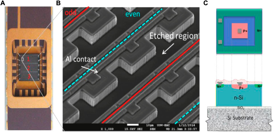
FIGURE 7. (A) A picture of a bridge microdosimeter mounted on a dual-in-line package; (B) a SEM (Scanning Electron Microscope) image of a fragment of the array of sensitive volumes; (C) simplified topology of the sensitive volume of the n-SOI bridge microdosimeter. Source: [69].
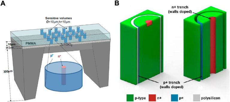
FIGURE 8. Schematic of the mushroom microdosimeter and of its sensitive volumes structure. (A) Schematic of the mushroom microdosimeter design. Source: [69]. (B) Schematics of two different configurations designed to define the sensitive volumes geometry and charge collection properties: a trenched planar structure on the left, and a Trenched 3-D structure on the right. Source: [72].
An overview of the IMB-CNM’s silicon-based microdosimetry technology can be found instead in the work of Guardiola et al. [77]. The first device, the ultra-thin 3D Si-detector, consisted of a matrix of columnar p-type and n-type electrodes fabricated into a SOI wafer, [78, 79]. The technology showed some main disadvantages when used as microdosimeter: the SVs were not completely defined, low CCE regions were found surrounding the SVs and inactive regions inside the detector were created by the electrodes columns. To improve the microdosimetric performances, a second device based on the 3D-cylindrical microdetector technology was designed and implemented, [80–82]. Quasi-toroidal trenches with typical inner diameters ranging from 9 to 25 µm are etched on a SOI wafer, defining the SVs in the enclosed cylindrical regions. Trenches are then filled with an internal n-type electrode layer edging the SV, followed by an external SiO2 isolation layer, as shown in Figure 9. A central p-type electrode is created into the upper crystal surface by boron implantation, allowing the detector to behave like a p-n junction. The SOI bulk wafer is eventually etched to match the buried electrode depth. A matrix of cylindrical SVs is created with typical thicknesses ranging between 5 and 20 µm. A dedicated front-end electronics, including high-pass and low-pass filters, was implemented to optimise detection performances. Connecting the n-electrodes to a common pad and the p + electrodes to individual read-out pads, each unit-cell of the matrix can be read individually. This allows to connect the read-out electronics in the most convenient configuration (individual SV reading, whole matrix, sub-groups of SVs) with respect to the experiment carried out. The pile-up can be reduced by using the individual SV reading when high fluence-rate are involved, whilst increasing the sensitive-area when dealing with low fluence-rates. Despite the significant improvement with respect to the ultra-thin 3D Si-detector, IBIC analysis showed the 3D-cylindrical microdetector was still affected by incomplete CCE regions near both n+ and p + contacts due to doping diffusion from the electrodes, [82]. A third generation microdosimeter was therefore designed and is currently under characterisation. The new device will be coupled to a customised portable multi-channel read-out system controlled by an automated software for real-time data analysis to provide an easy-to-use microdosimetry system for clinical applications.
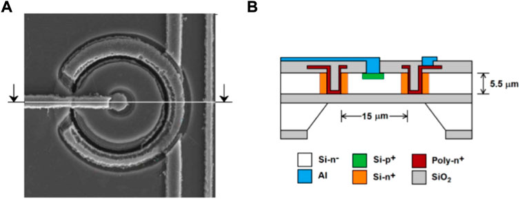
FIGURE 9. Front-face (A) and schematic representation of the cross-section (B) of a 3D-cylindrical microdetector unit-cell. Source: [83].
Silicon-based detectors proved to be a suitable and reliable technology for microdosimetry characterisation of therapeutic beams. They have indeed been successfully used to measure clinical hadron therapy beams, providing consistent results in agreement with both reference TEPC and Monte Carlo simulations. They also showed to be able to withstand clinical fluence rates without undergoing saturation effects or significant pile-up distortions. The ultra-thin 3D Si-detector was tested with 62 MeV protons and with 94.98 MeV/n C12 ions [84, 85], showing a relatively high lower energy threshold of 75 and 200 keV for protons and carbon ions, respectively. The 3D-cylindrical microdetector was tested, instead, on a 115.23 MeV/n C12 ion pencil beam at clinical fluence rate (5*107 s−1 cm−2), [83]. The SOI Bridge microdosimeter and the Mushroom microdosimeter were widely used to characterise a variety of therapeutic ion beams and to study and assess microdosimetric radiobiological models to estimate RBE. The two technologies have been compared in heavy ions beams of both low-energy [73], and therapeutic energy [86], giving good agreement between results. The mushroom microdosimeter was also used to characterise a 15 MeV proton beam [87], and several heavy ions beams from Helium to Neon, [72, 88, 89]. The bridge microdosimeter was used instead to characterise different clinical proton and carbon ion beams, [33, 90–93]. Finally, boron-coated silicon-based microdosimeters performances when applied to BNCT were studied by Bradley et al. [94], showing promising results in agreement with conventional gas-based neutron detectors.
4.3 Diamond-based microdosimetry
Diamond has been considered as an attractive alternative to silicon thanks to a number of interesting properties. It has a large bandgap allowing for small leakage current, high carrier mobility allowing for very fast time response (few nanoseconds), low dielectric constant so low capacitance, chemical inertness, blindness to visible wavelengths, high radiation hardness, good thermal stability and general stability of detector response, [95, 96]. Besides, diamond is fairly tissue-equivalent, making it particularly attractive for radiobiology and medical applications.
The interest in diamond detectors started growing with the improvement of homoepitaxially Chemical Vapor Deposition (CVD) growth techniques, which are able to provide reproducible high quality artificial diamond crystals in monocrystalline form at reasonable costs. The use of a CVD diamond for microdosimetry was first proposed and studied by Rollet et al. [97]. The feasibility of diamond-based detectors for microdosimetry was proved by their encouraging results. The development of diamond-based microdosimeters has seen, then, the efforts of three different institutes.
University of Roma Tor Vergata laboratories have been producing single-crystal CVD diamond detectors based on a multi-layered metal/nominal intrinsic/p-type structure working as a p − i − n junction, [98]. A conductive p-type boron-doped diamond layer is deposited by microwave plasma enhanced CVD on a commercial low-cost HPHT (high pressure high temperature) type diamond substrate. The p-type diamond layer is used as backing contact by creating an ohmic contact using annealed silver paint. Boron concentration is typically around 0.5*1020 cm−3. The intrinsic diamond layer, operating as SV, is then homoepitaxially grown on the p-type diamond. Its thickness can vary from about 1 µm to tens of µm. A thin metal electrode is eventually deposited on the intrinsic diamond surface by thermal evaporation, defining the detector sensitive area. Figure 10A shows a schematic representation of the CVD diamond detector described. Characterisation by means of IBIC and lateral IBIC analysis showed a well defined SV and a 100% CCE in the sensitive region without any incomplete CCE regions and any charge collection outside of the SV, [99, 100]. A variation of the fabrication technique has been recently studied by Verona et al. [101]. A similar p − i − n structure is obtained by means of both standard photolithography and selective CVD techniques to accurately define the micrometric SV. Figure 10B schematically represents the detector structure. IBIC analysis showed a well defined SV and a good uniformity of the CCE within the sensitive area. However, a thin region with lower CCE was found at the detector borders, generating a low energy tail in the measured spectra. The response of the detector showed good linearity with respect to the incident particle LET in the whole investigated range (100–3,000 keV μm−1). The low energy cut-off was around 80 keV.
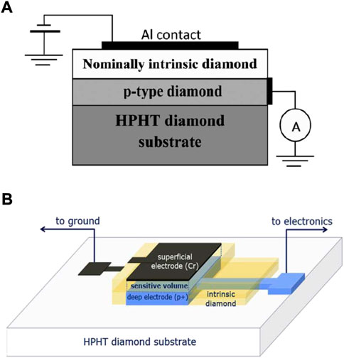
FIGURE 10. CVD diamond-based microdosimeter structure. (A) Structure of the CVD diamond based detector developed by the University of Roma Tor Vergata. Source: [98]. (B) Schematic representation of the diamond-based microdosimeter introduced by Verona et al. [101].
Alternative diamond-based microdosimeters have been developed by the Diamond Sensors Laboratory (LCD) of CEA, Saclay (France), [102]. Starting from a thicker intrinsic single-crystal CVD diamond from Element Six, 20/60 µm thick samples are sliced and polished. A thin p-type boron-doped diamond layer is then grown by CVD onto one of the surfaces of the intrinsic diamond. The structure is etched to its final thickness (<10 µm) by means of deep Ar/O2 plasma etching and the p-type layer is patterned to shape the sensitive areas by means of shallow Ar/O2 plasma etching using a metal mask. Finally, metal or carbon-based electrical contacts are deposited on the two sides of the membrane, creating a common full-pad electrode on one side, and an electrodes net (tracks, strips or pads) interconnecting the SVs on the other. As shown in Figure 11A, two different junction regions are created: a p-i-m junction below the boron-doped patterned layer defining the SVs, and a m-i-m all around. Without applying any bias, only the p-i-m region sees a built-in potential, thus allowing the device to operate correctly. Results of IBIC analysis performed on a 4 µm thick prototype showed the detector response was confined within the SVs, with complete 100% CCE for protons while reduced 80% CCE for carbon-ions as the built-in potential was not high enough to efficiently separate denser electron-hole pairs created by carbon-ions. The diamond detector showed excellent radiation hardness that would allow for over 500 hadron therapy treatments before a CCE drop of 1%. Nevertheless, an unexpected low-energy tail in the energy deposition spectra was found to be related to incomplete charge collection occurring close to the SV edges. To overcome the low-energy tail distortion and the lower CCE found for heavier ions, a novel approach using a guard-ring (GR) method was studied, [103]. Similarly to the previous technique, a thin membrane is obtained by deep Ar/O2 plasma etching from a single-crystal CVD diamond from Element Six. Thin Al electrodes are deposited on both side of the intrinsic diamond creating a m-i-m structure. Using a combination of laser photolithography and wet-etch process, an isolation trench on the metallic contact is created, resulting in the separation of a collection region and a GR region, as shown in Figure 11B. SVs are so created below the collection electrode when a voltage bias is applied. A 8 µm thick prototype with 10 µm wide isolation trenches was implemented and tested, showing well-defined SVs without any charge collection from the GR region. However, a region of incomplete CCE was still found at the SVs edges. Signals created below the isolation trench region are shared, indeed, between the collection and the GR electrodes. However, by reducing the isolation gap, the effect of the charge-sharing could be strongly reduced. This approach is a promising solution to get rid of, or at least strongly limit, the effects of the incomplete CCE region at the SV borders.
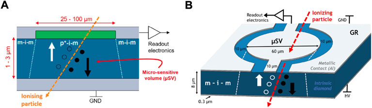
FIGURE 11. Detector structure of the diamond-based microdosimeters developed by CEA’s LCD. (A) Scheme of the double junction p-i-m/m-i-m diamond microdosimeter. Source: [102]. (B) Scheme of the Guard-Ring diamond microdosimeter. Source: [103].
Finally, the CMRP at the University of Wollongong has been developing diamond-based microdosimeters exploiting laser ablation techniques and Active Brazing Alloys (ABA) to create a matrix of isolated SVs in a high purity CVD diamond crystal from Element Six, [104–106]. Their latest development, the 3D Lateral Electrode Structure (3D-LES) detector, was implemented creating isolation trenches and two electrode-wells for each SV by means of laser ablation. Electrodes were then braised with silver ABA. A lateral electric field is therefore created between the two electrode wells, as shown in Figure 12. Despite the performance improvement with respect to previous generations, IBIC analysis showed that the 3D-LES detector was still affected by several problems. The conductive trench walls acted like virtual electrodes creating an additional component of electric field around the biased electrodes. Higher leakage current and a main electric field extending well below the electrodes depth were observed to degrade spatial resolution introducing low charge collection regions and to generate uncertainty on the effective SVs thickness. CMRP has now been putting its efforts in the development of a new diamond-based microdosimeter whose manufacturing combines the growth of a layered diamond structure, similar to the one developed by the University of Roma Tor Vergata and described above [98], with post-growth techniques such as laser ablation and ABA, [107].
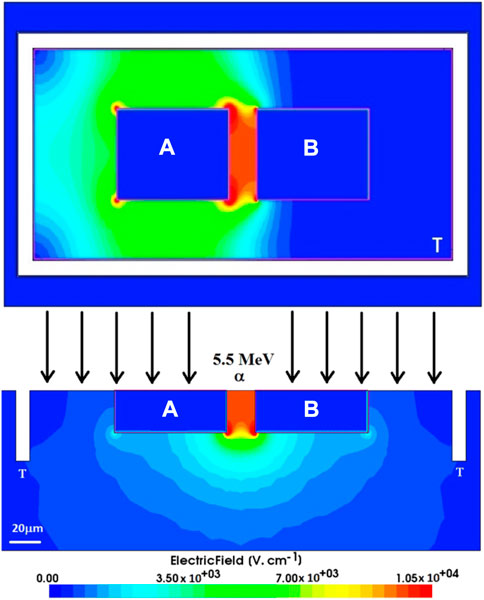
FIGURE 12. Top and cross-sectional view of simulated electric field distribution in the 3D-LES detector. A and B are the contact electrodes while T indicates the isolation trench (white region). Source: [106].
Application of CVD diamond microdosimeters to hadron therapy has been reported by Magrin et al. [108], who showed the suitability of diamond-based detector for microdosimetry of clinical carbon ion beams, and by Zahradnik et al. [102] and Verona et al. [109] who successfully used diamond-based microdosimeter with proton beams. A device consisting of a sandwich of two of these devices was also proposed as a detector for Boron Neutron Capture Therapy, using B10 in the boron-doped layer as neutron converter, [110].
4.4 ΔE − E telescope detectors
A very interesting and valuable alternative to single p-n or p-i-n junctions is the so called ΔE − E telescope detector. It consists of two stages of different thicknesses commonly named ΔE and E. The thinner ΔE, usually few µm in thickness, works as microdosimeter and it is followed by the thicker E stage, which measures the residual energy of the particle. The response of a telescope detector is therefore strongly direction-dependent, since a particle has to cross the ΔE first and successively the E to be properly detected. Whereas being ideal for directional beams like hadron therapy beams, telescopes fail in isotropic radiation fields.
When applied to microdosimetry, telescope detectors open up two main important possibilities. On one hand, telescopes could be used to identify the nature of the particle depositing energy, [111–117]. The ΔE-E scatter plot, representing the energy deposited in the ΔE stage against the energy deposited in the E stage, is a characteristic curve of the particle type. Hence, particle discrimination can be carried out, allowing for a comprehensive and precise characterisation of mixed-radiation fields. For instance, in the distal part of the Bragg Peak of a clinical ion beam, where the contribution of fragments is significant, the radiation quality assessment would strongly benefit from the combined information of microdosimetry and particle discrimination. On the other hand, by retrieving the total energy of the incident particle, summing the energy deposited in the ΔE and the residual energy measured by the E, the stopping power of the ion can be unequivocally determined. This information would allow an accurate conversion of the spectra measured by the detector into the equivalent spectra that would result in tissue or in a reference materials such as water. According to the method proposed by Agosteo et al. [65], for each detected event, the lineal energy measured by the ΔE stage is corrected by the ratio between the stopping power in the detector material and the stopping power in the reference material. However, both features would fail or be strongly limited if the detected particle was not stopping into the E stage, since the information on the incident particle energy would be missed. One of the critical aspects of a telescope detector is therefore its E stage thickness since it ultimately determines its optimal operational range.
Both silicon-based and diamond-based telescope microdosimeters have been reported in literature. They share a similar n-i-p-i-n structure consisting of a thin front-electrode, the ΔE sensitive volume about 2 µm thick, a 1/2 µm thick p-type layer creating a thin dead-layer between the two stages, the E sensitive volume about 500 µm thick and a thin back electrode. The highly doped p-type layer acts like a watershed separating charge collection between the two stages. Figure 13 shows a schematic of the two telescope microdosimeters.
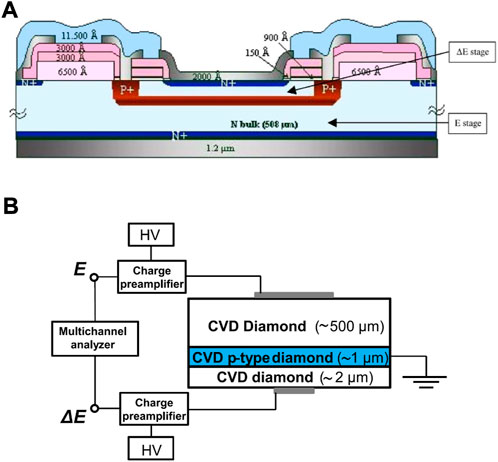
FIGURE 13. Silicon-based and diamond-based telescope structures. (A) Schematic representation of the silicon-based ΔE − E telescope microdosimeter. Source: [118]. (B) Schematic cross section view of the diamond-based telescope with indication of the read-out electronics. Source: [119].
The silicon-based telescope was first proposed by Tudisco et al. [120] and later developed and studied by Agosteo et al. [65, 118, 121–123]. The device was not affected by any field funneling effect and a low energy cut-off of 10 keV was achieved. The optimal design was found to be a pixelated ΔE stage on a common single E stage, that allowed to get rid of some geometrical effects observed with a single larger ΔE sensitive area (1 mm2). Each ΔE sensitive volume is surrounded by a guard-ring to confine the charge collection. IBIC analysis showed the charge collection was well confined within the guard-ring. However, an incomplete charge collection in the region between the pixel SV and the guard-ring was found to slightly distort the measured spectrum generating a low energy tail. The pixelated silicon-based telescope was used to carry out microdosimetry measurements of neutrons at different energies [124], and of different proton beams [65, 125, 126], showing good agreement when compared with reference TEPC. Finally, experiments with a 290 MeV/n carbon beam demonstrated the capability of the silicon telescope to discriminate the charged particles composing the mixed radiation field produced by carbon ions, while simultaneously measuring microdosimetric spectra, [127].
The diamond-based telescope has been implemented at University of Roma Tor Vergata, [119]. The E stage consists of a single crystal diamond from Element Six. Both the p-type boron-doped diamond layer and the intrinsic diamond ΔE are successively grown by Microwave Plasma Enhanced Chemical Vapour Deposition (MWPECVD) on the E stage and on the p-type layer, respectively. The telescope was fully characterised by means of IBIC analysis using microbeams of several low energy ions, [128]. A stable response was obtained, showing excellent linearity on a wide range of LET values (from 170 to 3,139 keV μm−1), good definition of SV and good homogeneity throughout the sensitive area. Further, its capability as a particle discriminator was proved. However, a cross-talk between the two stages was observed to affect the E stage response when the ratio of energy deposited in the E and in the ΔE was less than 1. A correction method was developed and further work to investigate and improve the cross-talk is foreseen. Experiments to use the diamond telescope in clinical proton and light ion beams are foreseen as well.
5 Hybrid microdosimetry
The development of a hybrid microdosimeter that puts together the advantages of different technologies is an interesting possibility that must be considered and studied. In this regard, Endo et al. [129] first proposed a detection system that couples a conventional TEPC to a pick-up scintillation counter (PSC), a 0.3 cm thick forward scintillation counter (FSC) and two 500 µm thick silicon detectors, SSD1 and SSD2. The PSC is to be placed in front of the water-equivalent phantom to monitor the total number of incident primary ions for spectra normalisation. The FSC and the two SSDs are placed instead behind the phantom but front the TEPC for particle identification. While the SSDs are used to identify charged particles, the FSC was designed to identify neutrons using a veto technique. The system was used with a clinical carbon ion beam and was able to measure the microdosimetric spectra of both primary carbon and secondary fragments by successfully discriminating the ion type. The FSC was not used during this first study.
An alternative hybrid design was proposed by Missiaggia et al. [130]: the Hybrid Detector for Microdosimetry (HDM). The HDM is a 2-stages detector consisting of a TEPC coupled to a silicon tracker-detector made of four Low Gain Avalanche Diodes (LGAD). The TEPC is used as the actual microdosimeter. The four LGADs, placed behind the TEPC, are each made of an array of 24 strips-shaped SVs and they are oriented both horizontally and vertically (2 and 2, respectively). Interpolating the detection positions in the four LGADs, the real track length of the charged particle in the TEPC can be re-constructed. The HDM would therefore open the possibility to perform a real track-length microdosimetry, putting aside the inaccuracy brought by defining the lineal energy on the mean chord length. Significant differences were found, indeed, between microdosimetric spectra obtained considering a mean chord length or a real track length lineal energy, with a general underestimation of the lineal energy if the mean chord length was used. High lineal energy events were the most affected since they are mainly caused by very high LET fragments whose path length is generally shorter than the mean chord length. However, an accurate track re-construction of these events can be very challenging. The feasibility of the HDM for microdosimetry was showed by studying its detection and tracking performances by means of particle tracking Monte Carlo simulations. Both proton and carbon ion beams were considered in the feasibility study. The low detection efficiency, since the particle has to cross all five detectors to be wholly detected, was identified by the authors as the main weak-point of the technology. Design adjustments, such as using thinner silicon detectors and optimising the inter-strip gaps, are foreseen to improve the detection efficiency. The possibility to use the HDM to discriminate the particle charge will also be investigated.
6 Microbolometer
In the framework of the development of a microdosimetry primary standard, a novel technology has been proposed and modelled by Galer et al. [131], and it is currently under development at NPL (National Physical Laboratories, United Kingdom). The device is based on a new type of transition edge sensor for particles detection: the inductive superconducting transition edge detector (ISTED) [132]. The ISTED is read out by a novel Superconducting QUantum Interference Device (SQUID), developed in a collaboration between NPL and University of Surrey, [133]. SQUID consists of a superconducting magnetic flux-quantising ring, whose diameter can vary from 100 µm down to 200 nm, interrupted by micro/nano-bridge Josephson junctions. A dual-absorber, consisting of a TE absorber (such as amorphous carbon) with cell or cell-nucleus dimensions and a superconducting absorber (such as Nb or Si), is deposited within the SQUID loop, so removing Johnson noise. When irradiated, each energy deposition event causes a temperature rise within the TE absorber volume. The heat is then conducted to the superconducting absorber, causing a change in its effective area which is detected by the SQUID as a voltage change. The SQUID response to temperature changes in the superconductive absorber was modelled by Hao et al. [132]. The device is therefore behaving like a micro-bolometer. This allows a direct measurement of the deposited energy, instead of the indirect information provided by the measurement of the ionisation produced, as in conventional gas and solid-state detectors. Ideally, the energy deposition would occur within the TE absorber alone. In a real scenario though, the superconductive absorber is also directly heated by the radiation and non-idealities in the heat transfer process affects the measurement as well. Corrections are therefore required. A method to calculate correction factors for non-idealities was implemented by Fathi et al. [134] by coupling particle tracking Monte Carlo simulations with heat transfer simulations for thermal analysis. Monte Carlo simulations were carried out by means of Geant4, while COMSOL was used to simulate the heat transfer. The authors modelled a 0.2 µm thick TE absorber film made of amorphous carbon on a 0.12 µm thick Niobium superconducting absorber film. The dual-absorber was built on a 360 µm thick silicon substrate. An environmental temperature of 6 K, at which the micro-bolometer performances are optimised, was considered. Correction factors for a 3.8 MeV proton pencil beam were estimated. A significant influence on the correction factors by the heat conducted from the silicon substrate was found. Further simulations are foreseen to thoroughly characterise the correction factors, especially for clinical ion beams.
Preliminary tests on a SQUID 15 µm in diameter, with a smaller Nb absorber layer inside the loop, showed a time response of few microseconds and an excellent energy resolution of about 0.2 eV, [131]. Nevertheless, a sharp rise in counts at low energies was observed even without irradiating the detector. The authors supposed the system detected the black-body infrared radiation emitted by the system hot end. The scatter contribution from the device areas around the absorber is believed to be another major challenge to overcome. The study and the development of new improved and optimised designs are foreseen.
The feasibility of the SQUID-based microbolometer for nanodosimetry was also studied, [135]. The study showed that the nanoSQUID could be able to detect events down to 10 eV.
Given the complexity and cost of the experimental set-up, which requires a liquid helium cryogenic system to keep the operational temperature at around 6 K, the SQUID-based microbolometer is unsuitable to be used in clinical environment. Nevertheless, its promising performances and its potentially extreme accuracy place it in first line towards the realisation of a microdosimetry primary standard.
7 Discussion
The development of detectors for microdosimetry is an active field of research, with an increasing quantity of new and promising technological solutions being studied and characterised. Currently, a best microdosimeter cannot be identified, at least in absolute terms. Different detectors have different advantages and drawbacks and their performances are significantly related to the application they are used for.
7.1 Summary and general comparison
TEPC is the most widely used and affirmed technology. As also concluded by Agosteo [136], it can be considered the reference standard for microdosimetry, especially when new devices are characterised. Indeed, its sensitive volume material is tissue-equivalent and it can detect on the widest (between the current microdosimetry technologies) range of lineal energy down to few 100 s eV µm−1. The price is a very complex system, requiring high-voltage supply, vacuum containment and pump, pressure control and, for some of them, a gas flowing system. This makes TEPC impractical in many experimental conditions. A part from wall-less detectors, TEPC is also affected by wall-effects due to the large density difference between plastic wall and low pressure gas. Wall-effects can distort the microdosimetric spectra measured. As a final (but not less important) drawback, its relatively big size significantly limits TEPC performances when high spatial resolution is required, where steep stopping power gradients exist and at high fluence-rates. In this regard, mini-TEPC significantly improves size-related drawbacks without loosing TEPC advantages. Nevertheless, mini-TEPC still results in worse spatial resolution and worse performances at high fluence rates than SSDs.
An alternative to the conventional TEPC is the GEM-based TEPC. GEM significantly simplifies the detector design and construction, lowering its cost that, given the complexity of a TEPC system, is generally very high. The GEM-based TEPC has the additional advantage of having the detection volume, the multiplication region, and the read-out board geometrically and electronically separated. Further, its design can be easily adapted to different experimental conditions and it allows a potentially useful freedom in the read-out pattern design. However, the SV definition is worse than conventional TEPC as electron-ion pairs generated in regions outside the SV could be sometimes collected. Between the GEM-based TEPC, the GEMpix stands particularly out thanks to its particle tracking capability allowing it to carry out particle-tracking microdosimetry. The current limitations brought by its relatively big size, and the huge amount of information resulting from a GEM-pix measurement, complicate its use in clinical practice. However, its unique features can be extremely useful in many microdosimetric studies.
On the other hand, SSDs showed excellent performances too, solving most of TEPC issues but showing other drawbacks instead. Their actual micrometric size allows for high spatial resolution both in the beam direction and transverse to it. An accurate characterisation of the radiation field even in presence of steep stopping power gradients, as those found around a typical ion Bragg peak, is therefore possible. Their fast time-response and their versatility in being manufactured as stand-alone detectors or as multiple-detectors assemblies allow them to operate at any fluence rate condition. However, their SV is not tissue-equivalent and corrections have to be applied to measured data, introducing uncertainties. Even though the energy resolution is improved, the lower energy cut-off is worsened (worse signal to noise ratio), making SSDs blind to very low lineal energies. As pointed out by Bianchi et al. [137] and discussed better in the next section, this could have a significant impact in certain conditions. Hence, this limit must be well assessed before using a SSD for microdosimetry. Further, a small region edging the SV and collecting charge with reduced CCE was observed in most of solid-state microdosimeters. The origin of this effect was suggested to be either a partial extension of the electric-field outside the SV or the collection of charge carriers getting into the SV by drift diffusion from outside. However, a systematic characterisation of the effect and of its impact on the final microdosimetric spectrum is still missing. Finally, SSDs response is not isotropic and it could be strongly affected by the radiation incident direction. Whilst not being a problem for uni-directional radiation beams, this could compromise the measurement when isotropic radiation fields are involved.
The use of two-stages telescope detectors can bring additional value to solid-state microdosimetry. Even though the telescope operability is restricted to directional beams, it maintains all the features of a SSD, while adding two important advantages:
• the possibility to know the energy of the impinging particle, thus simplifying and improving material corrections;
• the possibility to discriminate the type of particle detected, that would strongly improve the radiation quality characterisation.
Hybrid microdosimeters have eventually been proposed and studied, proving their feasibility to discriminate the particle detected and to perform real-track length microdosimetry, where the real particle track into the SV can be reconstructed. Despite still being in a development stage, their promising features and first measurements make them an attractive technological solution.
Finally, the SQUID-based microbolometer is a novel microdosimetry technology in its early stage of development. Its performances are extremely promising. Given the complexity and cost of the system and of its operational conditions though, its clinical use in hadron therapy would be unsuitable. Nonetheless, the motivation behind its development is the creation of a microdosimetry primary standard, whose characteristics could be fulfilled by the microbolometer.
7.2 Notes on data analysis
Two approaches for microdosimetry data analysis have been proposed: a pulse height analysis (PHA) based approach and an approach based on variance analysis. For a detailed description of microdosimetric data analysis methods, the reader is again referred to the text book by Lindborg and Waker [3]. Only a general idea of the PHA approach, which is the most widely and commonly used, is provided in this text for the understanding of the following discussion. Even if a general common data analysis method for microdosimetry could be identified, each technology, with its peculiarities, requires specific needs and cares.
The actual physical quantity measured by a microdosimeter is the ionisation generated by each particle or photon crossing the detector SV and depositing energy. The ionisation produces free charge carriers whose collection generates current pulses. The use of a charge-sensitive preamplifier allows to convert the current pulses in amplified voltage pulses, while maintaining a proportionality with the energy deposition. An energy calibration is therefore possible. From geometrical considerations, the mean chord length is estimated and the lineal energy of each event is then calculated. Microdosimetric distributions and mean values are hence calculated. Two keys steps could be identified in the analysis: the calibration in lineal energy, which is the most critical one, and the conversion of the measured data into their equivalent in some reference material (i.e., water or tissue).
The calibration in lineal energy could be seen as the combination of the actual calibration in energy between the voltage pulses and the deposited energy values, and of the information on the mean chord length. The most commonly used method is the edge method. It consists in identifying what is called a particle-edge (e.g., proton-edge, carbon-edge, … ) on the measured spectrum and in calculating the calibration coefficient considering the particle-edge definition: the maximum energy that the particle could deposit into the detector SV. The benefits of using the particle-edge calibration method are undoubtedly related to the fact that it relies on a spectrum structure. Hence:
• it is usually a reliable and stable reference point;
• it is usually embedded in the measurement itself and so it does not require a dedicated measurement;
• it is an on-field calibration carried out in the same experimental conditions as the experiment itself, and with the same particle detected (hence no needs of conversion factors to account for potential differences in ionisation energy between the radiation modality used for the calibration and the one measured during the experiment);
• it is based on a physical parameter so it does not depend on any additional device or beam information.
The edge method suffers of three main sources of uncertainty:
• the choice of the point of the spectrum to consider as the actual particle-edge and its estimation;
• the uncertainty of the stopping power values used for the calculation of its nominal value;
• the geometrical information needed for its calculation.
The first two sources of uncertainty have been studied and assessed by different authors, [138–140]. They suggested an optimal methodology and proved that the proton-edge could be successfully used for lineal energy calibration with an uncertainty below 5%. The geometrical information needed for the calculation of the particle-edge nominal value is the longest chord travelled by the particle into the detector. Its value depends on the radiation field (i.e., isotropic or directional) and on the detector geometry. In hadron therapy, for instance, the radiation field is a strictly directional particle beam. The longest chord for spherical and cylindrical (with axis perpendicular to the beam direction) detectors is therefore their diameter, while it is the thickness for slab and cylindrical (with axis parallel to the beam direction) detectors. The uncertainty is therefore that of the detector thickness or diameter. For a TEPC-based microdosimeter, this uncertainty is then related to the gas density uncertainty and it is usually reasonably low. For SSD instead, their thickness uncertainty depends on the manufacturing process (for instance, on the accuracy of the relation between time of growth and thickness grown) and it is usually a significant uncertainty (10/20%). A dedicated measurement of the detector thickness is therefore recommended.
The uncertainty of the mean chord length is also contributing to the overall calibration uncertainty. Since the use of the mean chord length in the definition of lineal energy is matter for debate, a dedicated discussion was considered desirable. According to the original and official lineal energy definition by ICRU [1], the lineal energy is defined on the mean chord length: the mean length of randomly oriented chords in the volume. For a convex body, that is
The choice of the geometrical quantity to be considered in the definition of lineal energy is still an open debate among the microdosimetry community. Coming to an agreement will be fundamental, particularly if different microdosimeters are to be used in combination or compared.
Moving to the material conversion, as for conventional dosimetry, this process is needed to standardise measurement results when different detectors could be employed. Besides, when microdosimetry is applied to radiobiology, material conversion is required to take into account the differences between the radiation interaction with the detector material and with the biological tissue. Different techniques have been proposed in literature, from using a single or multiple conversion factors [141–143] to convert each lineal energy event with the ratio of the stopping power in the two materials [65, 144]. However, a systematic comparison between the different methods to study their reliability and accuracy is still missing. None of the methods proposed so far takes into consideration the contribution of secondary fragments. Since they are usually different ion species with respect to the primary, the material conversion is not straight forward and dedicated models should be implemented. An accurate consideration of secondary fragments events in the material conversion is important, as particles generated by nuclear interactions can have a major impact on microdosimetric quantities and uncertainty, [145]. The material conversion uncertainty mainly depends on the method employed and on the detector material. In general, the uncertainty increases as the detector material differs from tissue. In this regard, TEPC is the optimal solution, while diamond, being made of carbon atoms, offers a reasonable solution between SSDs.
A final note should be made on the lineal energy range measured by a detector. Ideally, the whole lineal energy spectrum from 0 to inf keV μm−1 should be measured. Real detectors, however, have detection limits on both sides. A low lineal energy threshold exists because of electronic noise and external disturbances. Its effect on microdosimetric quantities was studied by Bianchi et al. [137]. The low lineal energy threshold mostly affects particle beams with very low LET, whose microdosimetric spectra sits at very low lineal energies and a significant part could be lost. For instance, a clinical proton beam at the entrance region would be highly affected. However, as the microdosimetric spectrum shifts to higher lineal energy regions, the impact of the low lineal energy threshold becomes less and less significant until becoming negligible. TEPC-based detectors offer again an optimal solution as their low lineal energy threshold around 0.1/1 keV μm−1 is the lowest achieved so far. Nevertheless, SSDs performances are improving fast and thresholds of few keV μm−1 have already been obtained. Such thresholds guarantee reliable operation with low impact over most clinical conditions. On the other hand, the high lineal energy limit is more an overlooking in the experimental practice than a technological limit. Nuclear interactions of high energy protons and ions with target material could result in the production of low energy fragments with very high LET, [146]. This is particularly true for protons, whose fragments are mainly target fragments with higher atomic number. As pointed out by Parisi et al. [145], events related to nuclear interactions have a huge impact on microdosimetric quantities, such as the mean dose lineal energy, and on their uncertainty. However, it is very challenging to properly take them into account. They are indeed very rare events, with lineal energy values which are orders of magnitude higher than the maximum value usually expected (the ion-edge). They are therefore often overlooked. The first step should be their proper investigation, that would bring possible technological challenges up. As already common practice for TEPC, the simultaneous use of different shaping amplifiers with different gains, and the convolution of the resulting spectra, allows to detect on a wide lineal energy range without losing resolution. Additional care should be put in the choice of the charge sensitive preamplifier, that should not saturate even for very high energy deposition events (up to several tens of MeV). Possible technological challenges restrict, therefore, to the detector response to such highly ionising events.
7.3 Experimental cross-comparison
A systematic cross-comparison between different technologies in different experimental conditions will be a fundamental step towards the identification of microdosimetry standards and code of practice. First works of this kind have recently been carried out by different authors. A mini-TEPC, a GEM-based TEPC, a silicon-based telescope, and a diamond-based microdosimeter were compared under a 62 MeV/n clinical carbon beam, [147]. A 62 MeV clinical proton beam was used, instead, to compare a mini-TEPC and a silicon-based telescope [148], and to compare a mini-TEPC and a silicon-based bridge microdosimeter, [33]. Significant differences in the microdosimetric spectra were observed between different detectors. These were mainly attributed to the effects of detector thickness and to wall effects. While the first were prevalent on and beyond the Bragg peak region where the energy of the incident ions was lower, the latter were prevalent in the entrance region. Nevertheless, in terms of mean lineal energy values and evaluated RBE, an agreement within the uncertainties between the different detectors was reported in all mentioned works. The highest data dispersion occurred in the distal edge of the Bragg peak. The difference in low lineal energy cut-off between different technologies was found to give a negligible contribution to the mean dose lineal energy variation. This was mainly influenced by the calibration uncertainty and by the uncertainty in material corrections instead. A comprehensive, systematic and methodical uncertainty analysis, which is missing in literature at date, would be helpful to obtain improved and more accurate comparisons in future. First interesting works pointing towards this direction have been recently carried out by Hartzell et al. [149], and by Meouchi et al., [150].
7.4 Hadron therapy focused considerations
Focusing on the hadron therapy application, a complex experimental scenario is to be dealt with. High fluence rates of the order of 107 cm−2 s−1 are usually delivered, making conventional TEPC unsuitable to operate with full clinical fluence rate. Mini-TEPC or SSDs, that showed to be able to operate at such fluence-rate or slightly below, are therefore advised. Besides, hadron therapy delivers protons or light ions (mainly carbon ions) at very high initial energies, so to be able to hit the cancer region, in particular for deep-seated tumours. By slowing down, the particles strongly change their energy and stopping power along their path. Thus, lineal energy spectra could differ orders of magnitude between entrance and final part of their path. In particular, around the Bragg peak region, very steep lineal energy gradients are found. A high enough spatial resolution is therefore needed to properly characterise the peak region. This is of fundamental importance as, if the Bragg peak region of the particle beam is well characterised, the treatment will be extremely effective in damaging cancer cells and spearing healthy tissues. A non-accurate characterisation and planning, on the other hand, would bring severe damages to healthy tissues. In this regard, and considering their relatively simple set-up and operation, SSDs seem to be the most indicated for hadron therapy applications. However, if the detector thickness is too large, microdosimetric spectra on and beyond the Bragg peak (characterised by lower incident energies, hence higher lineal energies and shorter particle range) will be distorted by all those particle stopping within the SV. Mean lineal energy and RBE values will be compromised as well. On the other hand, if the detector is too thin, the low lineal energy cut-off will be too high to properly detect the microdosimetric spectra in the entrance region (characterised by higher incident energies, hence lower lineal energies). This is particularly critical for protons whose stopping power gets down to few keV μm−1. A careful assessment of the detector thickness is therefore required. The development and employment of multi-thickness SSDs could be an interesting and neat solution.
Another important aspect to consider when thinking of microdosimetry in hadron therapy practice is the radiation damage to the detector. Radiation damage mainly concerns SSDs and it may affect microdosimetric results, and hence the QA and the RBE estimates. Its dependence on many factors (non-ionising energy loss, dose rate, LET, type of particle, temperature, etc.) makes it difficult to take into account in practice. A good radiation hardness is therefore fundamental to guarantee a reliable operation over time. With respect to radiation damage, diamond-based detectors offer a better solution than silicon-based detectors. Even though Zamboni et al. [151], found that for very low energy ions (0.5 MeV/n) silicon is more radiation tolerant than diamond, according to de Boer et al. [152], diamond has a higher radiation hardness than silicon in the clinical energy range. Considering protons, for instance, diamond would be from 2/3 times more resistant than silicon at around 10 MeV, to 5/10 times more resistant around and above 100 MeV. Further, thin diamond-detectors with p-i-n junction structures, as those used for microdosimetry, were found to be even more performing in terms of radiation tolerance than metal-intrinsic-metal diamond detectors, [100]. Reporting the results of Verona et al. [100], after a dose corresponding to about two thousand full treatments, the CCE is expected to decrease of just 1%. Radiation damage does not hinder the use of SSDs for microdosimetry of hadron therapy beams and their use in clinical practice. However, a periodic calibration of the microdosimeter will be required with higher frequency than what commonly required in clinic for conventional dosimeter such as ionisation chambers.
Finally, material corrections are needed for SSDs, increasing measurement uncertainty. The criticality of the material conversion around the Bragg Peak region, where LET and RBE are the highest, is here stressed, in particular for silicon-based detector. The assessment of the reliability and accuracy of existing methods will be fundamental to properly assess final uncertainties and to develop an optimised material conversion method.
The identification of a reference microdosimeter for hadron therapy applications is therefore an unresolved and complex matter. Table 2 aims to schematically summarise benefits and limitations of the main microdosimetry technologies. The combined use of different technologies must be considered, since it would allow to benefit from their different advantages and compensate for each other drawbacks. For instance, a microdosimetry system could be made of:
• a mini-TEPC to characterise the entrance region and to provide a reference for tissue-equivalence corrections;
• a thin SSD to characterise the Bragg peak region and its distal part, with their steep gradients and with the presence of secondary fragments;
• a thicker SSD to obtain spectra down to lower lineal energy values, allowing an accurate characterisation of the plateau region, whose lineal energy gradients could be noticeable (in particular for heavier ions).
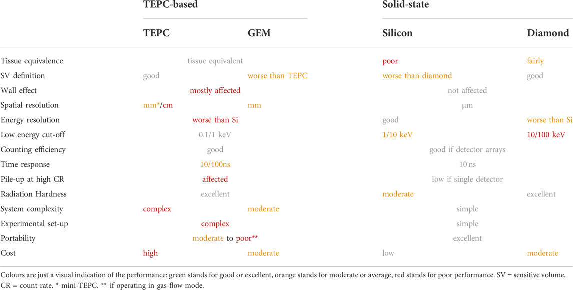
TABLE 2. Qualitative summary of advantages and drawbacks of the main microdosimetry technologies in terms of performances.
Such a system would provide good continuity and accuracy along the whole depth-dose profile, overcoming most of the drawbacks of a single detector alone. Thus, it would allow a comprehensive and reliable microdosimetric characterisation of any clinical beam.
8 Conclusive remarks
The quite large variety of microdosimetry technologies made the application of microdosimetry suitable to many different fields. The study and use of microdosimetry for radiobiology, hadron therapy, BNCT, radiation protection and aviation and space applications have indeed been reported in literature. However, fragmented research and technology development have slowed down the assessment and implementation of microdosimetry standards and accepted protocols and procedures. These are indeed still missing, but they are fundamental for the transition towards a clinical or official use of microdosimetry in any of its fields of application. Research works and experiments should be carried out aiming at conveying to a rigorous assessment of existing techniques, experimental methods, and reference conditions. This would result in the development of a strong methodology involving all technologies under study.
Author contributions
GP contributed to the investigation, methodology, conceptualisation and manuscript writing. GS and FR supervised the work.
Funding
This work was funded by EPSRC industrial CASE award. The open access publication of this work was supported by the University of Surrey.
Conflict of interest
The authors declare that the research was conducted in the absence of any commercial or financial relationships that could be construed as a potential conflict of interest.
Publisher’s note
All claims expressed in this article are solely those of the authors and do not necessarily represent those of their affiliated organizations, or those of the publisher, the editors and the reviewers. Any product that may be evaluated in this article, or claim that may be made by its manufacturer, is not guaranteed or endorsed by the publisher.
References
1. Booz J, Braby L, Coyne J, Kliauga P, Lindborg L, Menzel HG, et al. ICRU report 36: Microdosimetry. J Int Comm Radiat Units Measurements os19 (1983) 1. doi:10.1093/jicru/os19.1.Report36
3. Lindborg L, Waker A. Microdosimetry. In: Experimental methods and applications (2017). doi:10.1201/9781315373737
4. Rossi HH, Rosenzweig W. A device for the measurement of dose as a function of specific ionization. Radiology (1955) 64(3):404–11. doi:10.1148/64.3.404
5. Glass WA, Gross W. Wall-less detectors in microdosimetry. Cambridge, United States: Academic-Press (1972).
7. Braby LA. Experimental microdosimetry: History, applications and recent technical advances. Radiat Prot Dosimetry (2015) 166(1-4):3–9. doi:10.1093/rpd/ncv137
8. Benjamin PW, Kemshall CD, Redfearn J. A high resolution spherical proportional counter. Nucl Instr Methods (1968) 59(1):77–85. doi:10.1016/0029-554x(68)90347-9
9. Waker AJ. An investigation of the characteristics of a spherical single-wire proportional counter used for experimental microdosimetry. Nucl Instr Methods Phys Res Section A: Acc Spectrometers, Detectors Associated Equipment (1986) 243:561–6. doi:10.1016/0168-9002(86)90995-2
10. Perez-Nunez D, Braby LA. Replacement tissue-equivalent proportional counter for the international space station. Radiat Prot Dosimetry (2010) 143(2-4):394–7. doi:10.1093/rpd/ncq409
11. Kliauga PJ, Colvett RD, Lam YMP, Rossi HH. The relative biological effectiveness of 160 MeV protons. I. Microdosimetry. Int J Radiat Oncology*Biology*Physics (1978) 4(11-12):1001–8. doi:10.1016/0360-3016(78)90012-3
12. Kliauga P, Dvorak R. Microdosimetric measurements of ionization by monoenergetic photons. Radiat Res (1978) 73:1. doi:10.2307/3574570
13. Amols HI, Bradbury JN, Dicello JF, Helland JA, Kligerman MM, Lane TF, et al. Dose outside the treatment volume for irradiation with negative pions. Phys Med Biol (1978) 23(3):002–96. doi:10.1088/0031-9155/23/3/002
14. Metting NF, Rossi HH, Braby LA, Kliauga PJ, Howard J, Zaider M, et al. Microdosimetry near the trajectory of high-energy heavy ions. Radiat Res (1988) 116:183. doi:10.2307/3577456
15. Menzel HG, Lindborg L, Schmitz T, Schuhmacher H, Waker A. Intercomparison of dose equivalent meters based on microdosimetric techniques: Detailed analysis and conclusions. Radiat Prot Dosimetry (1989) 29(1-2):55–68. doi:10.1093/oxfordjournals.rpd.a080530
16. Pihet P, Menzel H, Schmidt R, Beauduin M, Wambersie A. Biological weighting function for RBE specification of neutron therapy beams. Intercomparison of 9 European centres. Radiat Prot Dosimetry (1990) 31(1-4):437–42. doi:10.1093/oxfordjournals.rpd.a080709
17. Loncol T, Cosgrove V, Denis J, Gueulette J, Mazal A, Menzel H, et al. Radiobiological effectiveness of radiation beams with broad LET spectra: Microdosimetric analysis using biological weighting functions. Radiat Prot Dosimetry (1994) 52(1-4):347–52. doi:10.1093/rpd/52.1-4.347
18. Srdoč D, Stephen A, Srdoc D. Microdosimetry of monoenergetic neutrons. Radiat Res (1996) 146:466. doi:10.2307/3579309
19. Tilikidis A, Lind B, Nafstadius P, Brahme A. An estimation of the relative biological effectiveness of 50 MV bremsstrahlung beams by microdosimetric techniques. Phys Med Biol (1996) 41(1):55–69. doi:10.1088/0031-9155/41/1/005
20. Gerlach R, Roos H, Kellerer AM. Heavy ion RBE and microdosimetric spectra. Radiat Prot Dosimetry (2002) 99(1-4):413–8. doi:10.1093/oxfordjournals.rpd.a006821
21. Endo S, Onizuka Y, Ishikawa M, Takada M, Sakurai Y, Kobayashi T, et al. Microdosimetry of neutron field for boron neutron capture therapy at Kyoto University reactor. Radiat Prot Dosimetry (2004) 110(1- 4):641–4. doi:10.1093/rpd/nch150
22. Rollet S, Autischer M, Beck P, Latocha M. Measurement and simulation of lineal energy distribution at the CERN high energy facility with a tissue equivalent proportional counter. Radiat Prot Dosimetry (2007) 125:1425–88. doi:10.1093/rpd/ncl554
23. Taddei PJ, Zhao Z, Borak TB. A comparison of the measured responses of a tissue-equivalent proportional counter to high energy heavy (HZE) particles and those simulated using the Geant4 Monte Carlo code. Radiat Meas (2008) 43:91498–5051505. doi:10.1016/j.radmeas.2008.09.003
24. Martino G, Durante M, Schardt D. Microdosimetry measurements characterizing the radiation fields of 300 MeV/u 12C and 185 MeV/u 7Li pencil beams stopping in water. Phys Med Biol (2010) 55(12):3441–9. doi:10.1088/0031-9155/55/12/011
25. Dicello JF, Gersey BB, Gridley DS, Coutrakon GB, Lesyna D, Pisacane VL, et al. Microdosimetric comparison of scanned and conventional proton beams used in radiation therapy. Radiat Prot Dosimetry (2011) 143(2-4):513–8. doi:10.1093/rpd/ncq513
26. Rollet S, Colautti P, Grosswendt B, Herault J, Wind M, Gargioni E, et al. Microdosimetric assessment of the radiation quality of a therapeutic proton beam: Comparison between numerical simulation and experimental measurements. Radiat Prot Dosimetry (2011) 143(2-4):445–9. doi:10.1093/rpd/ncq483
27. Al-Bayati SN. The application of experimental microdosimetry to mixed-field neutron-gamma dosimetry” (2012). Thesis.
28. De Nardo L. Mini-TEPCs for radiation therapy. Radiat Prot Dosimetry (2004) 108(4):345–52. doi:10.1093/rpd/nch023
29. Conte V, Bianchi A, Selva A, Petringa G, Cirrone G, Parisi A, et al. Microdosimetry at the CATANA 62MeV proton beam with a sealed miniaturized TEPC. Physica Med (2019) 64:114–22. doi:10.1016/j.ejmp.2019.06.011
30. Moro D, Colautti P, Lollo M, Esposito J, Conte V, De Nardo L, et al. BNCT dosimetry performed with a mini twin tissueequivalent proportional counters (TEPC). Appl Radiat Isot (2009) 67(1):S171–4. doi:10.1016/j.apradiso.2009.03.042
31. De Nardo L, Colautti P, Herault J, Conte V, Moro D. Microdosimetric characterisation of a therapeutic proton beam used for conjunctival melanoma treatments. Radiat Measurements (2010) 45(10):1387–90. doi:10.1016/j.radmeas.2010.05.034
32. Colautti P, Conte V, Selva A, Chiriotti S, Pola A, Bortot D, et al. Microdosimetric study at the cnao active-scanning carbon-ion beam. Radiat Prot Dosimetry (2018) 180(1-4):157–61. doi:10.1093/rpd/ncx217
33. Conte V, Agosteo S, Bianchi A, Bolst D, Bortot D, Catalano R, et al. Microdosimetry of a therapeutic proton beam with a mini-TEPC and a MicroPlus-Bridge detector for RBE assessment. Phys Med Biol (2020) 65:245018. doi:10.1088/1361-6560/abc368
34. Bortot D, Pola A, Agosteo S, Pasquato S, Mazzucconi D, Fazzi A. A novel avalanche-confinement TEPC for microdosimetry at nanometric level. Radiat Measurements (2017) 103:1–12. doi:10.1016/j.radmeas.2017.06.012
35. Moro D, Colautti P, Gualdrini G, Masi M, Conte V, De Nardo L, et al. Two miniaturised TEPCS in a single detector for BNCT microdosimetry. Radiat Prot Dosimetry (2006) 122(1-4):396–400. doi:10.1093/rpd/ncl484
36. Cesari V, Colautti P, Magrin G, De Nardo L, Y. Baek W, Grosswendt B, et al. Nanodosimetric measurements with an avalanche confinement TEPC. Radiat Prot Dosimetry (2002) 99(1-4):337–42. doi:10.1093/oxfordjournals.rpd.a006796
37. Bortot D, Mazzucconi D, Agosteo S, Pola A, Pasquato S, Fazzi A, et al. Microdosimetry on nanometric scale with a new lowpressure avalanche-confinement TEPC. J Phys : Conf Ser (2019) 1154:012004. doi:10.1088/1742-6596/1154/1/012004
38. Mazzucconi D, Bortot D, Pola A, Agosteo S, Selva A, Colautti P, et al. An Avalanche confinement TEPC as connecting bridge from micro to nanodosimetry. J Phys : Conf Ser (2020) 1662:012023. doi:10.1088/17426596/1662/1/012023
39. Bortot D, Pola A, Agosteo S, Pasquato S, Introini M, Colautti P. A miniaturized alpha spectrometer for the calibration of an avalanche-confinement TEPC. Radiat Measurements (2017) 106:531–7. doi:10.1016/j.radmeas.2017.01.015
40. Mazzucconi D, Bortot D, Agosteo S, Pola A, Pasquato S, Fazzi A, et al. Microdosimetry at nanometric scale with an avalanche-confinement tepc: Response against a helium ion beam. Radiat Prot Dosimetry (2019) 183(1-2):177–81. doi:10.1093/rpd/ncy230
41. Mazzucconi D, Bortot D, Pola A, Fazzi A, Colautti P, Conte V, et al. Nano-microdosimetric investigation at the therapeutic proton irradiation line of CATANA. Radiat Measurements (2019) 123:26–33. doi:10.1016/j.radmeas.2019.02.012
42. Bortot D, Mazzucconi D, Pola A, Fazzi A, Pullia M, Savazzi S. A nano-microdosimetric characterization of a therapeutic carbon ion beam at CNAO. Radiat Phys Chem (2020) 170:108674. doi:10.1016/j.radphyschem.2019.108674
43. Mazzucconi D, Bortot D, Pola A, Agosteo S. Numerical modeling of the gas gain of low-pressure Tissue-Equivalent Proportional Counters. Nucl Instr Methods Phys Res Section A: Acc Spectrometers, Detectors Associated Equipment (2020) 983:164601. doi:10.1016/j.nima.2020.164601
44. Sauli. “Gem F. Gem: A new concept for electron amplification in gas detectors. Nucl Instr Methods Phys Res Section A: Acc Spectrometers Detectors Associated Equipment (1997) 386:531–4. doi:10.1016/s0168-9002(96)01172-2
45. Sauli F. Development and applications of gas electron multiplier detectors. Nucl Instr Methods Phys Res Section A: Acc Spectrometers, Detectors Associated Equipment (2003) 505(1-2):195–8. doi:10.1016/s0168-9002(03)01050-7
46. Sauli F. Recent topics on gaseous detectors. Nucl Instr Methods Phys Res Section A: Acc Spectrometers, Detectors Associated Equipment (2010) 623(1):29–34. doi:10.1016/j.nima.2010.02.146
47. Farahmand M, Bos A, Huizenga J, De Nardo L, van Eijk C. Design of a new tissue-equivalent proportional counter based on a gas electron multiplier. Nucl Instr Methods Phys Res Section A: Acc Spectrometers, Detectors Associated Equipment (2003) 509(1-3):262–7. doi:10.1016/s0168-9002(03)01636-x
48. Farahmand M, Bos AJJ, De Nardo L, van Eijk CWE. First microdosimetric measurements with a TEPC based on a GEM. Radiat Prot Dosimetry (2004) 110(1-4):839–43. doi:10.1093/rpd/nch144
49. De Nardo L, Farahmand M. Operation of gas electron multiplier (GEM) with propane gas at low pressure and comparison with tissue-equivalent gas mixtures. Nucl Instr Methods Phys Res Section A: Acc Spectrometers, Detectors Associated Equipment (2016) 819:154–62. doi:10.1016/j.nima.2016.02.096
50. Farahmand M, De Nardo L. Microdosimetric measurements of A TISSUE-EQUIVALENT proportional counter based on A gas electron multiplier down to 140 nm simulated site sizes. Radiat Prot Dosimetry (2015) 171(3):304–12. doi:10.1093/rpd/ncv399
51. De Nardo L, Dal Corso F, Pegoraro M. Microdosimetric measurements in gamma and neutron fields with a tissue equivalent proportional counter based on a gas electron multiplier. Radiat Prot Dosimetry (2017) 1752:260–6. doi:10.1093/rpd/ncw294
52. Murtas F. Applications of triple GEM detectors beyond particle and nuclear physics. J Instrum (2014) 901:C01058. doi:10.1088/1748-0221/9/01/c01058
53. Murtas F. The GEMPix detector. Radiat Measurements (2020) 138:106421. doi:10.1016/j.radmeas.2020.106421
54. Llopart X, Ballabriga R, Campbell M, Tlustos L, Wong W. Timepix, a 65k programmable pixel readout chip for arrival time, energy and/or photon counting measurements. Nucl Instr Methods Phys Res Section A: Acc Spectrometers, Detectors Associated Equipment (2007) 581(1-2):485–94. doi:10.1016/j.nima.2007.08.079
55. George SP, Murtas F, Alozy J, Curioni A, Rosenfeld A, Silari M. Particle tracking with a Timepix based triple GEM detector. J Inst (2015) 10(11):P11003. doi:10.1088/1748-0221/10/11/p11003
56. Leidner J, Ciocca M, George S, Mirandola A, Murtas F, Rimoldi A, et al. 3D energy deposition measurements with the GEMPix detector in a water phantom for hadron therapy. J Instrum (2018) 13(08):P08009. doi:10.1088/1748-0221/13/08/p08009
57. Anjomani Z, Hanu A, Prestwich W, Byun S. Monte Carlo design study for thick gas electron multiplier-based multi-element microdosimetric detector. Nucl Instr Methods Phys Res Section A: Acc Spectrometers, Detectors Associated Equipment (2014) 757:67–74. doi:10.1016/j.nima.2014.04.063
58. Chechik R, Breskin A, Shalem C, Mormann D. Thick GEM-like hole multipliers: Properties and possible applications. Nucl Instr Methods Phys Res Section A: Acc Spectrometers, Detectors Associated Equipment (2004) 535:303–8. doi:10.1016/s0168-9002(04)01666-3
59. Chechik R, Breskin A, Shalem C. Thick GEM-like multipliers—A simple solution for large area UV-rich detectors. Nucl Instr Methods Phys Res Section A: Acc Spectrometers, Detectors Associated Equipment (2005) 553:35–40. doi:10.1016/j.nima.2005.08.003
60. Byun SH, Spirou GM, Hanu A, Prestwich WV, Waker AJ. Simulation and first test of a microdosimetric detector based on a thick gas electron multiplier. IEEE Trans Nucl Sci (2009) 563:1108–13. doi:10.1109/tns.2008.2009214
61. Orchard GM, Chin K, Prestwich W, Waker A, Byun S. Development of a thick gas electron multiplier for microdosimetry. Nucl Instr Methods Phys Res Section A: Acc Spectrometers, Detectors Associated Equipment (2011) 6381:122–6. doi:10.1016/j.nima.2011.01.179
62. Anjomani Z, Hanu A, Prestwich W, Byun S. Development of a multi-element microdosimetric detector based on a thick gas electron multiplier. Nucl Instr Methods Phys Res Section A: Acc Spectrometers, Detectors Associated Equipment (2017) 847:117–24. doi:10.1016/j.nima.2016.11.051
63. Darvish-Molla S, Prestwich WV, Byun SH. Development of an advanced two-dimensional microdosimetric detector based on THick Gas Electron Multipliers. Med Phys (2018) 453:1241–54. doi:10.1002/mp.12750
64. Zhang W, Li C, Zou Y, Liu Y, Luo H. The determination of neutron fluence to absorbed dose conversion coefficients and relative biological effect based on microdosimetry measurements. Radiat Prot Dosimetry (2019) 187(2):262–7. doi:10.1093/rpd/ncz160
65. Agosteo S, Pola A. Silicon microdosimetry. Radiat Prot Dosimetry (2011) 143(2-4):409–15. doi:10.1093/rpd/ncq408
66. Dicello JF, Amols HI, Zaider M, Tripard G. A comparison of microdosimetric measurements with spherical proportional counters and solid-state detectors. Radiat Res (1980) 82:441. doi:10.2307/3575311
67. Hsieh CM, Murley PC, O’Brien RR. A field-funneling effect on the collection of alpha-particle-generated carriers in silicon devices. IEEE Electron Device Lett (1981) 2(4):103–5. doi:10.1109/edl.1981.25357
68. Prokopovich DA, Reinhard M, Cornelius I, Rosenfeld A SOI microdosemetry for mixed field radiation protection. Radiat Measurements (2008) 43:1054–8. doi:10.1016/j.radmeas.2007.12.036
69. Rosenfeld AB. Novel detectors for silicon based microdosimetry, their concepts and applications. Nucl Instr Methods Phys Res Section A: Acc Spectrometers, Detectors Associated Equipment (2016) 809:156–70. doi:10.1016/j.nima.2015.08.059
70. Chartier L, Tran LT, Bolst D, Pogossov A, Guatelli S, Petasecca M, et al. New silicon microdosimetry probes for RBE and biological dose studies using stationary and movable targets in12C ion therapy. J Phys : Conf Ser (2017) 777:012019. doi:10.1088/1742-6596/777/1/012019
71. Tran LT, Prokopovich DA, Petasecca M, Lerch MLF, Kok A, Summanwar A, et al. 3D radiation detectors: Charge collection characterisation and applicability of technology for microdosimetry. IEEE Trans Nucl Sci (2014) 614:1537–43. doi:10.1109/tns.2014.2301729
72. Tran LT, Chartier L, Prokopovich DA, Bolst D, Povoli M, Summanwar A, et al. Thin silicon microdosimeter utilizing 3-D MEMS fabrication technology: Charge collection study and its application in mixed radiation fields. IEEE Trans Nucl Sci (2018) 65(1):467–72. doi:10.1109/tns.2017.2768062
73. James B, Tran LT, Vohradsky J, Bolst D, Pan V, Carr M, et al. SOI thin microdosimeter detectors for low- energy ions and radiation damage studies. IEEE Trans Nucl Sci (2019) 66(1):320–6. doi:10.1109/tns.2018.2885996
74. James B, Povoli M, Kok A, Goethem MJ, Nancarrow M, Matsufuji N, et al. SOI thin microdosimeters for high LET single- event upset studies in Fe, O, Xe, and cocktail ion beam fields. IEEE Trans Nucl Sci (2020) 67(1):146–53. doi:10.1109/tns.2019.2939355
75. Tran LT, Guatelli S, Prokopovich DA, Petasecca M, Lerch MLF, Reinhard MI A novel silicon microdosimeter using 3D sensitive volumes: Modeling the response in neutron fields typical of aviation. IEEE Trans Nucl Sci (2014) 61(4):1552–7. doi:10.1109/tns.2014.2298461
76. Bolst D, Guatelli S, Tran LT, Rosenfeld AB Optimisation of the design of SOI microdosimeters for hadron therapy quality assurance. Phys Med Biol (2018) 63(21):215007. doi:10.1088/1361-6560/aae66b
77. Guardiola C, Fleta C, Quirion D, Pellegrini G, Gomez F. Silicon 3D microdetectors for microdosimetry in hadron therapy. Micromachines (Basel) (2020) 1112:1053. doi:10.3390/mi11121053
78. Esteban S. Development of advanced silicon sensors for neutron detection and microdosimetry” (2016). Thesis.
80. Guardiola C, Pellegrini G, Lozano M, Fleta C, Quirion D, Gomez F. Microdosimeter based on 3D semiconductor structures, method for producing said microdosimeter, and use of said microdosimeter. Patent June (2015).
81. Guardiola C, Quirion D, Pellegrini G, Fleta C, Esteban S, Cortes-Giraldo MA, et al. Silicon-based three-dimensional microstructures for radiation dosimetry in hadrontherapy. Appl Phys Lett (2015) 107(2):023505. doi:10.1063/1.4926962
82. Fleta C, Esteban S, Baselga M, Quirion D, Pellegrini G, Guardiola C, et al. 3D cylindrical silicon microdosimeters: Fabrication, simulation and charge collection study. J Instrum (2015) 10(10):P10001. doi:10.1088/1748-0221/10/10/p10001
83. Prieto-Pena J, Gomez F, Fleta C, Guardiola C, Pellegrini G, Donetti M, et al. Microdosimetric spectra measurements on a clinical carbon beam at nominal therapeutic fluence rate with silicon cylindrical microdosimeters. IEEE Trans Nucl Sci (2019) 66(7):1840–7. doi:10.1109/tns.2019.2921453
84. Guardiola C, Fleta C, Rodriguez J, Lozano M, Gomez F. Preliminary microdosimetric measurements with ultra-thin 3D silicon detectors of a 62 MeV proton beam. J Instrum (2015) 10(01):P01008. doi:10.1088/1748-0221/10/01/p01008
85. Gomez F, Fleta C, Esteban S, Quirion D, Pellegrini G, Lozano M, et al. Measurement of carbon ion microdosimetric distributions with ultrathin 3D silicon diodes. Phys Med Biol (2016) 61(11):4036–47. doi:10.1088/0031-9155/61/11/4036
86. Tran LT, Bolst D, Guatelli S, Pogossov A, Petasecca M, Lerch MLF, et al. The relative biological effectiveness for carbon, nitrogen, and oxygen ion beams using passive and scanning techniques evaluated with fully 3D silicon microdosimeters. Med Phys (2018) 45(5):2299–308. doi:10.1002/mp.12874
87. Samnøy AT, Ytre-Hauge KS, Malinen E, Tran L, Rosenfeld A, Povoli M, et al. Microdosimetry with a 3D silicon on insulator (SOI) detector in a low energy proton beamline. Radiat Phys Chem (2020) 176:109078. doi:10.1016/j.radphyschem.2020.109078
88. Bolst D, Guatelli S, Tran LT, Chartier L, Davis J, Biasi G, et al. Validation of Geant4 for silicon microdosimetry in heavy ion therapy. Phys Med Biol (2020) 65(4):045014. doi:10.1088/1361-6560/ab586a
89. Lee SH, Mizushima K, Kohno R, Iwata Y, Yonai S, Shirai T, et al. Estimating the biological effects of helium, carbon, oxygen, and neon ion beams using 3D silicon microdosimeters. Phys Med Biol (2021) 66(4):045017. doi:10.1088/1361-6560/abd66f
90. Anderson SE, Furutani KM, Tran LT, Chartier L, Petasecca M, Lerch M, et al. Microdosimetric measurements of a clinical proton beam with micrometer-sized solid-state detector. Med Phys (2017) 44(11):6029–37. doi:10.1002/mp.12583
91. Chartier L, Tran LT, Bolst D, Guatelli S, Pogossov A, Prokopovich DA, et al. Microdosimetric applications in proton and heavy ion therapy using silicon microdosimeters. Radiat Prot Dosimetry (2018) 180(1-4):365–71. doi:10.1093/rpd/ncx226
92. Debrot E, Tran L, Chartier L, Bolst D, Guatelli S, Vandevoorde C, et al. SOI microdosimetry and modified MKM for evaluation of relative biological effectiveness for a passive proton therapy radiation field. Phys Med Biol (2018) 63(23):235007. doi:10.1088/1361-6560/aaec2f
93. Han S, Yoo SH, Shin JI, Kim EH, Jung W, Kim KB, et al. Study on the RBE estimation for carbon beam scanning irradiation using a solid-state microdosimeter. Med Phys (2020) 47(2):363–70. doi:10.1002/mp.13924
94. Bradley PD, Rosenfeld AB, Allen B, Coderre J, Capala J. Performance of silicon microdosimetry detectors in boron neutron capture therapy. Radiat Res (1999) 151:235. doi:10.2307/3579934
95. Almaviva S, Marinelli M, Milani E, Prestopino G, Tucciarone A, Verona C, et al. Extreme UV single crystal diamond Schottky photodiode in planar and transverse configuration. Diamond Relat Mater (2010) 19(1):78–82. doi:10.1016/jdiamond.2009.11.007
96. Gervino G, Marino C, Silvestri F, Lavagno A, Truc F. Dosimetry with diamond detectors. Nucl Instr Methods Phys Res Section A: Acc Spectrometers, Detectors Associated Equipment (2010) 617:230–1. doi:10.1016/j.nima.2009.09.103
97. Rollet S, Angelone M, Magrin G, Marinelli M, Milani E, Pillon M. A novel microdosimeter based upon artificial single crystal diamond. IEEE Trans Nucl Sci (2012) 59(5):2409–15. doi:10.1109/Tns.2012.2209677
98. Almaviva S, Marinelli M, Milani E, Prestopino G, Tucciarone A, Verona C, et al. Chemical vapor deposition diamond based multilayered radiation detector: Physical analysis of detection properties. J Appl Phys (2010) 107:014511. doi:10.1063/1.3275501
99. Lo Giudice A, Olivero P, Manfredotti C, Marinelli M, Milani E, Picollo F, et al. Lateral IBIC characterization of single crystal synthetic diamond detectors. Phys Status Solidi RRL (2011) 5(2):80–2. doi:10.1002/pssr.201004488
100. Verona C, Magrin G, Solevi P, Grilj V, Jaksic M, Mayer R, et al. Spectroscopic properties and radiation damage investigation of a diamond based Schottky diode for ion-beam therapy microdosimetry. J Appl Phys (2015) 118:184503. doi:10.1063/1.4935525
101. Verona C, Magrin G, Solevi P, Bandorf M, Marinelli M, Stock M, et al. Toward the use of single crystal diamond based detector for ion-beam therapy microdosimetry. Radiat Measurements (2018) 110:25–31. doi:10.1016/j.radmeas.2018.02.001
102. Zahradnik IA, Pomorski MT, De Marzi L, Tromson D, Barberet P, Skukan N, et al. scCVD diamond membrane based microdosimeter for hadron therapy. Phys Status Solidi A (2018) 215:1800383. doi:10.1002/pssa.201800383
103. Zahradnik IA, Barberet P, Tromson D, De Marzi L, Pomorski MT. A diamond guard ring microdosimeter for ion beam therapy. Rev Sci Instrum (2020) 91(5):054102. doi:10.1063/5.0002403
104. Davis JA, Ganesan K, Alves ADC, Guatelli S, Petasecca M, Livingstone J, et al. Characterization of a novel diamond-based microdosimeter prototype for radioprotection applications in space environments. IEEE Trans Nucl Sci (2012) 59(6):3110–6. doi:10.1109/tns.2012.2218131
105. Jeremy A, Ganesan K, Alves ADC, Prokopovich DA, Guatelli S, Petasecca M, et al. Characterization of an alternative diamond based microdosimeter prototype. IEEE Trans Nucl Sci (2014) 61(6):3479–84. doi:10.1109/tns.2014.2354433
106. Davis JA, Ganesan K, Prokopovich DA, Petasecca M, Lerch MLF, Jamieson. DN A 3D lateral electrode structure for diamond based microdosimetry. Appl Phys Lett (2017) 110:013503. doi:10.1063/1.4973628
107. Davis JA, Petasecca M, Guatelli S, Lerch MLF, Rosenfeld AB. Evolution of diamond based microdosimetry. J Phys : Conf Ser (2019) 1154:012007. doi:10.1088/1742-6596/1154/1/012007
108. Magrin G, Verona C, Ciocca M, Marinelli M, Mastella E, Stock M, et al. Microdosimetric characterization of clinical carbon-ion beams using synthetic diamond detectors and spectral conversion methods. Med Phys (2020) 47(2):713–21. doi:10.1002/mp.13926
109. Verona C, Cirrone GAP, Magrin G, Marinelli M, Palomba S, Petringa G, et al. Microdosimetric measurements of a monoenergetic and modulated Bragg Peaks of 62 MeV therapeutic proton beam with a synthetic single crystal diamond microdosimeter. Med Phys (2020) 47(11):5791–801. doi:10.1002/mp.14466
110. Almaviva S, Marinelli M, Milani E, Prestopino G, Tucciarone A, Verona C, et al. Improved performance in synthetic diamond neutron detectors: Application to boron neutron capture therapy. Nucl Instr Methods Phys Res Section A: Acc Spectrometers, Detectors Associated Equipment (2010) 612(3):580–2. doi:10.1016/j.nima.2009.08.016
111. Matsufuji N, Fukumura A, Komori M, Kanai T, Kohno T. Influence of fragment reaction of relativistic heavy charged particles on heavy-ion radiotherapy. Phys Med Biol (2003) 48(11):1605–23. doi:10.1088/0031-9155/48/11/309
112. Gunzert-Marx K, Schardt D, Simon RS. Fast neutrons produced by nuclear fragmentation in treatment irradiations with 12C beam. Radiat Prot Dosimetry (2004) 110:1595–4600. doi:10.1093/rpd/nch138
113. Matsufuji N, Komori M, Sasaki H, Akiu K, Ogawa M, Fukumura A, et al. Spatial fragment distribution from a therapeutic pencil-like carbon beam in water. Phys Med Biol (2005) 50(14):3393–403. doi:10.1088/0031-9155/50/14/014
114. Gunzert-Marx K, Iwase H, Schardt D, Simon RS. Secondary beam fragments produced by 200 MeV u−112C ions in water and their dose contributions in carbon ion radiotherapy. New J Phys (2008) 10(7):075003–2630. doi:10.1088/1367-2630/10/7/075003
115. Carboni S, Barlini S, Bardelli L, Le Neindre N, Bini M, Borderie B, et al. Particle identification using the technique and pulse shape discrimination with the silicon detectors of the FAZIA project. Nucl Instr Methods Phys Res Section A: Acc Spectrometers, Detectors Associated Equipment (2012) 664(1):251–63. doi:10.1016/j.nima.2011.10.061
116. Pasquali G, Pastore G, Le Neindre N, Ademard G, Barlini S, Bini M, et al. Energy measurement and fragment identification using digital signals from partially depleted Si detectors. Eur Phys J A (2014) 50:86. doi:10.1140/epja/i2014-14086-9
117. Ciampi C, Pasquali G, Altana C, Bini M, Boscardin M, Calcagno L, et al. Nuclear fragment identification with ΔE-E telescopes exploiting silicon carbide detectors. Nucl Instr Methods Phys Res Section A: Acc Spectrometers, Detectors Associated Equipment (2019) 925:60–9. doi:10.1016/j.nima.2019.01.085
118. Agosteo S, Fallica P, Fazzi A, Pola A, Valvo G, Zotto P. A feasibility study of a solid-state microdosimeter. Appl Radiat Isot (2005) 63:5529–3535. doi:10.1016/j.apradiso.2005.05.001
119. Cesaroni S, Marinelli M, Milani E, Prestopino G, Verona C, Verona-Rinati G ΔE-E single crystal diamond based telescope. Nucl Instr Methods Phys Res Section A: Acc Spectrometers, Detectors Associated Equipment (2019) 947:162744. doi:10.1016/j.nima.2019.162744
120. Tudisco S, Amorini F, Cabibbo M, Cardella G, De Geronimo G, Di Pietro A. A new large area monolithic silicon telescope. Nucl Instr Methods Phys Res Section A: Acc Spectrometers, Detectors Associated Equipment (1999) 426:436–45. doi:10.1016/s0168-9002(98)01235-2
121. Agosteo S, Colautti P, Fazzi A, Moro D, Pola A. A solid state microdosimeter based on a monolithic silicon telescope. Radiat Prot Dosimetry (2006) 122:382–6. doi:10.1093/rpd/ncl468
122. Agosteo S, Fallica P, Fazzi A, Introini M, Pola A, Valvo G. A pixelated silicon telescope for solid state microdosimetry. Radiat Measurements (2008) 43:585–9. doi:10.1016/j.radmeas.2007.12.053
123. Pola A, Bortot D, Mazzucconi D, Fazzi A, Galer S, Kirkby K, et al. Characterization of a pixelated silicon microdosimeter in micro-beams of light ions. Radiat Measurements (2020) 133:106296. doi:10.1016/j.radmeas.2020.106296
124. Agosteo S, Fazzi A, D’Angelo G, Introini MV, Pola A, Pirovano C, et al. Study of a solid-state microdosimeter based on micrometric- size diodes coupled to a residual energy measurement stage. Nucl Technology (2009) 168:185–90. doi:10.13182/nt09-a9123
125. Agosteo S, Fazzi A, Introini M, Pola A, Rosenfeld A, Shulte R, et al. Study of a monolithic silicon telescope for solid state microdosimetry: Response to a 100 MeV proton beam. Radiat Measurements (2011) 46:1529–33. doi:10.1016/j.radmeas.2011.03.040
126. Agosteo S, Borsato E, Corso FD, Fazzi A, Gonella F, Introini MV, et al. Study of the direct response of a monolithic silicon telescope to charged particles at different energies. Prog Nucl Sci Technology (2014) 4:717–20. doi:10.15669/pnst.4.717
127. Tran LT, Bolst D, Guatelli S, Biasi G, Fazzi A, Sagia E, et al. High spatial resolution microdosimetry with monolithic de-E detector on 12C beam: Monte Carlo simulations and experiment. Nucl Instr Methods Phys Res Section A: Acc Spectrometers, Detectors Associated Equipment (2018) 887:70–80. doi:10.1016/j.nima.2017.12.079
128. Verona C, Parisi G, Cesaroni S, Crnjac A, Jaksic M, Marinelli M, et al. Characterisation of a monolithic ΔE-E diamond telescope detector using low energy ion microbeams. Radiation Measurements (2022). doi:10.1016/j.radmeas.2022.106875
129. Endo S, Takada M, Tanaka H, Onizuka Y, Tanaka K, Miyahara N, et al. Measurement of microdosimetric spectra produced from a 290 MeV/n Spread Out Bragg Peak carbon beam. Radiat Environ Biophys (2010) 49:469–75. doi:10.1007/s00411-010-0285-1
130. Missiaggia M, Pierobon E, Castelluzzo M, Perinelli A, Cordoni F, Centis Vignali M. A novel hybrid microdosimeter for radiation field characterization based on the tissue equivalent proportional counter detector and low gain avalanche detectors tracker: A feasibility study. Front Phys (2021) 8. doi:10.3389/fphy.2020.578444
131. Galer S, Hao L, Gallop J, Palmans H, Kirkby K, Nisbet A. Design concept for a novel SQUID-based microdosemeter. Radiat Prot Dosimetry (2011) 143:2427–3131. doi:10.1093/rpd/ncq475
132. Hao L, Gallop JC, Gardiner C, Josephs-Franks P, Macfarlane JC, Lam SKH, et al. Inductive superconducting transition-edge detector for single-photon and macro-molecule detection. Supercond Sci Technol (2003) 16(12):1479–82. doi:10.1088/0953-2048/16/12/035
133. Hao L, Macfarlane J, Lam S, Foley C, Josephs-Franks P, Gallop J. Inductive sensor based on nano-scale SQUIDs. IEEE Trans Appl Supercond (2005) 15:514–7. doi:10.1109/tasc.2005.849892
134. Fathi K, Galer S, Kirkby K, Palmans H, Nisbet A. Coupling Monte Carlo simulations with thermal analysis for correcting microdosimetric spectra from a novel micro-calorimeter. Radiat Phys Chem (2017) 140:406–11. doi:10.1016/j.radphyschem.2017.02.055
135. Li B. An Inductive Superconducting Transition-Edge nano-Detector for nano-dosimetry applications (2018). Thesis.
136. Agosteo S. Detectors for measurement of microdosimetric quantities. Radiat Measurements (2022) 156:106807. doi:10.1016/j.radmeas.2022.106807
137. Bianchi A, Selva A, Colautti P, Parisi A, Vanhavere F, Reniers B, et al. The effect of different lower detection thresholds in microdosimetric spectra and their mean values. Radiat Measurements (2021) 146:106626. doi:10.1016/j.radmeas.2021.106626
138. Conte V. Lineal energy calibration of mini tissue-equivalent gas-proportional counters (TEPC). In: Multidisciplinary applications of nuclear Physics with ion beams (ion beams ’12, 1530 (2013). p. 171–8. doi:10.1063/1.4812920
139. Bianchi A, Mazzucconi D, Selva A, Colautti P, Parisi A, Vanhavere F, et al. Lineal energy calibration of a mini-TEPC via the proton-edge technique. Radiat Measurements (2021) 141:106526. doi:10.1016/j.radmeas.2021.106526
140. Parisi A, Boogers E, Struelens L, Vanhavere F. Uncertainty budget assessment for the calibration of a silicon microdosimeter using the proton edge technique. Nucl Instr Methods Phys Res Section A: Acc Spectrometers, Detectors Associated Equipment (2020) 978:164449. doi:10.1016/j.nima.2020.164449
141. Bolst D, Guatelli S, Tran LT, Chartier L, Lerch MLF, Matsufuji N, et al. Correction factors to convert microdosimetry measurements in silicon to tissue in (12)C ion therapy. Phys Med Biol (2017) 62(6):2055–69. doi:10.1088/1361-6560/aa5de5
142. Guatelli S, Reinhard MI, Mascialino B, Prokopovich DA, Dzurak AS, Zaider M, et al. Tissue equivalence correction in silicon microdosimetry for protons characteristic of the LEO space environment. IEEE Trans Nucl Sci (2008) 55(6):3407–13. doi:10.1109/tns.2008.2006894
143. Davis JA, Guatelli S, Petasecca M, Lerch MLF, Reinhard MI, Zaider M, et al. Tissue equivalence study of a novel diamond- based microdosimeter for galactic cosmic rays and solar particle events. IEEE Trans Nucl Sci (2014) 61(4):1544–51. doi:10.1109/tns.2014.2298032
144. Magrin G. A method to convert spectra from slab microdosimeters in therapeutic ion-beams to the spectra referring to microdosimeters of different shapes and material. Phys Med Biol (2018) 63:21215021. doi:10.1088/1361-6560/aae655
145. Parisi G, Schettino G, Romano F. A systematic study of the contribution of counting statistics to the final lineal energy uncertainty in microdosimetry. Phys Med Biol (2022) 67:155002. doi:10.1088/1361-6560/ac79fb
146. Tommasino F, Durante M. Proton radiobiology. Cancers (Basel) (2015) 7(1):353–81. doi:10.3390/cancers7010353
147. Colautti P, Conte V, Selva A, Chiriotti S, Pola A, Bortot D, et al. Miniaturized microdosimeters as LET monitors: First comparison of calculated and experimental data performed at the 62MeV/u (12)C beam of INFN-LNS with four different detectors. Physica Med (2018) 52:113–21. doi:10.1016/j.ejmp.2018.07.004
148. Bianchi A, Selva A, Colautti P, Bortot D, Mazzucconi D, Pola A, et al. Microdosimetry with a sealed mini-TEPC and a silicon telescope at a clinical proton SOBP of CATANA. Radiat Phys Chem (2020) 171:108730. doi:10.1016/j.radphyschem.2020.108730
149. Hartzell S, Guan F, Taylor P, Peterson C, Taddei P, Kry S. Uncertainty in tissue equivalent proportional counter assessments of microdosimetry and RBE estimates in carbon radiotherapy. Phys Med Biol (2021) 66:155018. doi:10.1088/1361-6560/ac1366
150. Meouchi C, Barna S, Puchalska M, Tran LT, Rosenfeld A, Verona C, et al. On the measurement uncertainty of microdosimetric quantities using diamond and silicon microdosimeters in carbon-ion beams. Med Phys (2022) 49(10):6699–715. doi:10.1002/mp.15929
151. Zamboni I, Pastuović Ž, Jakšić M. Radiation hardness of single crystal CVD diamond detector tested with MeV energy ions. Diamond Relat Mater (2013) 31:65–71. doi:10.1016/j.diamond.2012.11.002
Keywords: microdosimetry, hadron therapy, TEPC, GEM, silicon detector, diamond detector, telescope detector, squid
Citation: Parisi G, Romano F and Schettino G (2022) Microdosimetry for hadron therapy: A state of the art of detection technology. Front. Phys. 10:1035956. doi: 10.3389/fphy.2022.1035956
Received: 03 September 2022; Accepted: 24 October 2022;
Published: 24 November 2022.
Edited by:
Ivo Rausch, Medical University of Vienna, AustriaReviewed by:
Dimitris Emfietzoglou, University of Ioannina, GreeceGabriele Giacomini, Brookhaven National Laboratory (DOE), United States
Copyright © 2022 Parisi, Romano and Schettino. This is an open-access article distributed under the terms of the Creative Commons Attribution License (CC BY). The use, distribution or reproduction in other forums is permitted, provided the original author(s) and the copyright owner(s) are credited and that the original publication in this journal is cited, in accordance with accepted academic practice. No use, distribution or reproduction is permitted which does not comply with these terms.
*Correspondence: Gabriele Parisi, g.parisi@surrey.ac.uk