Performance improvement of set of worm gears used in soot blower through profile modification
 Rahul Honkalas1*
  Bhagyesh Deshmukh1
  Prabhakar Pawar1
  Sachin Salunkhe2,3*
  Robert Cep4
  Emad Abouel Nasr5
- 1Department of Mechanical Engineering, Walchand Institute of Technology, Solapur, India
- 2Department of Biosciences, Saveetha School of Engineering, Saveetha Institute of Medical and Technical Sciences, Chennai, India
- 3Department of Mechanical Engineering, Gazi University Faculty of Engineering, Ankara, Türkiye
- 4Department of Machining, Assembly and Engineering Metrology, Faculty of Mechanical Engineering, VSB-Technical University of Ostrava, Ostrava, Czechia
- 5Department of Industrial Engineering, College of Engineering, King Saud University, Riyadh, Saudi Arabia
The present design of a set of worm gears used in a soot blower produced by a certain manufacturer has an efficiency of 68.8%. A soot blower is one of the most critical components in industrial applications for removing the large amounts of soot generated by boilers and is required to be operational 24×7. The energy consumption of the soot blower depends on its working efficiency and ultimately the design of its set of worm gears. This paper focuses mainly on the design and analysis of available industrial worm-gear sets used in soot blowers. The theoretical, experimental, and finite-element analysis approaches are validated for the stability of the worm gear set under typical input conditions. This paper also describes an analytical design of experiments (DOE) approach to identify the most significant factor for performance (efficiency) improvement and suggests some design improvements for the worm gear set using the profile modification approach. These ensure the efficiency improvement of the current industrial design of the set of worm gears used in a soot blower. The analytical DOE approach helped identify that the number of worm wheel teeth (Z2) and gear module (m) are the two most significant factors affecting performance. Accordingly, based on the improved design, the final efficiency increased from 68.8% to 74.6% (∼8.5% increment), resulting in lower power consumption during industrial application.
1 Introduction
Numerous research studies have been conducted over the last several years to boost the efficiencies and performances of worm gears to meet current industrial demands. Mautner et al. used several test rigs to conduct experiments on various worm gears to determine the impacts of various worm wheel materials, types of lubricants, types of contact patterns, and gear ratios on the efficiency and load capacity. Various authors have reported different recommendations for improving the overall efficiency of the worm gearbox (Mautner et al., 2016). Kim et al. reported their research project on developing, manufacturing, and assessing the performances of plastic worm wheels employed in the reduction gear modules of MDPS for small and family-sized sedans (Kim et al., 2013). Wang and Morrish presented the modelling of gearbox faults and wear that relied heavily on mesh stiffness to allow load sharing; they proposed a method to calculate the worm gear meshing stiffness using experimental findings (Wang and Morrish, 2003). Siebert reported that power transmission engineers were increasingly focussing on sustainability and energy efficiency; additionally, they reported that manufacturers aimed to minimise raw material usage and energy consumption to achieve better CO2 balance. These were accomplished by increasing machine efficiency, prolonging component lifetimes, and reducing maintenance intervals, which, in turn, lowered the operational expenses (Siebert, 2011). Sankar et al. presented a profile modification design strategy for enhancing gear tooth strength (Sankar and Nataraj, 2011). Aleksandar et al. showed the causes of power outages in worm gearboxes through their research results; these included worm tooth and worm gear connections, bearing and seal losses, and power losses in the gearbox due to oil churning. They also included the equations for calculating the individual power losses and gearing efficiency. The losses were initially determined on the basis of the kind of linked gear material and worm set geometry, velocity at the circumference (input rotational speed), type of lubricating oil, type of viscosity, type of load, type of worm shape, and degree of hotness. The report also discussed the impacts of several factors on the power loss and efficiency, where the worm pair efficiency was much lower than those of the other gear pairs (Aleksandar Skulic et al., 2017). Kawalec et al. compared and validated the tooth-root strength evaluation methodologies used in the ISO and AGMA standards using built models and simulations through the finite-element method (Kawalec et al., 2006). Patil et al. examined the connection values of the stresses between helical types of gears under a static approach using finite-element analysis (FEA) (Patil et al., 2014). Xu et al. (2007) proposed a model for specifically predicting friction-related mechanical efficiency losses of parallel-axis gears. Croccolo et al. (2020) reviewed and gathered practical examples to provide valuable suggestions and guidelines for gear design, including dimensioning and lubrication. Tosic et al. investigated the elasto-hydrodynamic lubrication (EHL) between the connecting tooth sides of a worm-type gear with meshing action of the non-conjugate; the connection type was a slender elliptical form with a rapid sliding rate, and the geometry and contact parameters for the worm-type gear were determined using tooth-type contact analysis (Tosic et al., 2023).
Adesola et al. developed a robust gear model called the OKAS design and analysed worm-type systems; the model was created as a design tool for elements that cause stresses on the gear teeth, allowing immediate visualisation of a system’s reactions to wider ranges of speeds and input torques (Adesola et al., 2018). Deng et al. proposed the mode of engagement of an end-face-type worm with more than one worm wheels that offered high values of lubrication and performance during meshing; ANOVA was used to highlight the key parameters influencing the angle of lubrication and normal curvature induced. Their proposed design enriches high-precision worm drives and provides a reference for performance improvements in other worm gears (DENG et al., 2017). Pany reported variation of the shell pressure of a cylindrical vessel in a profile footprint in terms of strain comparison of the test data with numerical analysis values; this included strain comparisons of a HSLA 15CDV6 pressure vessel in a cylindrical-type shell membrane area during pressure testing, and ANSYS was used for non-linear FEA of the thin-walled cylindrical pressure vessels (Pany, 2021a). Pany also examined the design criteria for a steel tank (pressurant) constructed of special HSLA 15CDV6 and its proof pressure test as a non-destructive type of evaluation; the material’s stress–strain curve was shown using the inverse Ramberg–Osgood relation. Elasto-plastic FEA was used to assess the design suitability, and the measured strains were used to conduct an experimental stress analysis, which revealed that the greatest effective stress was located at the long seam joint. At most of the strain gauge sites, the strains produced by FEA were comparable to data obtained from the proof pressure test, except for that from the long seam joint (Pany, 2021b). Sreelakshmi M G et al. carried out non-linear FEA on cylindrical and spherical pressure vessels with circumferential mismatches in the joints as well as similar and dissimilar thicknesses of the shell along the radii on both sides. Stress factors were evaluated between the cylindrical and spherical shells with varying mismatches; distributions of the deformations and elastic stresses along the meridional distance were represented specifically for various thickness ratios (Sreelakshmi and Pany, 2016).
Many scholars have studied worms and worm wheels mainly for determining efficiencies, optimal designs, thermal analyses, and lubricant behaviours. Researchers have developed techniques to forecast the effectiveness of worm-pair gear boxes in terms of their tribological, analytical, and geometrical elements. Most studies report different techniques and algorithms for new designs, modified designs, and designs with additional components to improve the outcomes of worm-type gears. Very few researchers have considered improvement of the available worm-gear sets for applications with specific limitations. The design of a worm gear set with a 45:1 reduction ratio for maximum efficiency for application to a soot blower motor with specific constraints as well as the design methodology to determine the most appropriate parameters affecting the efficiency of the worm-type gear are not readily available in the literature.
The present research mainly focuses on the performance improvement of the worm-type gear used in soot blowers through profile modification. The soot blower is an essential device in a boiler that sprays steam at high pressure into the boiler’s inner pipe furnace for removing the soot and ash accumulated during combustion. The soot blower’s primary function is to maintain the gas passages free and so that the boiler operates smoothly. Fire from the soot can cause localised hotspots in the tubes, potentially resulting in boiler damage; these hotspot temperatures can weaken the tube materials, so soot blowers are mainly used to prevent soot fires and their resulting damage. Accumulated soot on the hot surfaces of the boiler serves as a heat insulator, resulting in less amount of heat being delivered ultimately to the water for steam production and a greater proportion of the heat being wasted through the chimney. Steam can be passed through the soot blower in several ways, such as high-pressure water, dual-media air heating, only steam, and only air. In particular, steam is employed for soot removal since the steam pressure equipment are relatively less expensive and the output wastage is less than those of other devices like compressors, motors, and air management systems. Soot blowers are largely powered by electric motors and gear systems. A large reduction in the gearbox ratio and a large operating torque are required for the gear operations. Worm-gear sets are most suitable for fulfilling the demands of soot blowers, whose performances are mostly influenced by the efficiency and lifespan of the worm-gear set (Basu and Kumar Debnath, 2015).
Presently, one of the manufacturers of soot blowers use worm-gear sets with a gear reduction ratio of 45:1 that generates around 500 Nm of output torque over a short duration of 15 min and can be used for 24×7 operation, particularly in long retractable-type soot blowers. The maximum output is necessary here because of prolonged use of the equipment. To enhance the output of the soot blower in the future, this work aims to investigate and analyse the contemporary industrial designs of worm-gear sets. FEA simulations and analytical calculations are also utilised to examine the present design of the worm-gear set used in soot blowers. The analytical design of experiments (DOE) approach is used to successfully identify the most significant factors affecting efficiency. Design improvements are further suggested for the worm and worm wheel using profile modifications to improve the efficiency of the existing design of the worm gears used in soot blowers (Honkalas et al., 2021).
2 Materials and methods
The worm design examined in this work has comprehensive measurements provided by the supplier, along with the necessary materials to address the gear motor (driven by the worm gear set) of the long retractable soot blower. The worm drafting details were acquired from the soot blower manufacturer, and all measurements are displayed in Figure 1. The worm wheel drafting information was also received, and the dimensions are as displayed in Figure 2.
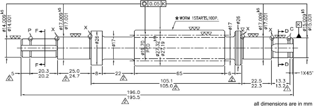
Figure 1. Worm drafting.
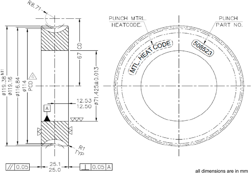
Figure 2. Worm wheel drafting.
2.1 20MnCr5 material specimen (worm) test
The physical behaviours of the material need to be assessed by experimental testing, even though all material properties are readily available. This is expected to help further work and identify the material behaviours. In the worm and worm wheel assembly operation, the worm may experience more damage because of continuous wear, so there is a need to focus more on the worm material. The existing model of the worm is fabricated from 20MnCr5 material. The soot blower manufacturer directly purchases 20MnCr5 material with the necessary surface hardness (30 HRC) from suppliers to manufacture the worm. Furthermore, the material hardness is increased by oil quenching to up to 60 HRC; this is required to increase the surface wear strength. Understanding the existing worm material behaviours under tension is essential for further investigation, correlation establishment, and validation purposes. Tensile testing of the existing worm made of 20MnCr5 is conducted on a universal testing machine (UTM), and the tensile testing specimen drawing is as shown in Figure 3. The 20MnCr5 material specimens of 30 HRC and 60 HRC surface hardness values were received from the manufacturer. The actual 20MnCr5 material specimens used in the tensile tests are shown in Figure 4. Testing was carried out on the material specimens with both 30 HRC and 60 HRC surface hardness values, and Table 1 indicates the results of these specimens.
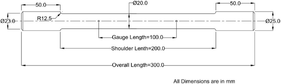
Figure 3. Tensile test specimen.
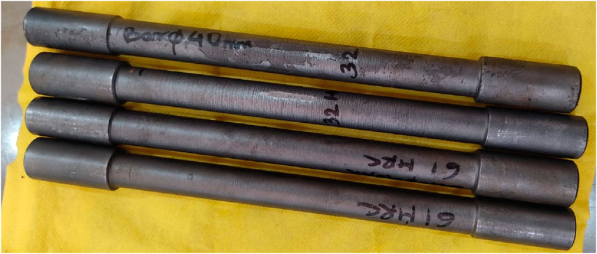
Figure 4. Tensile test specimen made of 20MnCr5 material.
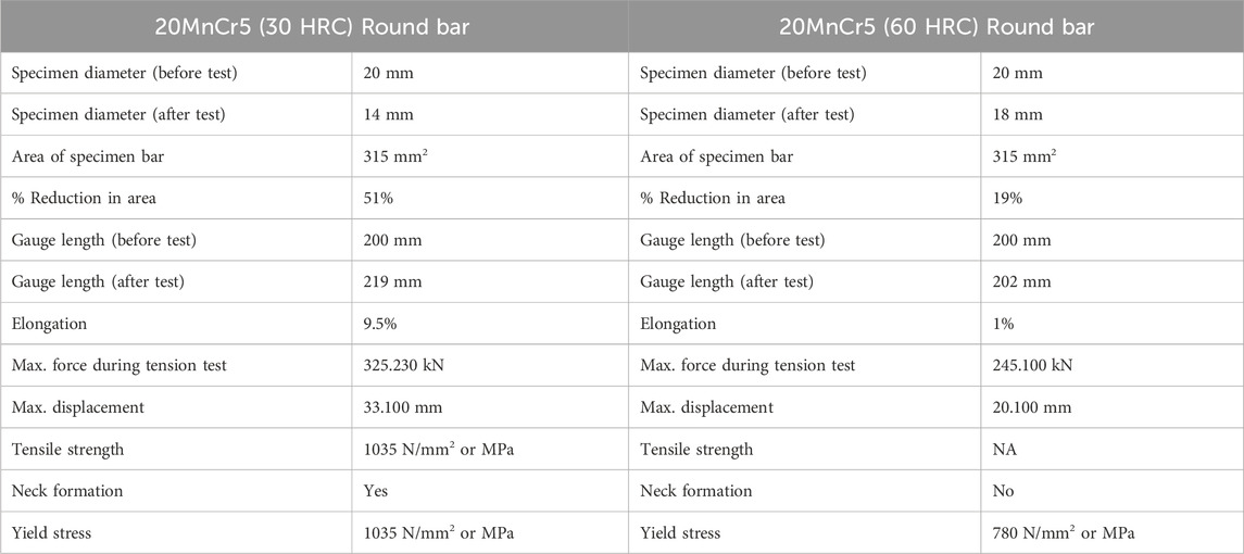
Table 1. Tensile test results.
Figure 5 describes the behaviour of the 20MnCr5 material with 30 HRC surface hardness after tensile testing on the UTM. The graph indicates the corresponding stress and strain values, with neck formation after applying the tensile load. Neck formation indicates that the material behaviour is ductile; this is mainly because of the lower surface hardness of the material.
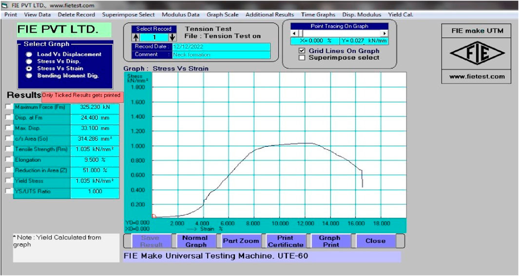
Figure 5. Stress–strain diagram of the 20MnCr5 material with a surface hardness of 30 HRC.
Figure 6 indicates the stress–strain diagram of the 20MnCr5 material with 60 HRC surface hardness. This curve was obtained after tensile testing on the UTM. No neck formation was observed during the test, so the material behaviour is brittle rather than ductile, and failure occurs mainly by wear. This is mainly attributed to the greater surface hardness of the material.
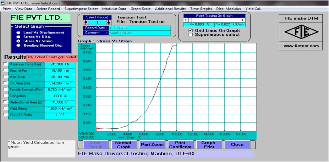
Figure 6. Stress–strain diagram of the 20MnCr5 material with a surface hardness of 60 HRC.
2.2 Modelling of worm and worm wheel
A suitable modelling software was utilised for computer-aided design (CAD) modelling of the worm-gear set. Mechanical designers use this simple application for sketching ideas, experimenting with different features and specified dimensions, and creating models with detailed part drawings. The CAD program begins with a two-dimensional model and progresses to a three-dimensional solid model of the worm-gear set based on the manufacturer’s drawings. These models comprise both the worm and worm wheel. The total proportions of the worm-gear set are based on the supplier’s depiction; a single worm and a worm wheel were manufactured and combined to make an assembly. The CAD model of the worm-gear set was built using the drawings and measurements given. Figure 7 shows the assembly of the worm-gear set.
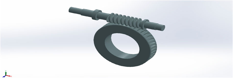
Figure 7. Worm-gear set in its assembled position.
2.3 FEA of the worm-gear set
Inspecting the stability of the worm gear material is critical for ensuring its safety. Many engineering problems are often solved using differential or integral equations, and engineers must obtain quick solutions to these designs given the rapid product design cycles. Hence, approximate solutions are obtained often with decent amounts of time and effort. FEA is an example of an approximate solution and is required to ensure material stability. Step 1: FEA of the worm-gear set is useful for analysing the corresponding structures using a computer, which may help minimise the time required and reduce the prototyping cost. Furthermore, CAD might provide better solutions. Step 2: The CAD model of the worm-gear set is assembled using the previously specified modelling tool and imported into an appropriate FEA application. Step 3: Generating the mesh and meshing connections divides the model geometry into several sections based on the connected nodes. The tetrahedral-type meshing was used to prepare the model in this study, as indicated in Figure 8. The tetrahedral solid structural element SOLID 187 with ten 3D nodes along all attributes was used for meshing. The SOLID 187 element has a quadratic displacement characteristic and is perfect for replicating non-regular mesh types (which are created with different CAD/CAM systems). This element entails three degrees of freedom with 10 nodes in the nodal x, y, and z directions. Figure 9 depicts the worm gear assembly model in the meshing condition.

Figure 8. Structural element (Stolarski et al., 2018).
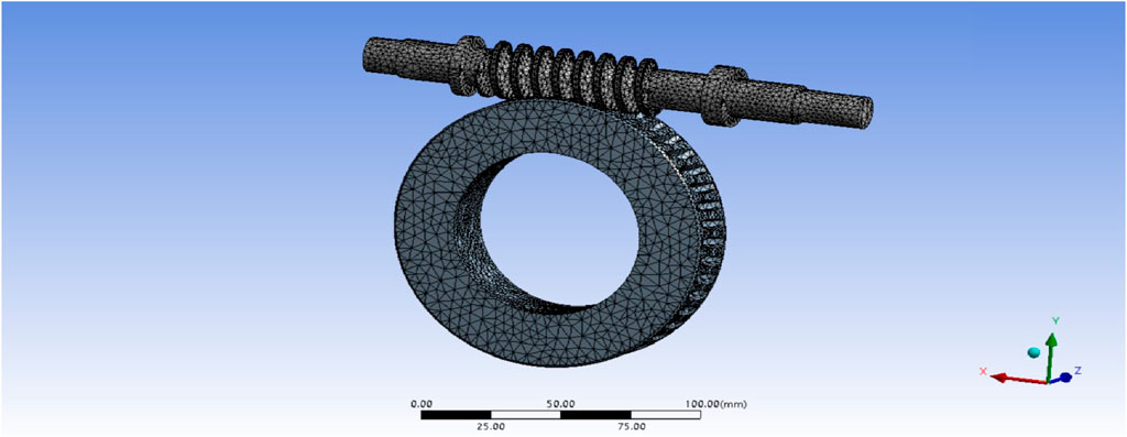
Figure 9. Worm-gear assembly model in the meshing condition.
2.3.1 Convergence and connection (contact) details
A convergence study was performed for the meshing, with successive mesh refinements from elements of size 3–2.4 mm, and the changes in the observed von Mises stress were less than 2%. Meshing was done with a fine relevance centre of the element to match the assembly profile. Static stress analysis of the worm-gear set was performed on the basis of the linear isotropic material properties from the actual practical tensile test results by referring to the material properties from available industrial catalogues. These properties mainly include the yield stress of the material, Poisson’s ratio, and tangential modulus (i.e., 0.2% of the Young’s modulus). The material properties are summarised in Table 2.
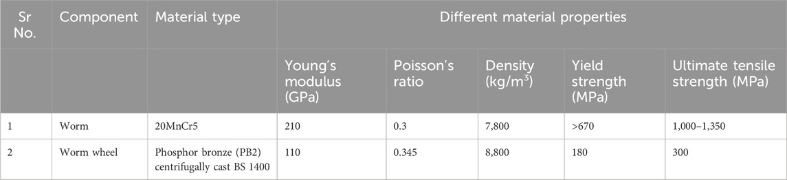
Table 2. Standard material properties (Product Catalogue, 2016; Product Catalogue, 2023; Industrial Product, 2019).
Element size used = 2.40 mm.
Number of elements = 69,902.
Number of nodes = 181,356.
The contact/connection elements may be considered as a skin covering the surfaces that are expected to interact with each other. One side of this contact pair is referred to as the contact, and its mate is called the target. There are five types of contact in FEA (as noted below), of which two are used in the linear analysis and remaining three are used in the non-linear analysis. Any contact behaviour can be characterised by two features, namely, the separation and sliding characteristics.
a. Bonded contact (linear type)
b. No-separation contact (linear type)
c. Frictionless contact (non-linear type)
d. Frictional contact (non-linear type)
e. Rough contact (non-linear type)
The present analysis uses frictional contact, which is of the non-linear type. In frictional contact, there is possible separation between the contact and target bodies, and sliding action is also possible with this contact. In this type of contact, it is assumed that the mating surfaces are rough and that frictional coefficient μ > 0. The frictional coefficient (μ) has to be supplied manually (Stolarski et al., 2018). Thus, frictional contact is utilised to create a link for the worm-gear set. The thread region of the worm comes into contact with the teeth of the worm wheel. To achieve contact, the two teeth faces are chosen as indicated in Figure 10.
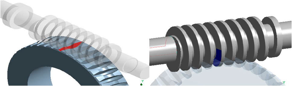
Figure 10. Worm gear in contact.
The friction coefficient in a worm-type gear drive is proportional to the speed of rubbing, and the relative velocity of the worm-gear set determines the rubbing speed. Figure 11 depicts the velocity triangle, and the coefficient of friction is chosen using the following formula (Bhandari, 2010):
i.e.,
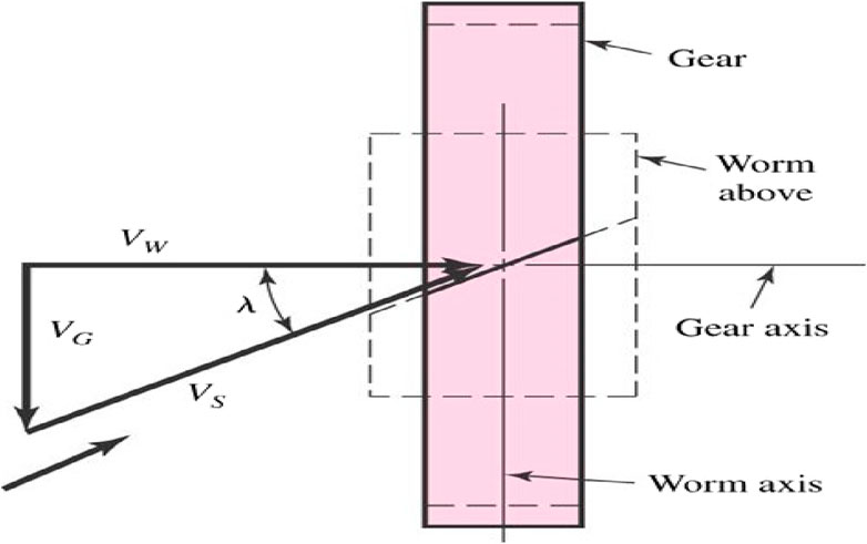
Figure 11. Velocity of sliding (Bhandari, 2010) for a rubbing velocity of 0.355 m/s and frictional coefficient (μ) of 0.057 (Bhandari, 2010).
Step 4: The mechanical properties of the material of the worm-gear set are shown in Table 2. These characteristics and tensile test data are employed in the FEA.
Step 5: Before analysing any structure, the boundary conditions must be specified. Here, the input power is delivered from the worm to the worm wheel.
2.3.2 Constraints
In the stressed region, the mesh is refined locally by mesh grading. As per the assembly constraints, the degree of freedom for the worm is around the X direction, which is free and fully open for rotation. Lateral movement of the worm is restricted between two supporting bearings in the assembly. For the worm wheel, the degree of freedom is around the Z axis and is fully free for rotation. The remaining degrees of freedom in the X and Y directions are restricted. The initial torque applied to the worm did not produce satisfactory stress values, so the radial, tangential, and axial loads were calculated and applied to the worm as per the boundary conditions.
2.3.3 Loading
According to data from the soot blower manufacturer, the input power is 0.75 HP, i.e., 0.75 × 0.746 = 0.56 kW. The wheel turns at 7.6 rpm according to the specifications, and the speed ratio is 45. Thus, the worm is considered to rotate at 7.6 × 45 = 342 rpm.
Initially, the input moment is 15,640 N∙mm about the axis of the worm and is applied at the end. However, it was observed that the results and stress values achieved were not satisfactory; therefore, the calculated radial, tangential, and axial loads were applied to the worm as per the given boundary conditions. The resultant load is ultimately applied at the end of the worm, as shown in red colour in Figure 12.
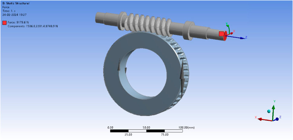
Figure 12. Boundary conditions and loading.
Step 6: In the worm-gear set, both ends of the worm are cylindrical in shape (as shown in yellow colour in Figure 13) along the tapered roller bearing of width 13.254 mm. Hence, the displacement support is applied to this area to ensure that the customised degrees of freedom remain. The worm-gear set is then analysed as per the critical aspects to evaluate the reaction.
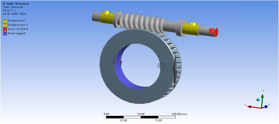
Figure 13. Bearing displacement area with end loading.
2.3.4 Analysis of static-type stress (equivalent von Mises stress)
a) Solution
Static stress analysis of the worm-gear set is performed on the basis of the linear isotropic material properties from actual practical tensile test results by referring to the material properties available in the industrial catalogues. These properties mainly include the yield stress of the material, Poisson’s ratio, and tangential modulus (i.e., 0.2% of the Young’s modulus). The static stress analysis shows the stability of the worm-gear set under the given inputs. The worm-gear arrangement is obtained using the FE solver feature for the given inputs described above.
b) Stress results (postprocessing)
Postprocessing entails examining the numerous outcomes, such as deformations and stresses. Figure 14 depicts the deformations of the worm and worm wheel in contact. The total lateral deformation of the gear assembly is about 0.014 mm; this deformation is compensated by the bearings attached to the worm extension, which restrict its movements. The deflections of the worm and worm wheel cannot be identified separately.
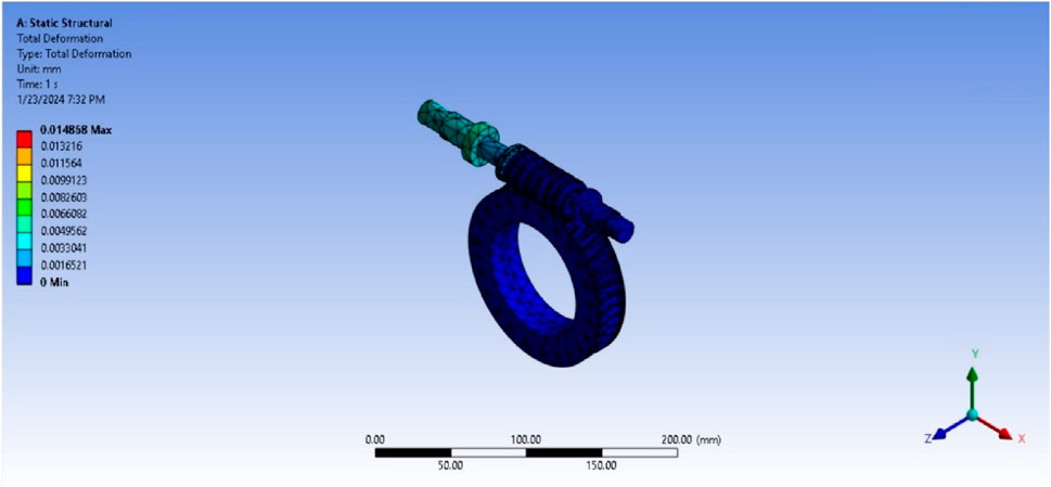
Figure 14. Worm and worm wheel deformation.
The maximum stress observed in the x direction is 257.12 MPa, which is equivalent to the bending stress. The assembly and torque boundary conditions are applied in the X direction, and the multidirectional forces on each tooth are generated. These forces are either fully or partially in contact with each other, so they are considered to be the same as the bending stress. The bending stress is calculated in the direction of application of the force or torque. Figure 15 describes the equivalent bending stress.
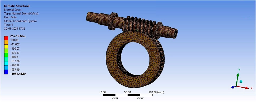
Figure 15. Normal stress (equivalent bending stress).
The maximum equivalent stress (von Mises stress) in the worm is 907.49 MPa, which is within the limit of the yield stress of the 20MnCr5 material, i.e., 1,350 MPa, and closer to the experimental values of 780 MPa and 1,035 MPa. Figure 16 describes the von Mises stress in the worm. The maximum equivalent stress in the worm wheel is 143.81 MPa, which is within the limit of the yield stress of the PB2 material, i.e., 300 MPa. Figure 17 indicates the maximum equivalent stress in the worm wheel.
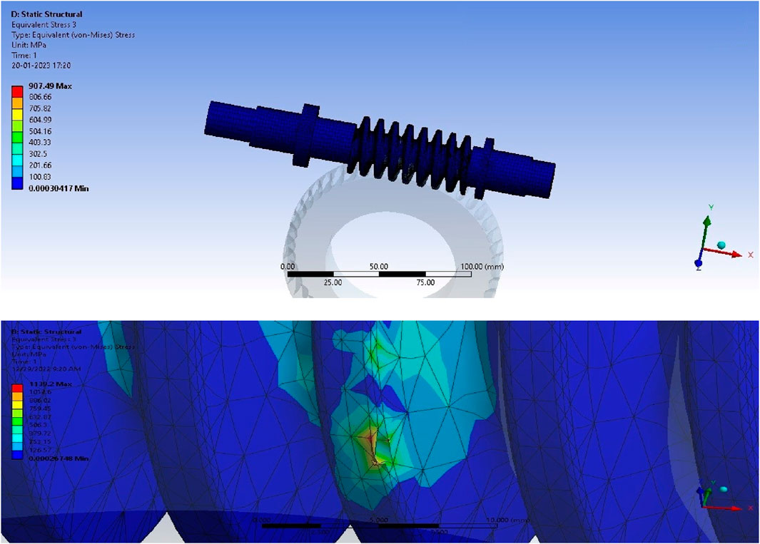
Figure 16. Von Mises stress in the worm.
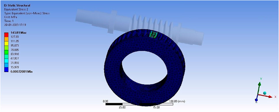
Figure 17. Equivalent von Mises stress in the worm wheel.
The FEA results for the deformations, normal (bending) stresses, and equivalent stresses in the worm and worm wheel are in close agreement with the analytical calculated values. Furthermore, the FEA values of the equivalent stresses are below the yield limits of the materials of the worm and worm wheel as well as the experimentally obtained values of the worm material. Thus, it can be observed that the FEA results are appropriate for validation (Product Catalogue, 2016; Product Catalogue, 2023; Design Manual for Cylindrical Worm Gearing, 2014; Honkalas et al., 2023).
2.4 Analytical method for analysing gear forces, worm bending stress, and deformation
Figure 18 shows reactions at worm bearing (Design Manual for Cylindrical Worm Gearing, 2014).
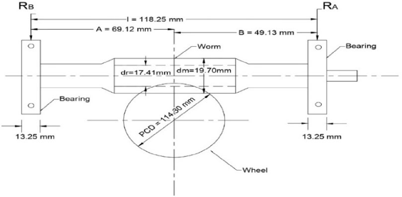
Figure 18. Worm bearing reactions.
a) Tangential force of the worm gear: The tangential force produced can be computed as
b) Worm separating force: This force is given as
c) Worm-gear thrust force: The axial thrust force is given as
d) Gearing reactions of the worm: The reaction forces occurring at the worm are given as
e) Worm bending stress: The bending stress generated in the worm is computed as
or
f) Worm deflection: The deflection of the worm is given as
The computed value of the bending stress is therefore
The deflection/deformation of the worm is (Design Manual for Cylindrical Worm Gearing, 2014) given by
2.4.1 Bending stress (allowable)
The worm bending stress calculated using the aforementioned method must be less than 17% of the ultimate tensile strength of the worm core material for normal running torque and 75% of the worm yield strength of the core material for maximum momentary torque overload suitable for the gear set. These permissible stress values are conservative estimates and represent the worm-thread area’s usual stress at concentration and stresses at torsion. The bending stress is equal to 17% of the maximum tensile strength = 17/100 × 1,350 = 229.51 MPa; furthermore, the yield strength is 75% of the maximum tensile strength = 75/100 × 670 = 502.5 MPa. Thus, the computed bending stress value of 214.401 MPa is less than both 229.51 MPa and 502.50 MPa (Design Manual for Cylindrical Worm Gearing, 2014).
2.4.2 Worm deflection (allowable)
For typical operating loads, the maximum permitted worm-shaft deflection should be less than
Accordingly, the calculated worm deflection of 0.07 mm is less than 0.0705 mm.
2.5 Comparison of worm and worm wheel data obtained from theoretical values from standard material properties, analytical calculations, and FEA results
Table 3 presents the comparison of the obtained worm and worm wheel results from different methods. The worm material is 20Mncr5, and the wheel material is centrifugally cast PB2.
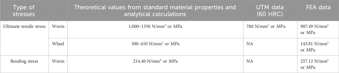
Table 3. Comparison of worm and worm wheel analysis results.
2.6 Analytical design of experiments (DOE) to improve worm-gear set efficiency
The efficiency of the soot blower’s worm-gear set was determined analytically based on the ISO and AGMA standards. The worm and worm wheel currently have an estimated efficiency of 68.8%. Hence, the analytical DOE method was used to determine the most important aspects influencing efficiency. DOE is a branch of statistics that entails determining the variables impacting the value of a parameter or combination of parameters according to planning, execution, analysis, and interpretation of controlled tests; it is a flexible tool for data collection and analysis that encompasses a variety of experimental scenarios, allowing the manipulation of a large number of input factors to see how they affect the intended results. By varying many inputs at the same time, DOE can help uncover critical interactions that may otherwise go undetected when testing components individually. All possible combinations (full factorial) or only a subset (fractional factorial) can be investigated. A well-planned and executed experiment can provide a lot of information on the effects of individual or multiple factors on a response variable. Different experiments would involve keeping certain variables constant while changing the others. Compared to adjusting the factor levels concurrently, the “one factor at a time” (OFAT) approach to knowledge processing is not sufficient. The statistical techniques of planned experiments that are in use today are based on R. A. Fisher’s work from the 20th century; Fisher emphasised the need to take time to properly evaluate the design and execution of experiments beforehand to avoid common analytical difficulties. Blocking, randomisation of values, and replication of values are some of the key ideas for constructing an experiment. DOE may also be used to confirm the hypothesised input/output relationships and provide prediction equations appropriate for what-if analyses (Antony, 2014). DOE is thus vital for improving the performance (efficiency) of the worm-gear set. The following are different processes for developing tests to find the most important characteristics influencing the efficiency of the worm-gear set. The efficiency calculations are utilised in DOE, and these findings may help increase the efficiency of the worm-gear set design by introducing more parametric variations (Bhandari, 2010; Design Manual for Cylindrical Worm Gearing, 2014).
2.6.1 Efficiency of the worm-gear drive (η)
By substituting the value of the number of teeth in the worm as
The above expression indicates that the worm lead (
From Eq. (27), it can be concluded that the rubbing velocity (Vs) is the governing factor of efficiency dependent upon the gear module (m) and pitch circle diameter (PCD) of the worm (
The value of
Now, substituting the equation for the PCD of the worm wheel (and fixing the centre distance (CD) as per requirement)
The efficiency equations were simplified thoroughly, and it was observed that the gear module, m, was one of the most significant factors affecting worm-gear efficiency. Finally, it was determined that the number of worm wheel teeth (
Estimating the standard range of values of m from the existing base value of 2.54 mm requires some suitable variations. To perform Excel-based DOE, appropriate module ranges were selected and the calculations were obtained. The number of worm wheel teeth (Z2) required to achieve maximum worm-gear efficiency was calculated for the given constraints as per manufacturing feasibility. An Excel sheet was prepared to assess the overall dimensions of the worm-gear set. The trial-and-error values of the gear module were thus determined to vary in the range of +4.25%, and the spreadsheet calculations and graphs were prepared. The output requirement for worm rotation is 7.6 rpm with +5% or –5% variations. The number of worm wheel teeth (Z2) is restricted to variations of 43, 44, 45, 46, and 47 teeth.
2.6.2 DOE for improving efficiency based on Z2 and m
An Excel spreadsheet was used for the calculations. Table 4 shows the changes in efficiency with changes in the gear module and number of worm wheel teeth. Based on the profile correction factor, this sheet shows the corresponding output rpm (n2) and root diameter (dr). The blue coloured values indicate the suggested values of the gear module and number of teeth along with the corresponding increase in efficiency (74.6%) as per the design and manufacturing feasibility constraints. The red coloured values indicate the existing values of the gear module and number of teeth for the corresponding efficiency of 68.8%. Figure 19 illustrates the efficiency values at the corresponding gear module and number of worm wheel teeth. The minimum required value of the root diameter is derived using the dedendum of the worm and worm gear (b) = (1.157 × axial pitch)/3.14 = 2.93 mm. Thus, the root diameter (dr) = d–2b = 13.84 mm.
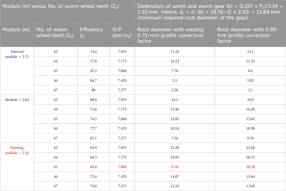
Table 4. DOE based on the number of worm wheel teeth (Z2) and gear module (m).
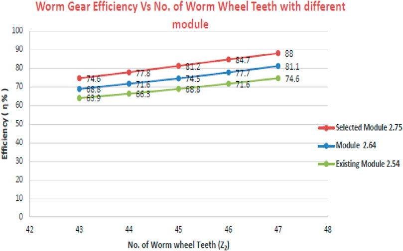
Figure 19. Worm-gear efficiency versus number of worm wheel teeth for different modules.
2.6.3 Suggested parametric changes for improving worm-gear efficiency
An Excel spreadsheet was prepared to test the worm-gear dimensions on different modules, as noted previously. The following are the different parametric changes to the worm-gear dimensions for the given manufacturing constraints to improve the existing efficiency.
Manufacturing constraints:
Centre distance (CD) = 67 mm, root circle diameter (dr) = d–2b = 19.70–(2 × 2.93) = 13.84 mm.
where d = PCD of Worm, b = dedendum of worm and worm gear.
Thus, the root diameter should not be less than 13.84 mm, and the CD should be 67 mm.
Suggested module = 2.75 mm and profile correction factor = 0.90.
The proportionate dimensions of the worm gear are calculated and tabulated in Table 5.
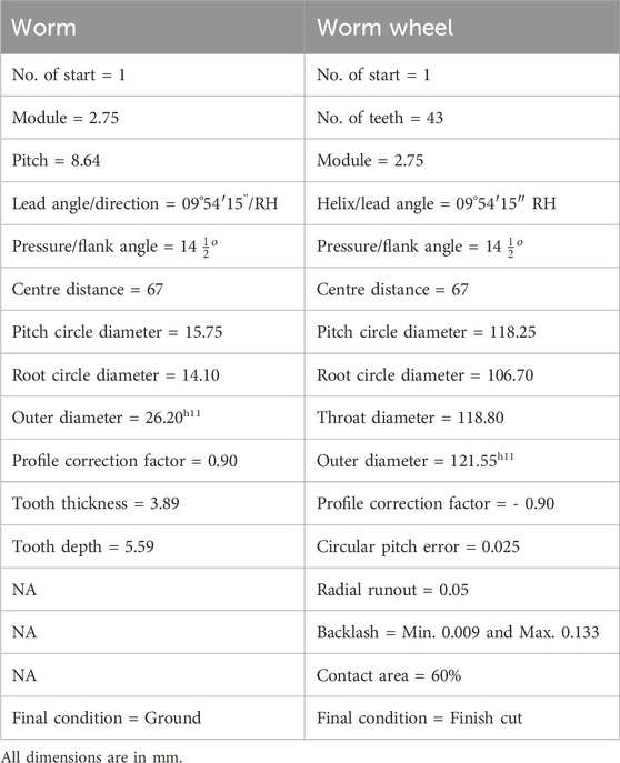
Table 5. Worm-gear set suggested dimensions.
3 Results and discussion
• UTM test of 20MnCr5 worm material with 30 HRC and 60 HRC surface hardness values provides the tensile and yield strengths. This test shows that a material with greater hardness fails rapidly, affecting the efficiency and life of the worm.
• The equivalent von Mises stress obtained for the worm is less than its ultimate strength, i.e., 907 MPa, which is less than the range of 1,000–1,350 MPa (for the 20MnCr5 worm material) and closer to the experimental yield stresses, i.e., 780 MPa and 1,035 MPa.
• The equivalent von Mises stress obtained for the worm wheel is less than its ultimate limit, i.e., 143.81 MPa, which is less than the accepted range of 300–410 MPa (for the centrifugally cast PB2 worm wheel material).
• The total deformation of the worm and worm wheel assembly is 0.014 mm, which is in close agreement with the analytically calculated value of deformation (0.07 mm).
• The maximum stress observed in the x direction is 257.12 MPa, which is equivalent to the bending stress and in close agreement with the theoretically calculated bending stress.
• The worm and worm wheel analysis data are obtained from theoretical values using standard material properties, analytical calculations, experimental test results, and FEA results, all of which shows that they are in close agreement.
• The analytical DOE approach is successfully utilised to determine the number of worm wheel teeth (
• During the design calculations and DOE, it was found that there was a correlation between the coefficient of friction (μ) of the material and gear module (m). Accordingly, the corresponding value of the rubbing speed (Vs) is 0.355 m/s for a coefficient of friction (μ) of 0.057.
• The performance (efficiency) of the worm and worm wheel is improved from 68.8% to 74.6%, which is an increment of 8.5%; this results in lower power consumption during industrial application.
• Profile modifications are thus suggested for manufacturing a modified worm-gear set with improved efficiency than that available with the extant worm and worm wheel.
4 Conclusion
The goal of this study was to investigate a specific methodology for finding the most significant factors affecting the performance (efficiency) of the worm-gear set and ultimately the performance improvements required for the worm-gear set used in a soot blower through the profile modification approach. The number of worm wheel teeth (
Data availability statement
The original contributions presented in the study are included in the article/Supplementary Material; further inquiries can be directed to the corresponding author.
Author contributions
SS: formal analysis, funding acquisition, investigation, methodology, project administration, and writing–review and editing. RH: investigation, methodology, project administration, resources, validation, visualization, writing–original draft, and writing–review and editing. BD: investigation, methodology, project administration, resources, supervision, validation, and writing–review and editing. PP: conceptualization, formal analysis, methodology, resources, and Writing–review and editing. RC: funding acquisition, investigation, methodology, project administration, validation, and writing–review and editing. EN: investigation, methodology, validation, visualization, and writing–original draft.
Funding
The author(s) declare financial support was received for the research, authorship, and/or publication of this article.
The authors extend their appreciation to King Saud University for funding this work through Researchers Supporting Project number (RSP2023R164), King Saud University, Riyadh, Saudi Arabia. This article was co-funded by the European Union under the REFRESH – Research Excellence For Region Sustainability and High-tech Industries project number CZ.10.03.01/00/22_003/0000048 via the Operational Programme Just Transition and has been done in connection with project Students Grant Competition SP2024/087 “Specific Research of Sustainable Manufacturing Technologies” financed by the Ministry of Education, Youth and Sports and Faculty of Mechanical Engineering VŠB-TUO.
Acknowledgments
The authors wish to thank the Walchand Institute of Technology and Laxmi Hydraulics Pvt. Ltd., Solapur, for their contributions to this work.
Conflict of interest
The authors declare that the research was conducted in the absence of any commercial or financial relationships that could be construed as a potential conflict of interest.
Publisher’s note
All claims expressed in this article are solely those of the authors and do not necessarily represent those of their affiliated organizations, or those of the publisher, the editors, and the reviewers. Any product that may be evaluated in this article, or claim that may be made by its manufacturer, is not guaranteed or endorsed by the publisher.
Abbreviations
Z1, number of worm starts; Z2, number of worm wheel teeth; q, diameter quotient; m, gear module (mm); a, CD, centre distance (mm); γ, λn, lead angle/helix angle; α, Øn, pressure angle/flank angle; N, n1, input rpm of the worm wheel; n2, output rpm of the worm wheel; d1, pitch circle diameter (PCD) of the worm wheel (mm); Vs, rubbing velocity (m/s); μ, coefficient of friction; Waw, thrust force of the worm in axial direction (N); Wtg, force of the worm wheel in tangential direction (N); TG, output worm gear torque (Nm); Dm, mean diameter (worm gear, PCD in mm); Wsg, separating force of worm gear (N); Wsw, separating force of the worm (N); Wag, thrust force of worm gear in the axial direction (N); Wtw, tangential force of the worm (N); R, reaction force (N); Sb, bending stress of the worm (Mpa); M, bending moment (Nm); dr, root diameter of the worm (mm); F, total reaction force (N); K, location factor of the equivalent load; y, worm deflection (mm); l, bearing span of the worm (mm); E, modulus of elasticity (N/mm2); DOE, design of experiments; UTM, universal testing machine.
References
Adesola, O. K., Abu, R., Oriolowo, K. T., Adetan, D. A., and Bamiro, O. A. (2018). Development of computer based model for design and analyses of worm gearing mechanism. EJERS, Eur. J. Eng. Res. Sci. 3 (12), 84–90. doi:10.24018/ejeng.2018.3.12.1040
Aleksandar, S., Krsmanovic, D., Radosavljevic, S., Ivanovic, L., and Stojanovic, B. (2017), 3. Fascicule, 2067–3809. ISSN. Power losses of worm gear pairs Bull. Eng. Tome X.
Antony, J. (2014). Design of experiments for engineers and scientists. Philadelphia, PA, USA Jiju Antony. Elsevier.
Basu, S., and Kumar Debnath, A. (2015). Boiler control system in power plant instrumentation and control handbook. Amsterdam: Elsevier, Academic Press.
Bhandari, V. B. (2010). Design of machine elements. New York, NY, USA Tata McGraw-Hill Education, 725–727.
Croccolo, D., De Agostinis, M., Olmi, G., and Vincenzi, N. (2020). A practical approach to gear design and lubrication: a review. Lubricants 8, 84. doi:10.3390/lubricants8090084
Deng, X., Zhu, W., Chen, Y., Chen, S., and Wang, J. (2017). Optimal design for an end face engagement worm gear with multiple worm-wheel meshing. Chin. J. Mech. Eng. 30 (1), 144–151. doi:10.3901/cjme.2016.1025.126
Design Manual for Cylindrical Worm Gearing, (2014). AGMA 6022-C93 (revision and redesignation of AGMA 341.02). Alexandria: American Gear Manufacturers Association.
Honkalas, R., Deshmukh, B., and Pawar, P. (2021). A review on design and efficiency improvement of worm and worm wheel of a gear motor. J. Phys. Conf. Ser. 1969, 012023. doi:10.1088/1742-6596/1969/1/012023
Honkalas, R., Deshmukh, B., and Pawar, P. (2023). Investigation and analysis of existing design of worm and worm wheel of a gear motor used in a soot blower. Mater. Today Proc. 72, 904–910. Part 3. doi:10.1016/j.matpr.2022.09.089
Kawalec, A., Wiktor, J., and Ceglarek, D. (2006). Comparative analysis of tooth-root strength using ISO and AGMA standards in spur and helical gears with FEM-based verification J. Mech. Des. 128 1141. Transaction of ASME. doi:10.1115/1.2214735
Kim, G.-H., Lee, J.-W., and Seo, T.-Il (2013). Durability characteristics analysis of plastic worm wheel with glass fiber reinforced polyamide. Materials 6, 1873–1890. doi:10.3390/ma6051873
Mautner, E.-M., Werner, S., Stemplinger, J.-P., and Stahl, K. (2016). Investigations on the efficiency of worm gear drives. Michigan, MG, USA: The AGMA Fall Technical Meeting in Detroit, 15FTM20.
Pany, C. (2021). Cylindrical shell pressure vessel profile variation footprint in strain comparison of test data with numerical analysis. Liq. Gaseous Energy Resour. 1 (2), 91–101. doi:10.21595/lger.2021.22163
Pany, C. (2021). Estimation of correct long-seam mismatch using FEA to compare the measured strain in a non-destructive testing of a pressurant tank: a reverse problem. Int. J. Smart Veh. Smart Transp. 4 (1), 16–28. doi:10.4018/ijsvst.2021010102
Patil, S. S., Karuppanan, S., Atanasovska, I., and Abdul Wahab, A. (2014). Contact stress analysis of helical gear pairs, including frictional coefficients. Int. J. Mech. Sci. 85, 205–211. doi:10.1016/j.ijmecsci.2014.05.013
Sankar, S., and Nataraj, M. (2011). Profile modification—a design approach for increasing the tooth strength in spur gear. Int. J. Adv. Manuf. Technol. 55, 1–10. doi:10.1007/s00170-010-3034-3
Siebert, H. (2011). Worm gears- higher energy efficiency and less strain on Resources. Rancho Cucamonga, CA, USA Gear Technology.
Sreelakshmi, M. G., and Pany, C. (2016). Stress analysis of metallic pressure vessels with circumferential mismatch using finite element method. Int. J. Sci. Eng. Res. 7 (Issue 4).
Stolarski, T., Nakasone, Y., and Yoshimoto, S. (2018). Engineering analysis with ANSYS software. Elsevier Sci.
Tosic, M., Larsson, R., Stahl, K., and Lohner, T. (2023). Thermal elastohydrodynamic analysis of a worm gear. Machines 11, 89. doi:10.3390/machines11010089
Wang, X., and Morrish, L. (2003). Worm gear meshing stiffness calculations based on experiments. Trans. Eng. Sci. 44. WIT Press, 1743–3533. www.witpress.com ISSN.
Keywords: worm gears, soot blower, analysis, efficiency, analytical design of experiments, profile modification
Citation: Honkalas R, Deshmukh B, Pawar P, Salunkhe S, Cep R and Abouel Nasr E (2024) Performance improvement of set of worm gears used in soot blower through profile modification. Front. Mech. Eng 10:1360502. doi: 10.3389/fmech.2024.1360502
Received: 23 December 2023; Accepted: 06 March 2024;
Published: 17 May 2024.
Edited by:
Kaushik Kumar, Birla Institute of Technology, Mesra, IndiaReviewed by:
Chitaranjan Pany, Vikram Sarabhai Space Centre, IndiaPing Liu, State Grid Jiangsu Electric Power Co., Ltd., China
Copyright © 2024 Honkalas, Deshmukh, Pawar, Salunkhe, Cep and Abouel Nasr. This is an open-access article distributed under the terms of the Creative Commons Attribution License (CC BY). The use, distribution or reproduction in other forums is permitted, provided the original author(s) and the copyright owner(s) are credited and that the original publication in this journal is cited, in accordance with accepted academic practice. No use, distribution or reproduction is permitted which does not comply with these terms.
*Correspondence: Rahul Honkalas, rahul.honkalas@gmail.com; Sachin Salunkhe, sachinsalunkhe@gazi.edu.tr