Effect of Surface Roughness on Adhesive Instabilities for the Elastic Layer
 Junki Joe
 M. D. Thouless1,2
  J. R. Barber
- 1Department of Mechanical Engineering, University of Michigan, Ann Arbor, MI, United States
- 2Department of Materials Science and Engineering, University of Michigan, Ann Arbor, MI, United States
If an incompressible elastic layer bonded to a rigid plane is placed close to a second rigid plane, adhesive interactions between the surfaces can cause elastic instabilities. These lead to spatially non-uniform traction and gap distributions which exhibit a regular pattern with a characteristic wavenumber. However, real surfaces are never completely plane. In this paper, we consider the influence of surface roughness on the instability, with particular reference to the force-displacement relation. With random roughness profiles, the traction distributions are always spatially irregular, so the onset of instability is more difficult to define. One approach is to monitor the amplitude of the power spectrum of the distribution near the characteristic wavenumber. Since surface roughness generally reduces the mean adhesive traction, we might expect it to exert a stabilizing effect. Numerical results confirm this for moderate to large RMS amplitudes, but show that low RMS roughness can actually trigger the instability in ranges where the uniform layer would be stable. The resulting traction-displacement relation is then found to be approximately linear with a slope close to that at the point where the uniform solution loses stability.
Introduction
If two bodies with plane surfaces are placed close together, they may experience attractive [e.g., van der Waals'] forces, or forces involving both attractive and repulsive ranges (Jones, 1924; Maugis, 2013). Since the attractive forces must eventually decay with increasing separation, they have the character of a “negative spring,” which can trigger an elastic instability. If the bodies are incompressible [Poisson's ratio ν = 0.5], or if a body comprising a thin elastic layer bonded to a rigid plane surface is attracted to another rigid plane surface, the instability may result in a non-uniform [typically periodic] pattern of alternating regions of contact and separation. Patterns of this kind have been observed experimentally (Mönch and Herminghaus, 2001; Gonuguntla et al., 2006a), and predicted theoretically, based on energetic arguments (Shenoy and Sharma, 2001; Sarkar et al., 2004). In particular, the characteristic length scale of the pattern correlates with the unstable wavelength in a linear perturbation of the uniform state. The patterning instability also modifies the mean traction-separation characteristic for the layered system, generally leading to different behavior during approach and separation and consequent hysteresis losses (Ciavarella et al., 2019).
The instability permits self-assembly processes such as elastic contact lithography [ECL], where the pattern in a polymer film is fixed by UV curing or by lowering the temperature (Sarkar and Sharma, 2010; Ghosh et al., 2016, 2017). In ECL, the periodicity and size of the pattern are critical parameters and various methods have been proposed to control them, including the use of a curved substrate (Ghosh et al., 2018), an imprinted stamp (Gonuguntla et al., 2006b; Mukherjee et al., 2007; Bhandaru et al., 2017), or a pre-strained substrate (Davis-Purcell et al., 2018). Also, electric fields can be used to extend the range of attraction relative to van der Waals' forces and to provide greater control of the process, whilst retaining a similar morphology (Arun et al., 2006; Sarkar et al., 2008; Sahoo et al., 2019).
Real surfaces are of course never perfectly smooth, and surface roughness generally reduces both the maximum pull-off traction, and the maximum negative slope of the effective traction-separation law (Joe et al., 2018). This should reduce the tendency for patterning in the contact of layered bodies. However, sufficiently small amplitude roughness might also serve as an initial perturbation to trigger an instability. In this paper, we shall therefore use a numerical solution to examine the effect of roughness on both the generation of patterns and the mean traction-separation relation. In particular, we shall examine the extent to which the effect of roughness can be captured by using a modified adhesive traction law developed for the contact of rough elastic half spaces.
Deformation of a Thin Layer
We consider an elastic layer of thickness h bonded to a rigid plane, and define Cartesian coordinates (x, y) in the plane of the layer surface and corresponding dimensionless coordinates ξ = x/h, η = y/h. If a second rigid plane is placed a distance ḡ away from the undeformed surface of the layer as shown in Figure 1, the local gap between the surfaces will then be
where u(ξ, η) is the local outward normal elastic displacement of the layer surface.
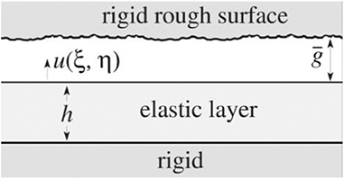
Figure 1. A rigid body with a plane surface that may contain some surface roughness is placed near to an elastic layer bonded to a rigid foundation. The mean gap is ḡ and u(ξ, η) is the local elastic displacement of the layer surface.
Interface Energy
We assume that the adhesive tractions between the surfaces can be described by a traction law σ(g), where g is the local value of the gap. We can then also define the mean interface energy per unit area as
and a stable final configuration will be one that minimizes the total potential energy Π = U + Γ, where U is the mean elastic strain energy per unit area.
Elastic Strain Energy
The normal traction σ(ξ, η) at the free surface of the layer needed to produce a sinusoidal normal elastic displacement u(ξ, η) = uζcos(ζξ) is
where
(Hannah, 1951), and we recall that ξ = x/h, so ζ is a dimensionless wavenumber.
In this paper, we shall restrict attention to incompressible layers [ν = 0.5], for which the corresponding dimensionless compliance 1/f(ζ) is shown as a function of dimensionless wavenumber ζ in Figure 2. The curve exhibits a maximum of ~0.482 at a wavenumber ζ ≈ 2.1, and zero compliance for uniform loading [f(ζ) → ∞ as ζ → 0]. One consequence of this is that with general loading σ(ξ, η), the mean value of u is zero and hence ḡ is determined by the rigid-body approach which is a controlled parameter.
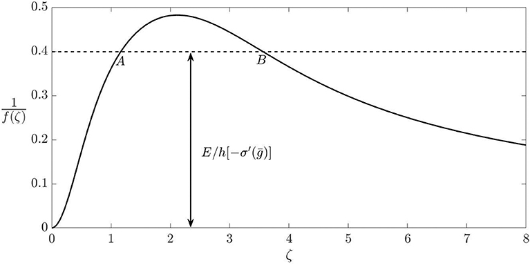
Figure 2. Dimensionless layer compliance as a function of wavenumber for an incompressible elastic layer bonded to arigid foundation. For a given value of E/h[−σ′(ḡ)] satisfying condition (6), wavenumbers in the range ζA < ζ < ζB are unstable.}.
The mean elastic strain energy per unit area associated with the deformation (3) is
The elastic strain energy for more general displacement distributions can be obtained by writing u(ξ, η) as a double Fourier series or Fourier transform and convoluting the resulting transform with (5).
Stability Criterion
If both surfaces are plane [i.e., smooth], the state u(ξ, η) = 0, g(ξ, η) = ḡ, σ(ξ, η) = σ(ḡ) is clearly an equilibrium state, but it will be unstable to small sinusoidal perturbations of dimensionless wavenumber ζ if there exists any ζ such that
The critical wavenumber is defined by the maximum of the curve in Figure 2, from which we deduce that the uniform solution will be unstable if and only if −σ′(ḡ) > E/0.482h.
Solution Method
More general displacement distributions for a square domain 0 < x < L, 0 < y < L can be written in the form
and equation (5) can then be used to obtain the mean strain energy per unit area U as
where
Adding the corresponding interface energy from equation (2), we obtain the total potential energy Π, which must be a minimum at a stable equilibrium state. We used the gradient descent method to identify the values of the Fourier coefficients Amn for a local energy minimum. Notice that the upper limit N must be chosen so as to provide an adequate number of integration points in the evaluation of Γ.
Results for Smooth Surfaces
If the two surfaces are smooth, the uniform state is always an equilibrium solution at which energy gradients are zero, and since the material is incompressible [ν = 0.5], this corresponds to u(ξ, η) = 0. Even when the criterion (6) is satisfied, the numerical solution may remain at the uniform state unless some small perturbation is introduced.
We used the traction law
(Maugis, 2013) derived from Lennard-Jones molecular force law (Jones, 1924), where ε is an interatomic length scale and Δγ = γ(ε) is the interface energy per unit volume at the equilibrium spacing g = ε. The maximum tensile traction occurs at g = 31/6ε and is of magnitude σ0 ≈ 1.06Δγε.
If the maximum negative slope satisfies the condition
there will exist a bounded range g1 < ḡ < g2 in which the uniform solution is unstable. Also, for a value of ḡ strictly within this range, there will exist a range of unstable wavenumbers ζA < ζ < ζB, including but not limited to ζ ≈ 2.1. This range can be identified by drawing a horizontal line at the height E/h[−σ′(ḡ)] in Figure 2 as shown, and finding its intersection with the curve.
We start the solution procedure with a value of ḡ outside the unstable range and then change ḡ by small increments, using the solution at the previous step as an initial guess for the gradient descent solution. This is expected to mimic the behavior of the physical system under controlled displacement conditions. Numerical noise might also be expected to emulate the effect of noise [e.g., vibration] in an experimental system.
We characterize the inverse thickness of the layer by the dimensionless parameter
Figure 3 compares a typical relation between the mean traction and the mean gap [approach] ḡ with the local traction law (1) for the case where β = 0.25. The domain size was chosen so as to define a fundamental wavenumber [e.g., ζ01] equal to 0.25, so that L = 8πh. Results are shown for both separation dḡ/dt > 0 and approach dḡ/dt < 0. In each case, the uniform state is preserved up to the appropriate stability boundary [denoted by A and B, respectively], but the non-uniform solution then persists significantly beyond the point at which the uniform solution reverts to stability. We deduce that even in the stable range there exist local energy minima corresponding to non-uniform states, and that these states are separated from the lower energy uniform state by energy barriers.
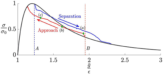
Figure 3. Mean traction as a function of mean gap ḡ for a smooth layer for β = 0.25 and domain size L = 8πh, showing instabilities during approach and separation. The Lennard-Jones law (1) is shown in black. The dashed lines A, B define the region in which the uniform traction solution is unstable.
Notice that both the approach and separation curves in Figure 3 are approximately straight lines with slope close to the critical slope defined by (6).
The non-uniform deformation states are characterized by the development of regular patterns. Figures 4A–C shows contours of local gap g(x, y) corresponding to the points on the approach curve labeled (a), (b) and (c) in Figure 3. A “labyrinth” [i.e., a connected system of passageways (high g) separated by walls of “contact” (low g)] develops at the onset of instability (a) and then morphs into an inverse labyrinth at (b) and into an array of isolated regions of separation [“holes”] at (c).
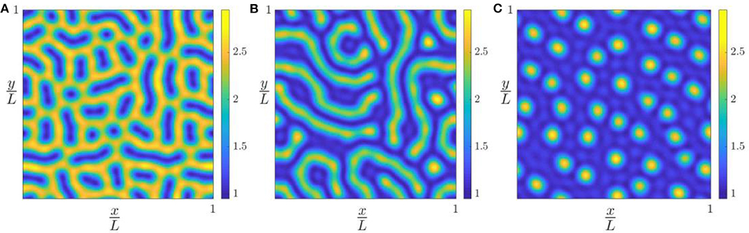
Figure 4. Contour plot of the gap g(x, y) during approach at points (A–C) in Figure 3.
Figures 5A–C shows the same results in Fourier transform space. In all cases we see high values clustered near the most unstable wavenumber ζ = 2.1 and the distribution is axisymmetric within the limits of statistical variance, indicating that the pattern is statistically isotropic.
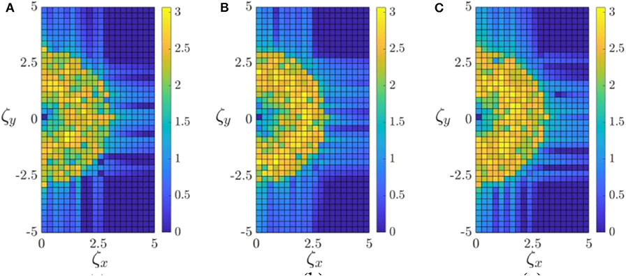
Figure 5. Fourier transform of g(x, y) from Figures 4A–C.
Effect of Surface Roughness
We assume that the surface is rough with a power spectral density [PSD] of the form
where B is a constant, H is the Hurst exponent, here taken as H = 0.2, and ζ1, ζ2 define the range of dimensionless wavenumbers in the spectrum, outside which the spectral content is zero. For the finite domain L × L, a realization of this PSD can be written as
where u0(x, y) describes the deviation of the surface from the mean plane in the undeformed state, and
The magnitudes of the coefficients |Bmn| were chosen so as to ensure that the resulting surface PSD was of the form (13) and the corresponding arguments [phases] were chosen randomly.
With this definition, the gap can be written
where u(x, y) is given by (7). Notice that we arbitrarily assign the value B00 = 0, so that the roughness makes no contribution to the mean gap. The interface energy is then determined from (2) and the constants Amn are chosen so as to minimize Π as in the smooth surface case.
A Two-Scale Approximation
We anticipate that the wavelengths in the roughness spectrum will generally be significantly smaller than the layer thickness, and this suggests the possibility of a scale-separation approach. Compared with the roughness scale, the thickness of the layer is large, so local effects can be approximated by those in a corresponding half space. The effect of the roughness, as compared with a corresponding smooth surface, can therefore be described in terms of a modified traction law.
An inductive method for estimating this law is described in (Joe et al., 2018). If the modified traction law σM(g, ζ0) is known for a surface with spectral content only in ζ0 < ζ < ζ2, where ζ0 > ζ1, the corresponding law for σM(g, ζ0−δζ) can be obtained by convoluting σM(g, ζ0) with the additional roughness tranche ζ0 − δζ < ζ < ζ0. Successive applications of this technique allow us to determine the modified law for the entire spectrum. In Joe et al. (2018), this procedure was implemented using discrete tranches of the spectrum, but the same approach can be used to develop a partial differential equation for σM(g, ζ), following the methodology of Persson (2001). The modified traction law for the complete roughness spectrum is then defined by σM(g) = σM(g, ζ1).
On the scale of the layer thickness, the effect of the surface roughness can then be approximated by using σM(g) in place of equation (1), and treating the layer surface as smooth.
Results
The two-scale approximation is likely to be most accurate when the most unstable wavenumber ζ ≈ 2.1 is much smaller than the smallest wavenumber ζ1 in the PSD [recall that wavenumbers are normalized by the layer thickness h]. However, this degree of scale separation is difficult to achieve in a direct numerical simulation. Figure 6 shows the relation between mean traction and mean gap for an incompressible elastic half space with roughness of the form (13) with ζ1 = 6.5, ζ2 = 8.0 and height variance
Barber (2018). In this figure, we compare two methods of solution: (i) a direct numerical solution of the problem [solid line] by minimizing the total energy for a gap defined by (16) using the Lennard-Jones traction law and (ii) a solution in which the layer is smooth [u0(x, y) = 0], but the traction law is modified to describe the effect of roughness [circles]. The agreement is clearly extremely good. The advantage of using the modified traction law is that the deformation of the layer can then be adequately described on a much coarser grid, or equivalently, by a more severely truncated Fourier series, and this is particularly useful if the spectral range [ζ1, ζ2] is broad.
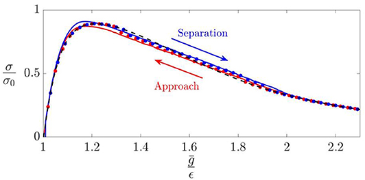
Figure 6. Mean traction as a function of mean gap ḡ for a layer with fine-scale roughness defined by equation (14) with β = 0.35, ζ1 = 6.5, ζ2 = 8.0 and . The solid lines correspond to a direct numerical solution for the rough surface using the Lennard-Jones traction law, whilst the circles were obtained by approximating the effect of roughness through a modified traction law σM(g) (Joe et al., 2018). [shown here as a dashed line].
Identifying Instability Effects
The argument of the previous section suggests that pattern instabilities should occur if and only if the maximum slope of the modified traction law [σM(ḡ)] satisfies the condition (11) — i.e.,
The modified traction law σM(ḡ) is independent of h, so instabilities are more likely for thicker layers, always assuming the finite linear dimensions of the interface are sufficient to accommodate a wavelength in the unstable range.
In some cases, pattern instabilities can be detected by examining the corresponding contour plots for g(x, y). For example, Figure 7A shows the contour plot for the actual rough surface during separation at a mean gap ḡ = 1.4, and Figure 7B shows the corresponding pattern predicted for a smooth surface with the modified traction law. There is some blurring of the observed patterns, but the overall morphology is clearly similar.
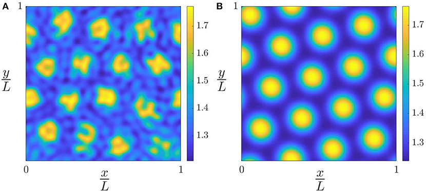
Figure 7. (A) Contour plot of gap g(x, y) at a point in the unstable range for β = 0.5 and roughness defined by ζ1 = 6, ζ2 = 8 and . (B) The corresponding plot for a smooth surface using the modified traction law.
However, if the roughness amplitude is larger, patterns become more blurred, a typical example being shown in Figure 8A. In this case, detection of instability from gap contours is more difficult, but the corresponding Fourier plot of Figure 8B clearly shows substantial spectral content in the unstable range near ζ = 2.1. This suggests that we might quantify the extent of pattern formation in the numerical solution for the rough surface using the dimensionless parameter , where is the variance of that part of the gap PSD that lies in the unstable range in the “smooth” solution, identified in Figure 2. We assume here that the roughness PSD has no content in this wavenumber range, since otherwise it would be difficult to distinguish the separate effects of instability and roughness.
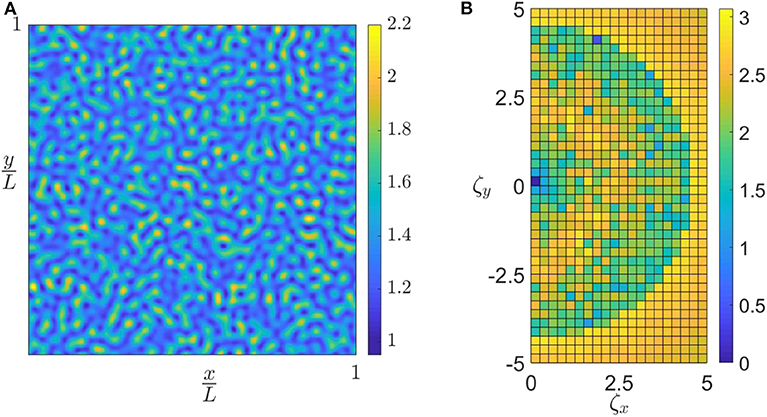
Figure 8. (A) Contour plots of gap g(x, y) in the unstable range for β = 0.5 and roughness defined by ζ1 = 4.5, ζ2 = 8 and . (B) Fourier domain plot for the gap distribution g(x, y) from (A).
In Figure 9 we plot , obtained from the numerical solution, as a function of the maximum negative slope of the modified traction law , normalized by the corresponding expression for the Lennard-Jones law. Each set of points corresponds to a different value of the lower wavenumber of the roughness ζ1 = 4.5:0.5:6.5 and a range of roughness variances . Results were obtained under both approach and separation conditions, but no significant difference was observed. The vertical dashed line in Figure 9 corresponds to the criterion (18), below which the two-scale approximation would predict , though the direct numerical results exhibit a level of noise as one might expect. However, the results exhibit a remarkable level of consistency, showing that is a very good indicator of the effect of roughness on the instability, and more generally that the two-scale approach to the layer problem defines a good approximation to important features of the system behavior.
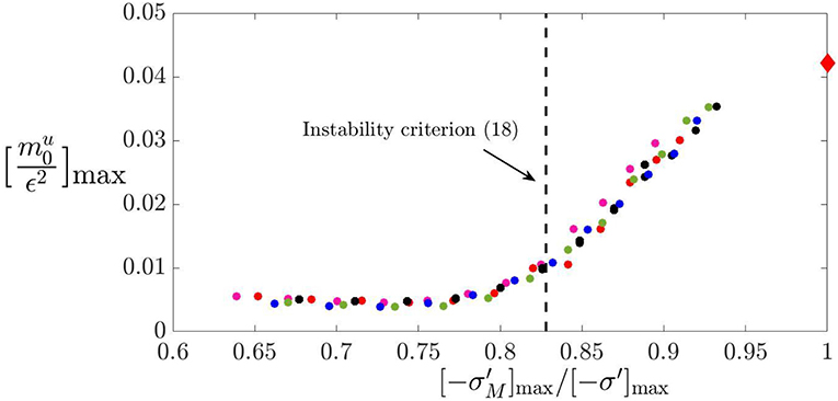
Figure 9. Normalized spectral content for the gap g(x, y) in the unstable wavenumber range as a function of the maximum negative slope of the modified traction law . Consistency between several roughness spectra shows that is a good indicator of the effect of roughness on instability. The point at the top right defines for a smooth layer.
Conclusions
If a smooth elastic layer is placed close to a plane surface, elastic instabilities due to adhesive tractions lead to the development of patterns, and to a modification of the traction-separation law. However, roughness with RMS amplitude comparable with the range of the adhesive force law can have a significant effect on this process. Here we have described a model for analyzing the contact of both rough and smooth surfaces using a double Fourier series.
We also developed a two-scale approximation to the rough contact behavior, by (i) estimating the effect of roughness on the mean traction between two half spaces, using a previously published method (Joe et al., 2018), and then (ii) using this modified traction law in the analysis of a smooth elastic layer. Results show that this gives a very good approximation to the traction-separation law obtained by direct numerical simulation. In particular, the development of patterns is predicted if the maximum slope of the modified traction law satisfies the inequality (18) and the corresponding results correlate extremely well with a criterion based on the spectral content in the unstable range from the numerical solution.
Local layer deformations decay spatially at a rate linked to the layer thickness, so this method is expected to give good predictions for bodies of finite size sufficient to support wavelengths in the unstable range.
Data Availability Statement
All datasets presented in this study are included in the article/ supplementary files.
Author Contributions
JJ wrote the first draft of the manuscript, performed the statistical analysis and organized the database. JB wrote sections of the manuscript. All authors contributed to conception and design of the study, manuscript revision, read, and approved the submitted version.
Conflict of Interest
The authors declare that the research was conducted in the absence of any commercial or financial relationships that could be construed as a potential conflict of interest.
References
Arun, N., Sharma, A., Shenoy, V. B., and Narayan, K. (2006). Electric-field-controlled surface instabilities in soft elastic films. Adv. Mater. 1, 660–663. doi: 10.1002/adma.200502199
Bhandaru, N., Sharma, A., and Mukherjee, R. (2017). Programmable nanopatterns by controlled debonding of soft elastic films. ACS Appl. Mater. Interfaces 9, 19409–19416. doi: 10.1021/acsami.6b09127
Ciavarella, M., Joe, J., Papangelom, A., and Barber, J. R. (2019). The role of adhesion in contact mechanics. J. R. Soc. Interface 16:20180738. doi: 10.1098/rsif.2018.0738
Davis-Purcell, B., Soulard, P., Salez, T., Raphael, E., and Dalnoki-Veress, k. (2018). Adhesion-induced fingering instability in thin elastic films under strain. Eur. Phys. J. E 41:36. doi: 10.1140/epje/i2018-11643-6
Ghosh, A., Bandyopadhyay, D., Sarkar, J., and Sharma, A. (2017). Hierarchical micro-and nanofabrication by pattern-directed contact instabilities of thin viscoelastic films. Phys. Rev. Fluids 2:124004. doi: 10.1103/PhysRevFluids.2.124004
Ghosh, A., Bandyopadhyay, D., and Sharma, A. (2016). Influence of the mutable kinetic parameters on the adhesion and debonding of thin viscoelastic films. J. Colloid Interface Sci. 477, 109–122. doi: 10.1016/j.jcis.2016.05.036
Ghosh, A., Bandyopadhyay, D., and Sharma, A. (2018). Micro-patterning of coatings on a fiber surface exploiting the contact instabilities of thin viscoelastic films. Phys. Fluids. 30:114101. doi: 10.1063/1.5053797
Gonuguntla, M., Sharma, A., Mukherjee, R., and Subramanian, S. A. (2006a). Control of self-organized contact instability and patterning in soft elastic films. Langmuir 22, 7066–7071. doi: 10.1021/la0600696
Gonuguntla, M., Sharma, A., and Subramanian, S. A. (2006b). Elastic contact induced self-organized patterning of hydrogel films. Macromolecules 39, 3365–3368. doi: 10.1021/ma0600411
Hannah, M. (1951). Contact stress and deformation in a thin elastic layer. Quart. J. Mech. Appl. Mathematics 4, 94–105. doi: 10.1093/qjmam/4.1.94
Joe, J., Thouless, M. D., and Barber, J. R. (2018). Effect of roughness on the adhesive tractions between contacting bodies. J Mech. Phys. Solids 118, 365–373. doi: 10.1016/j.jmps.2018.06.005
Jones, J. E. (1924). On the determination of molecular fields.—II. from the equation of state of a gas. Proc. R. Soc. London Series A 106, 463–477. doi: 10.1098/rspa.1924.0082
Maugis, D. (2013). Contact, Adhesion and Rupture of Elastic Solids. New York, NY: Springer. doi: 10.1007/978-3-662-04125-3
Mönch, W., and Herminghaus, S. (2001). Elastic instability of rubber films between solid bodies. EPL 53:525. doi: 10.1209/epl/i2001-00184-7
Mukherjee, R., Pangule, R. C., Sharma, A., and Banerjee, I. (2007). Contact instability of thin elastic films on patterned substrates. J. Chem. Phys. 127:064703. doi: 10.1063/1.2752499
Persson, B. N. J. (2001). Theory of rubber friction and contact mechanics. J. Chem. Phys. 115, 3840–3861. doi: 10.1063/1.1388626
Sahoo, S., Bhandaru, N., and Mukherjee, R. (2019). Reversible morphological switching and deformation hysteresis in electric field mediated instability of thin elastic films. Soft Matter 15, 3828–3834. doi: 10.1039/C8SM02622J
Sarkar, J., and Sharma, A. (2010). A unified theory of instabilities in viscoelastic thin films: from wetting to confined films, from viscous to elastic films, and from short to long waves. Langmuir 26, 8464–8473. doi: 10.1021/la9049007
Sarkar, J., Sharma, A., and Shenoy, V. B. (2008). Electric-field induced instabilities and morphological phase transitions in soft elastic films. Phys. Rev. E 77:031604. doi: 10.1103/PhysRevE.77.031604
Sarkar, J., Shenoy, V., and Sharma, A. (2004). Patterns, forces, and metastable pathways in debonding of elastic films. Phys. Rev. Lett. 93:018302. doi: 10.1103/PhysRevLett.93.018302
Keywords: contact mechanics, surface roughness, adhesion, elastic layers, patterning
Citation: Joe J, Thouless MD and Barber JR (2020) Effect of Surface Roughness on Adhesive Instabilities for the Elastic Layer. Front. Mech. Eng. 6:31. doi: 10.3389/fmech.2020.00031
Received: 19 March 2020; Accepted: 27 April 2020;
Published: 22 May 2020.
Edited by:
Valentin L. Popov, Technical University of Berlin, GermanyReviewed by:
Alexander Filippov, Donetsk Institute for Physics and Engineering, UkraineElena Torskaya, Institute for Problems in Mechanics (RAS), Russia
Copyright © 2020 Joe, Thouless and Barber. This is an open-access article distributed under the terms of the Creative Commons Attribution License (CC BY). The use, distribution or reproduction in other forums is permitted, provided the original author(s) and the copyright owner(s) are credited and that the original publication in this journal is cited, in accordance with accepted academic practice. No use, distribution or reproduction is permitted which does not comply with these terms.
*Correspondence: Junki Joe, jkjoe@umich.edu