Experimental and numerical simulation study on coupling tripping of partial trapezoidal threaded casing head and casing coupling
 Jun Zhang1
  Mingzhi Li
- 1Engineering Technology Research Institute of Xinjiang Oilfield Company, Karamay, Xinjiang, China
- 2State Key Laboratory of Explosion Science and Safety Protection, Beijing Institute of Technology, Beijing, China
Casing connection is a common connection method in oil and gas reservoir production, and the tripping of casing will seriously hinder the production process. To study the casing tripping process and the minimum tensile load required for casing tripping under different loosening buckle states, three kinds of casing tripping tensile tests were carried out. The thread morphology of the casing head and casing coupling was analyzed by local cutting at the end of the experiment, and the thread failure area was analyzed by scanning electron microscope, and then other loosening states were studied and analyzed using numerical simulation. The research results show that as the number of loosening buckles increases, the minimum tensile load required for the casing head and casing coupling to trip decreases. The observation of the thread shape shows that the thread part of the casing head was seriously damaged. Scanning electron microscopy results show that the fracture mode at the thread of the casing head is ductile fracture. Numerical simulation results show that the maximum stress area during the tripping process is at the contact position between the thread heads. Based on the experimental and numerical simulation results, the relationship between the number of casing loosening and the minimum tensile load required for casing tripping is obtained. The research results can be used as the experimental and theoretical basis for the investigation of casing tripping accidents and can also provide experimental reference for the design of the next-generation of casing.
1 Introduction
Threads are widely used in real life. When the thread fails, it will cause severe damage to the system. Therefore, the failure of threads in various forms (Albdiry and Almensory, 2016; Mahmoud et al., 2016; Cirimello et al., 2017) has always been a hot issue in thread research. At present, scholars mainly use the methods of experimental research, theoretical research, and numerical simulation to study the thread.
Experimental research is the basis for thread failure research. Many scholars have obtained relevant results of thread failure under different conditions through experimental research. Among these studies, there are many studies on bolt fracture (Li et al., 2023; Yao and Zhang, 2023; Yapici et al., 2023). Duan and Joshi (2011) conducted full-scale tensile fracture experiments on steel tie rods with triangular thread connections and trapezoidal thread connections to test the maximum fracture load under different numbers of meshing thread turns. Experimental results show that the tensile breaking strength of trapezoidal threads is greater than that of triangular threads. Soussi et al. (2022) studied the ultimate load of nut threads with insufficient meshing length through experimental research and predicted the maximum load capacity of the thread. Through experiments and numerical simulation studies (Wang et al., 2020), found that improper buckle position of casing will lead to insufficient connection strength, resulting in loss of thread bearing area and ultimately causing casing tripping events. Regarding the study of the self-loosening behavior of threads (Zhang et al., 2018), studied the influence of lateral cyclic loads on the self-loosening behavior of bolt threaded connections through experiments and numerical simulation methods. Research results show that wear at the thread is one of the reasons for the self-loosening behavior of threaded connections. Yu et al. (2022) studied the loosening and fatigue fracture of mixed thread connections with different materials under cyclic load through experimental and numerical simulation methods. Nah et al. (2014) experimentally studied the influence of thread surface coating thickness and coating type on thread relaxation after clamping. Yang and Nassar (2011) proposed a thread self-loosening model under load through experiments and theoretical analysis. Tendo et al. (2001) studied the stress relaxation caused by creep deformation at the bolted joint of high-strength stainless steel plate using experiment and numerical simulation.
In related simulation studies of thread structures (Duan and Joshi, 2013), studied the structural response of the thread under different axial loads through numerical simulation. The results showed that the maximum stress of the thread occurs at the root of the meshing teeth, and the maximum contact pressure is between the medium diameter and the small diameter of the external thread. Liao et al. (2011) compared different models through numerical simulation and concluded that the damage and fracture prediction model needs to consider stress triaxiality. Lin et al. (2023) studied the relationship between tightening torque and bolt tension through numerical simulation and analyzed the influence of friction coefficient on the tightening coefficient value.
In the numerical simulation of tripping (Zhu et al., 2013; Zhu, 2015), used the finite element analysis method to study that the cause of the drill pipe thread gluing failure accident was sealing failure due to insufficient tightening torque and drill pipe suspension. Gao and Shi (2013) found through numerical simulation research that the pull-out failure of threaded connections begins at the first or second tooth of the thread end. Yang et al. (2021) obtained through numerical simulation research that the thread shear area will decrease during the bolt tripping process. In the numerical simulation of thread loosening (Gong et al., 2019), obtained through numerical simulation and experimental methods that the main influencing factors of thread loosening are preload force, friction coefficient of thread and supporting surface, clamping length, and fitting tolerance. Zhang et al. (2019) experimentally verified the feasibility of the finite element model to study the self-loosening of bolt joints caused by thread wear under lateral load and studied the influence mechanism of thread wear on the self-loosening of bolt connections through numerical simulation. IZUMI et al. (2007) studied the mechanism of the thread loosening process caused by surface slip of micro-bearing by numerical simulation. Gong et al. (2021) revealed the mechanism of local slip accumulation in threads through numerical simulation and experimental verification and verified the existence of critical self-loosening. Liu et al. (2021) obtained through numerical simulation and experiment that bolt joints with long meshing and fine thread had better anti-loosening performance.
Theoretical research is an explanation and supplement to experimental research. Aldana and Moore (2022) used a new reduced-order modeling method to calculate the behavior of three rods connected by two axially aligned threaded joints under different loads. Five states of the three rods under different loads were obtained. It was also studied that the intensity of the effect of loosening one joint on the other depends on the applied load and initial torque. Through theoretical research and experimental verification (Nassar and Xianjie, 2007; Nassar and Yang, 2008), obtained equations that can predict the torque and clamping force between threads and bearings and calculation equations between thread friction, pitch, and torque components. Mo et al. (2020) proposed a numerical calculation model for thread anti-loosening and verified its reliability through experiments. The research results show that the load has a more significant impact on the anti-loosening performance. Moore (2019) proposed a mechanical response model for bolt joint loosening when axial loads are applied that considers torque and joint stiffness.
In the studies by the scholars mentioned above, most of the loads acting on the threads were cyclic loads, and the thread tripping problem under the action of a single load was not studied. In addition, the threads studied are mainly circular threads, and there are few studies on trapezoidal threads. This paper uses experimental methods to study the tensile load required for tripping trapezoidal threaded casing under three working conditions. The cross-section of the damaged thread was analyzed, and samples from the damaged area were sampled for scanning electron microscopy analysis, and the damage mode during the thread tripping process was obtained. By comparing with the experimental results, the effectiveness of the numerical simulation method in studying the tripping problem of trapezoidal threads was verified, and the tensile load required for casing tripping under other working conditions was obtained using the numerical simulation method. Finally, by combining the results of experiments and numerical simulations, the tensile load calculation formula required for the tripping of the trapezoidal thread casing head and casing coupling was obtained. The research results can provide an experimental reference for analyzing oil well casing accidents in the oil and gas industry.
2 Experimental materials and experimental settings
2.1 Experimental materials
The specifications of the casing head and casing coupling used in the experiment are 13–3/8 in. The diameter of the casing head is 339.7 mm, and the wall thickness is 9.7 mm. The diameter of the casing coupling is 339.7 mm, and the wall thickness is 10 mm. The casing head and casing coupling are shown in Figure 1. The threads of the casing head and casing coupling are trapezoidal threads with a thread tooth height of 0.062 in, a pitch of 0.2 in, and a taper of 1/16.
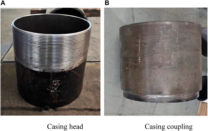
FIGURE 1. (A) Casing head (B) Casing coupling.
The material of the casing head is J55 steel, with a yield strength of 380 MPa and a tensile strength of 518 MPa. The material of the casing coupling is 30CrMo steel, with a yield strength of 758 MPa and a tensile strength of 862 MPa. The chemical compositions of casing heads and casing couplings are shown in Table 1.

TABLE 1. Main chemical components of casing heads and casing couplings.
2.2 Experimental settings
Three working conditions were designed in the experiment to test the tripping tensile load of the casing head and casing coupling. The working conditions were as follows: loosening the casing head and casing coupling by half a buckle, loosening one buckle, and loosening three buckles. The experiment first uses a machine to completely tighten the casing head and casing coupling, then inverts the casing coupling the relevant number of turns according to the number of buckles to be loosened, and then the casing head and coupling were installed in the composite loading experimental system (maximum tensile load is 2,500 t) as shown in Figure 2A for the experiment. The schematic diagram of the experimental process is shown in Figure 2B. The composite loading experimental system provides tensile load on the casing head and casing coupling. After the experiment starts, stretch the casing head and coupling until they are tripped. After the test, the casing head and casing coupling were cut to observe the damage results at the thread, and samples were taken for scanning electron microscopy to analyze the thread damage mode. The model of the scanning electron microscope is TESCAN MIRA LMS + Quantax 200 XFlash 6|60.
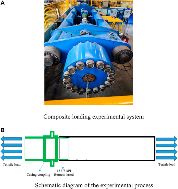
FIGURE 2. (A) Composite loading experimental system (B) Schematic diagram of the experimental process.
3 Experimental results
The experimental results mainly include tensile test results, thread damage results, and thread damage analysis. The tensile test results are the minimum tensile load required when the composite loading system stretches the casing head and casing coupling to tripping. The damage results at the thread are the analysis of the damage results at the threaded parts of the casing head and casing coupling. The tensile tripping analysis of the casing head and casing coupling uses a scanning electron microscope to analyze the thread damage and then infers the entire tripping process.
3.1 Tensile test results
The tensile test results are shown in Figure 3. It can be seen that more threads are exposed at the connection position between the casing head and the casing coupling. The tensile loading during the experiment is shown in Figure 4. The tensile force of the composite loading system was loaded at a constant speed. When the casing head and casing collar were pulled apart, the tensile force of the composite loading system would also decrease rapidly. During the loading process, the loading rate of the tension was 120 kips/min, which was 533.76 kN/min.
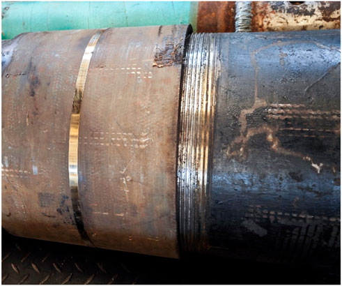
FIGURE 3. Tensile test results.
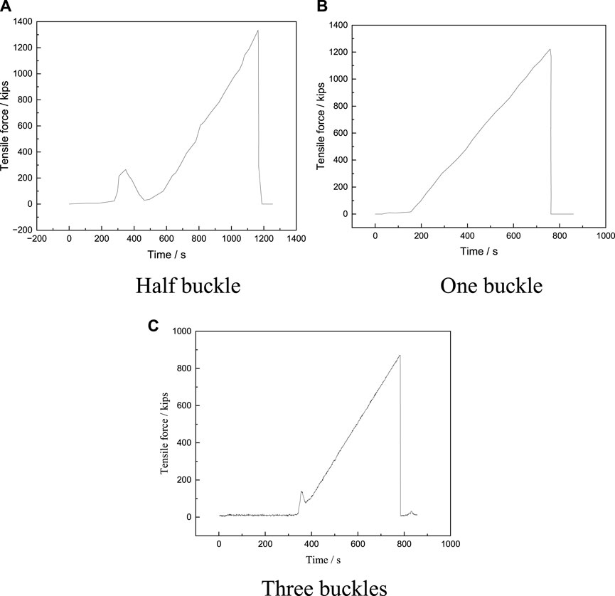
FIGURE 4. Tensile force change diagram during the stretching process of the composite loading system. (A) Half buckle (B) One buckle (C) Three buckles.
The tensile test results are shown in Table 2. The relationship between the minimum tensile load for tripping and the number of loose buckles in the experiment is shown in Figure 5. It can be seen that with the increase in the number of loosenesses of the casing head and casing coupling, the minimum load required for the two to trip continuously decreases. When the number of loose buckles increases from half a buckle to one buckle, the minimum load required for tripping decreases from 5,933 kN to 5,434 kN, a decrease of 8.4%. When the number of loose buckles increases from one to three, the minimum load required for tripping decreases from 5,434 kN to 3,876 kN, a decrease of 28.7%. The main reason for this phenomenon is that the number of threads connecting the casing head and the casing coupling decreases as the number of loose threads increases (Wang et al., 2020). At the same time, due to the existence of the taper, the contact area between threads will also decrease as the number of loose threads increases.
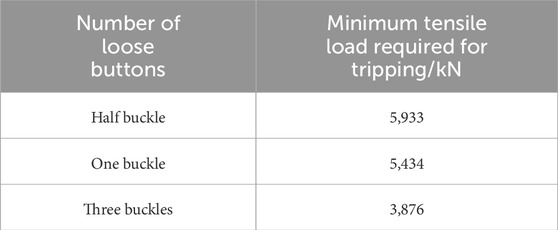
TABLE 2. Tensile test results.
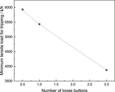
FIGURE 5. The relationship between the minimum tensile load for casing tripping and the number of loose buttons.
3.2 Damage results at the thread
The experimental results of the casing head and casing coupling are shown in Figure 6. It can be seen that there are many broken filaments of different lengths at the casing head, and there are also many broken filaments on the casing coupling. The broken filaments can be inferred that the threads were broken during the tripping process of the casing head and the casing coupling. At the same time, it can be concluded from the different lengths of the filaments that the thread breaks are partial breaks and not complete breaks. The black substance on the thread surface is the lubricating oil used in threaded connections.
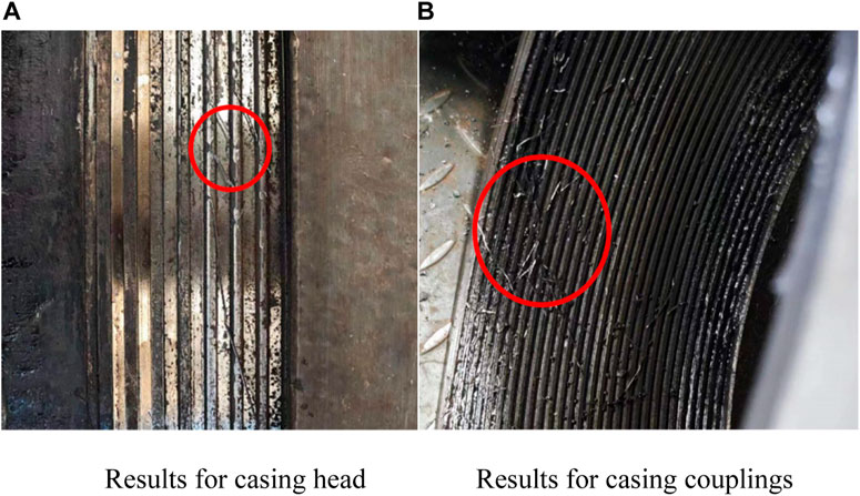
FIGURE 6. (A) Results for casing head (B) Results for casing couplings.
In order to further observe the damage of the trapezoidal threads of the casing head and casing coupling, wire cutting was performed on the threaded part. The cut entities are shown in Figures 7, 8. Figure 7 shows the damage results and cross-section of the casing head. From Figure 7A, it can be seen that the overall damage to the thread is small. At the same time, because the tooth height and pitch of the thread are small, the damage is almost invisible to the naked eye. In Figure 7B, it can be seen that the damage results in the thread. First, there are unbroken filaments at the thread, and second, the top of the thread is deformed. It can be seen that there is plastic deformation and partial fracture at the top of the thread of the casing head.
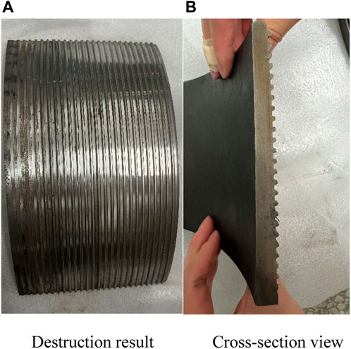
FIGURE 7. (A) Destruction result (B) Cross-section view.
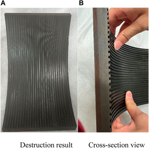
FIGURE 8. (A) Destruction result (B) Cross-section view.
Figure 8 shows the damage results and cross-section of the casing coupling. It can be seen from Figure 8A that the thread is relatively complete as a whole, and no signs of damage are found. From Figure 8B, we can see that the cross section of the thread is very intact, and no deformation can be seen.
It can be seen from the above results that during the tripping process of the casing head and casing coupling, the damage was mainly concentrated on the casing head part, and almost no damage was found on the casing coupling. The main reason for this phenomenon is that the strength of the casing head is lower than that of the casing coupling. During the tension tripping process, the thread belonging to the casing head will first undergo plastic deformation, and at the same time, local threads will break to form filaments. The main reason for the different lengths of the filaments is that during the experiment, the casing was placed horizontally, which was affected by gravity. Subsequently, the fit between the threads will produce a small amount of offset due to the gap existing in the loosening.
3.3 Analysis of the tripping process
In order to determine the damage mode of the thread at the casing head, the damaged part of the casing head was sampled and observed using a scanning electron microscope. The SEM observation position is shown in Figures 9A, B, and the SEM results are shown in Figure 9C. The observation scales for this position are 10 μm, 5 μm and 1 μm. It can be seen that the microstructures at different scales are dominated by dimples, so it can be inferred that the wire drawing formation method of thread damage is ductile fracture.
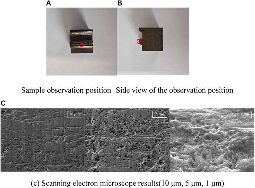
FIGURE 9. Scanning electron microscope diagram of the damaged part of the casing head. (A) Sample observation position (B) Side view of the observation position, (C) Scanning electron microscope results (10 μm, 5 μm and 1 μm).
Based on the above analysis, the whole process of tripping the casing head and casing coupling under tensile load can be obtained. Under the action of tensile load, the threads of the casing head and casing coupling begin to interact. The threads of the low-strength casing head subsequently undergo plastic deformation. As the tensile load continues to increase, ductile fracture occurs in the plastic deformation area of the thread, eventually causing the casing head and casing coupling to trip.
4 Numerical simulation setup
Through experimental research, the minimum tensile load required for the casing head and casing coupling to trip under three different working conditions was obtained. However, in reality, there will be a variety of working conditions for the connection between the casing head and the casing coupling. Therefore, the minimum tensile load required for tripping under more working conditions is simulated through numerical simulation, and then combined with the experimental data, the relationship between the minimum tensile load required for tripping of the casing head and casing coupling under different connection conditions can be obtained.
4.1 Numerical model setup
The setting of the numerical model should be consistent with the actual object. Considering that there are too many threads on the casing head and casing coupling, and the thread tooth height is small relative to the wall thickness of the casing head (1.5:10), it is not conducive to meshing. At the same time, the structure of the casing head and the casing coupling is symmetrical to the axis position. Finally, considering the practices of other scholars (Wang et al., 2020), the numerical model is established as the cross-section part of the solid model. The specific numerical model is shown in Figure 10. The number of threads in the model is 21. The parameters of the threads are the same as in Section 2 of this article. As shown in the figure, the red part is the casing head model, and the blue part is the casing coupling model. Hexahedral mesh is used in the modeling process, the mesh type is C3D8R. The boundary conditions of the model are set to make the entire model symmetrical about the z-axis, and the edge position of the casing head is fixed. The stretching position is arranged above the casing coupling.
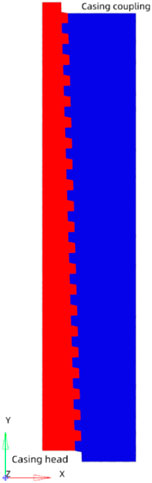
FIGURE 10. Numerical model diagram.
The commercial software Abaqus was used to perform numerical model calculations. Considering that there is a large deformation process, such as thread destruction, in the model calculation, the simulation algorithm adopts the explicit dynamics algorithm. The contact between the casing head and the casing coupling is set to ‘General contact (explicit),’ the friction formula is ‘Penalty’, and the friction coefficient is 0.3 (Swissi et al., 2019). The material model of the casing head and casing coupling is an elastic-plastic material model, and the specific parameters are shown in Table 3.
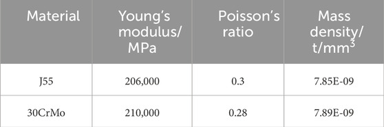
TABLE 3. Main parameters of each material.
4.2 Numerical model accuracy verification
Through comparative analysis with experimental results, the appropriate mesh size can be obtained, thereby ensuring the accuracy of numerical simulation and improving calculation efficiency. The experimental results when the casing head and casing coupling were loosened by one buckle were selected as a reference to verify the mesh size. The mesh has six sizes to choose from 0.05 mm, 1 mm, 2 mm, 3 mm, 4 mm, and 5 mm. The comparison of the minimum tensile load required for tripping simulated by meshes of different sizes and the experimental results is shown in Figure 11. It can be seen that as the mesh size decreases, the simulation results of the minimum tensile load required for the casing head and casing coupling to trip have decreased. When the mesh size is 1 mm, the simulation results are already close to the experimental results. The results of 0.5 mm are close to the results of 1 mm, but the time required for simulation will increase significantly. In order to perform numerical simulation more accurately and efficiently, the grid size is selected to be 1 mm.
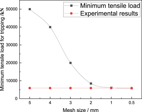
FIGURE 11. Comparison of the minimum tensile load required for tripping with different mesh sizes and experimental results.
After the mesh size of the numerical model is determined, the accuracy of the model needs to be verified by comparison with experimental results. The accuracy verification is mainly carried out from two aspects, namely, the minimum load required for model tripping and the damage result of the model mesh.
The comparison between the numerical simulation results and the experimental results of the minimum tensile load required for model tripping is shown in Table 4. It can be seen that when the number of loose buckles is half, the numerical simulation results are larger than the experimental results first, while when the number of loose buckles is one and three buckles, the numerical simulation results are relatively smaller. From the perspective of errors, the errors in the three working conditions are 167 kN, 234 kN, and 176 kN, respectively. The error ranges are all within 5%, which is an acceptable error. The model damage results are shown in Figure 12. It can be seen that the threads of the casing head are broken, but the threads of the casing coupling are intact, which is consistent with the experimental results. Through comparison of these two aspects, it can be considered that the error of the numerical simulation results is acceptable.
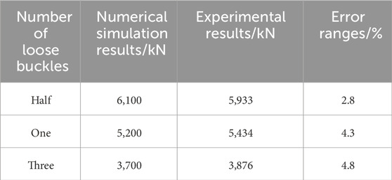
TABLE 4. Comparison of numerical simulation results and experimental results.

FIGURE 12. Numerical simulation results of loose one buckle working condition.
5 Numerical simulation result
After verifying the accuracy of the numerical simulation, numerical simulations were carried out under five working conditions of loosening two buckles, four buckles, five buckles, six buckles, and seven buckles between the casing head and the casing coupling. The stress distribution results at different positions of the casing head and casing coupling during the tripping process were studied, and the minimum tensile load required for tripping under different working conditions was also studied.
5.1 Tensile process analysis
By analyzing the stress distribution diagram, it can be obtained that the stress distribution of the casing head and casing coupling during the stretching process, and then understand the vulnerable locations of the casing head and casing coupling. Figures 13, 14 show the stress distribution diagrams in different states when the casing head and casing coupling are loosened by 1 and 7 buckles, respectively. It can be seen from the figure that the stress of the threaded part is larger than that of other parts, that is, the areas with the highest stress are concentrated in the threaded part. It can be seen from Figures 13A, B that the maximum stress area is concentrated in the thread root area. Figures 14A, B show that the maximum stress area is concentrated at the contact position between the casing head and the casing coupling thread, and there is also a maximum stress area at the thread root. Comparing Figures 13, 14, it can be seen that during the tension tripping process of the casing head and casing coupling, the maximum stress area is mainly the thread contact head position and the thread root. It can be seen from Figure 13C and Figure 14C that the thread fracture occurs in the area with the greatest stress, which is also the head position where the thread contacts.
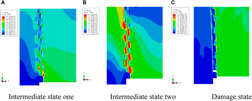
FIGURE 13. Stress distribution diagram of different states of loose one buckle. (A) Intermediate state one (B) Intermediate state two (C) Damage state.
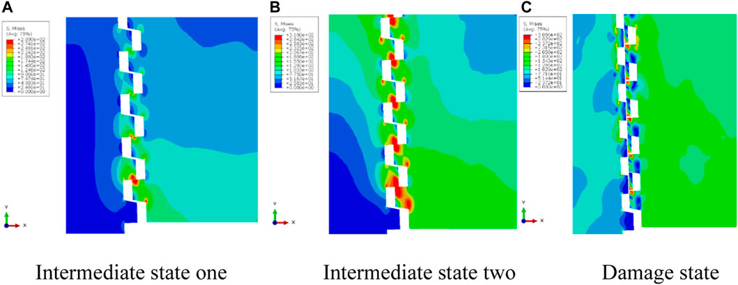
FIGURE 14. Stress distribution diagram of different states of loose seven buckle. (A) Intermediate state one (B) Intermediate state two (C) Damage state.
From the above analysis, it can be inferred that during the stretching process of the casing head and casing coupling, the stress is mainly concentrated on the thread part. The stress in the thread part is mainly concentrated at the thread root and the head position where the threads contact. When the thread strength is less than the tensile strength, the thread will be damaged, and the damage location will be at the head position where the thread contacts.
5.2 Simulation results of minimum tensile load for tripping
The simulation results of the tripping of the casing head and casing coupling under different working conditions are shown in Figure 15. It can be seen that both the casing head and the casing coupling can be fully tripped. The minimum tensile load required for tripping is shown in Table 5, and the line graph shown in Figure 16 can be obtained by processing it. It can be seen that as the number of loosening of the casing head and casing coupling increases, the minimum tensile load required for tripping continues to decrease.
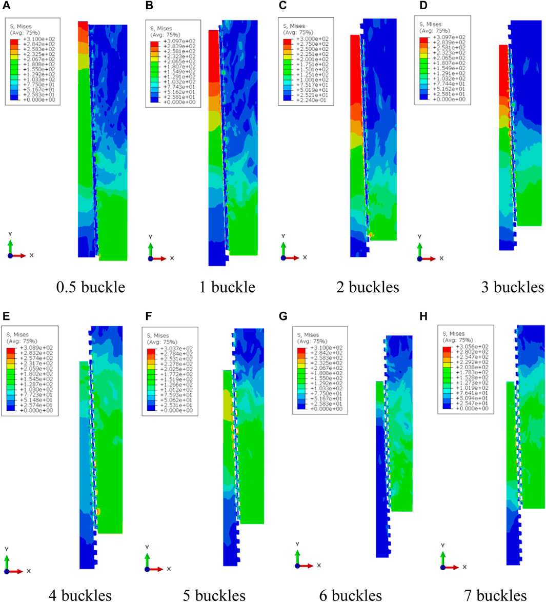
FIGURE 15. Simulation results of tripping of casing head and casing coupling under different working conditions. (A) 0.5 buckle (B) 1 buckle (C) 2 buckles (D) 3 buckles (E) 4 buckles (F) 5 buckles (G) 6 buckles (H) 7 buckles.
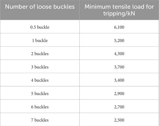
TABLE 5. Numerical simulation results under different working conditions.
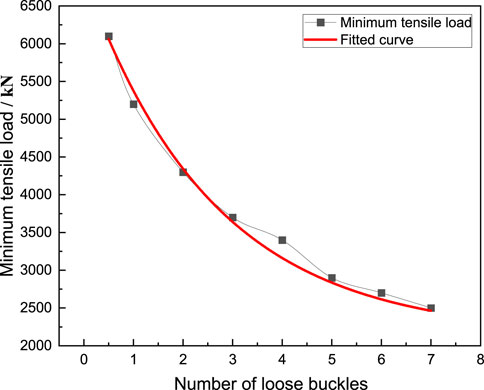
FIGURE 16. Change curve of the number of loose buckles and the minimum tensile load required for tripping.
By fitting the experimental and numerical simulation results in Figure 16, the relationship between the minimum tensile load
In previous research (Sacquepey and Spenlé, 1993), the minimum tensile load required for bolt tripping can be calculated using Eq. 2.
in the formula,
When the research object is bolted, the
In formula (3) A, B, and C are constants. Substituting the parameters of the casing head and casing coupling studied in this study into formula (3), the calculation formula of this study can be obtained, as shown in formula (4).
For different types of trapezoidal threaded casing, the minimum tensile load required for the casing head and casing coupling to trip can be obtained through experimental results and combined with Eq. 3. For the same trapezoidal threaded casing in this study, the minimum tensile load required can be calculated using Eq. 4.
6 Conclusion
This study conducted tripping experiments on casing heads and casing couplings under three different working conditions, observed the damage results at the casing threads, and conducted a scanning electron microscope analysis of the damage at the threads. The accuracy of the numerical simulation was verified based on the experimental results, and the tripping of the casing head and casing coupling under more working conditions was studied through numerical simulation. This study can draw the following conclusions.
(1) The minimum tensile load required for the casing head and casing coupling to trip is related to the number of loose buckles. The greater the number of buckles, the smaller the minimum tensile load required. When the number of loose buckles increases from seven buckles to half a buckle, the minimum load required for tripping increases from 2,500 kN to 5,933 kN.
(2) When the casing head and casing coupling are tripped, the most severely damaged part is the threaded part. The threaded portion will plastically deform and fracture, and the fracture form is ductile fracture.
(3) During the tension tripping process between the casing head and the casing coupling, the maximum stress area is the thread contact head position and the thread root position.
(4) Future research can conduct more tripping experiments on different types of casing heads and casing couplings to obtain a tripping prediction formula with a wider range of applications.
Data availability statement
The original contributions presented in the study are included in the article/Supplementary Material, further inquiries can be directed to the corresponding author.
Author contributions
JZ: Conceptualization, Methodology, Writing–original draft. CD: Supervision, Validation, Writing–review and editing. YL: Investigation, Resources, Visualization, Writing–review and editing. HD: Formal Analysis, Funding acquisition, Supervision, Writing–review and editing. MA: Data curation, Visualization, Writing–review and editing. ML: Data curation, Software, Validation, Writing–review and editing.
Funding
The author(s) declare financial support was received for the research, authorship, and/or publication of this article. The authors are grateful for the financial support provided by the National Key R&D Program of China (2022YFC3006302) and the National Natural Science Foundation of China (12202064).
Conflict of interest
Authors JZ, CD, YL, HD, and MA were employed by Engineering Technology Research Institute of Xinjiang Oilfield Company.
The remaining author declares that the research was conducted in the absence of any commercial or financial relationships that could be construed as a potential conflict of interest.
Publisher’s note
All claims expressed in this article are solely those of the authors and do not necessarily represent those of their affiliated organizations, or those of the publisher, the editors and the reviewers. Any product that may be evaluated in this article, or claim that may be made by its manufacturer, is not guaranteed or endorsed by the publisher.
References
Albdiry, M. T., and Almensory, M. F. (2016). Failure analysis of drillstring in petroleum industry: a review. Eng. Fail. Anal. 65, 74–85. doi:10.1016/j.engfailanal.2016.03.014
Aldana, S., and Moore, K. J. (2022). Dynamic interactions between two axially aligned threaded joints undergoing loosening. J. Sound. Vib. 520, 116625. doi:10.1016/j.jsv.2021.116625
Cirimello, P. G., Otegui, J. L., Carfi, G., and Morris, W. (2017). Failure and integrity analysis of casings used for oil well drilling. Eng. Fail. Anal. 75, 1–14. doi:10.1016/j.engfailanal.2016.11.008
Duan, W., and Joshi, S. (2011). Failure analysis of threaded connections in large-scale steel tie rods. Eng. Fail. Anal. 18, 2008–2018. doi:10.1016/j.engfailanal.2011.06.002
Duan, W., and Joshi, S. (2013). Structural behavior of large-scale triangular and trapezoidal threaded steel tie rods in assembly using finite element analysis. Eng. Fail. Anal. 34, 150–165. doi:10.1016/j.engfailanal.2013.07.024
Gao, L., and Shi, J. (2013). Experimental and analytical studies on the pullout strength of round thread casing connections. Indian J. Eng. Mat. Sci. 20, 497–503.
Gong, H., Liu, J., and Ding, X. (2019). Study on the critical loosening condition toward a new design guideline for bolted joints. Proc. Inst. Mech. Eng. Part C J. Mech. Eng. Sci. 233, 3302–3316. doi:10.1177/0954406218802928
Gong, H., Liu, J., and Ding, X. (2021). Study on local slippage accumulation between thread contact surfaces and novel anti-loosening thread designs under transversal vibration. Tribol. Int. 153, 106558. doi:10.1016/j.triboint.2020.106558
Izumi, S., Kimura, M., and Sakai, S. (2007). Small loosening of bolt-nut fastener due to micro bearing-surface slip: a finite element method study. J. Solid Mech. Mat. Eng. 1, 1374–1384. doi:10.1299/jmmp.1.1374
Li, G. Q., Jiang, Y. H., Zhong, Y. L., Lyu, Y. F., and Chen, C. (2023). Studies on resistance behavior of modified blind-bolts under pure tension and shear. J. Constr. Steel Res. 210, 108114. doi:10.1016/j.jcsr.2023.108114
Liao, R., Sun, Y., Liu, J., and Zhang, W. (2011). Applicability of damage models for failure analysis of threaded bolts. Eng. Fract. Mech. 78, 514–524. doi:10.1016/j.engfracmech.2010.03.028
Lin, Q., Zhao, Y., Pan, W., and Liu, Y. (2023). An improved 3D model of composite bolted joints with detailed thread structure and progressive damage analysis of realistic tightening process. Compos. Struct. 315, 117016. doi:10.1016/j.compstruct.2023.117016
Liu, X., Mi, X., Liu, J., Long, L., Cai, Z., Mo, J., et al. (2021). Axial load distribution and self-loosening behavior of bolted joints subjected to torsional excitation. Eng. Fail. Anal. 119, 104985. doi:10.1016/j.engfailanal.2020.104985
Mahmoud, H., Rodriguez Lopez, S., and Riveros, G. (2016). Causes of pretension loss in high-strength bolts. U.S. Army Eng. Res. Dev. Cent. Available at: www.erdc.usace.army.mil.
Mo, Y., Guo, S., Qin, X., Qin, J., Zhan, K., and Gao, X. (2020). Research on the numerical calculation method for antiloosening performance of screwed joints under complex working conditions. Math. Probl. Eng. 2020, 1–16. doi:10.1155/2020/5915173
Moore, K. J. (2019). A reduced-order model for loosening of bolted joints subjected to axial shock excitation. J. Appl. Mech. Trans. ASME 86, 1–13. doi:10.1115/1.4044813
Nah, H. S., Lee, H. J., and Choi, S. M. (2014). Evaluating long-term relaxation of high strength bolts considering coating on slip faying surface. Steel compos. Struct. 16, 703–718. doi:10.12989/scs.2014.16.6.703
Nassar, S. A., and Xianjie, Y. (2007). Novel formulation of the tightening and breakaway torque components in threaded fasteners. J. Press. Vessel Technol. Trans. ASME 129, 653–663. doi:10.1115/1.2767354
Nassar, S. A., and Yang, X. J. (2008). Torque-angle formulation of threaded fastener tightening. J. Mech. Des. Trans. ASME 130, 1–4. doi:10.1115/1.2821388
Sacquepey, D., and Spenlé, D. (1993). Précis de construction mécanique: 3. Calculs, technologie et normalisation. Nathan.
Soussi, H., Swissi, A., and Krichen, A. (2022). Prediction efficiency of the ultimate load capacity of nut thread with insufficient engagement length. Springer International Publishing. doi:10.1007/978-3-030-84958-0_1
Swissi, A., Soussi, H., Abid, M., and Krichen, A. (2019). Internal and interface shear behaviors of cut and form tapping thread. Int. J. Adv. Manuf. Technol. 105, 3463–3475. doi:10.1007/s00170-019-04519-y
Tendo, M., Yamada, K., and Shimura, Y. (2001). Stress relaxation behavior at high-tension bolted connections of stainless-steel plates. J. Eng. Mat. Technol. 123, 198–202. doi:10.1115/1.1338481
Wang, H., Zhao, W., Shu, Z., Zhao, Q., and Han, L. (2020). Failure analysis of casing dropping in shale oil well during large scale volume fracturing. Eng. Fail. Anal. 118, 104849. doi:10.1016/j.engfailanal.2020.104849
Yang, F., Veljkovic, M., and Liu, Y. (2021). Fracture simulation of partially threaded bolts under tensile loading. Eng. Struct. 226, 111373. doi:10.1016/j.engstruct.2020.111373
Yang, X., and Nassar, S. (2011). Analytical and experimental investigation of self-loosening of preloaded cap screw fasteners. J. Vib. Acoust. Trans. ASME 133, 31007. doi:10.1115/1.4003197
Yao, S., and Zhang, M. (2023). Effect of preload on tensile fracture of variable cross-section bolts: experiment and simulation. Met. (Basel) 13, 744. doi:10.3390/met13040744
Yapici, O., Theofanous, M., Yuan, H., Afshan, S., and Skalomenos, K. (2023). Comparative study on fracture characteristics of carbon and stainless steel bolt material. J. Constr. Steel Res. 210, 108102. doi:10.1016/j.jcsr.2023.108102
Yu, H., Wang, Z., and Yuan, J. (2022). Loosening and fracture behavior of hybrid titanium-to-steel threaded connection under cyclic loading condition. Eng. Fail. Anal. 142, 106742. doi:10.1016/j.engfailanal.2022.106742
Zhang, M., Lu, L., Wang, W., and Zeng, D. (2018). The roles of thread wear on self-loosening behavior of bolted joints under transverse cyclic loading. Wear 394–395, 30–39. doi:10.1016/j.wear.2017.10.006
Zhang, M., Zeng, D., Lu, L., Zhang, Y., Wang, J., and Xu, J. (2019). Finite element modelling and experimental validation of bolt loosening due to thread wear under transverse cyclic loading. Eng. Fail. Anal. 104, 341–353. doi:10.1016/j.engfailanal.2019.05.001
Zhu, X., Dong, L., and Tong, H. (2013). Failure analysis and solution studies on drill pipe thread gluing at the exit side of horizontal directional drilling. Eng. Fail. Anal. 33, 251–264. doi:10.1016/j.engfailanal.2013.05.017
Keywords: partial trapezoidal thread, casing tripping, loosening buckle state, casing head, casing coupling
Citation: Zhang J, Ding C, Li Y, Dong H, Ayala M and Li M (2024) Experimental and numerical simulation study on coupling tripping of partial trapezoidal threaded casing head and casing coupling. Front. Mater. 10:1337721. doi: 10.3389/fmats.2023.1337721
Received: 13 November 2023; Accepted: 29 December 2023;
Published: 12 January 2024.
Edited by:
Zhao Qin, Syracuse University, United StatesReviewed by:
Mario Milazzo, University of Pisa, ItalyFederica Buccino, Fondazione Politecnico di Milano, Italy
Qi Huang, Johns Hopkins University, United States
Copyright © 2024 Zhang, Ding, Li, Dong, Ayala and Li. This is an open-access article distributed under the terms of the Creative Commons Attribution License (CC BY). The use, distribution or reproduction in other forums is permitted, provided the original author(s) and the copyright owner(s) are credited and that the original publication in this journal is cited, in accordance with accepted academic practice. No use, distribution or reproduction is permitted which does not comply with these terms.
*Correspondence: Mingzhi Li, mingzhili@bit.edu.cn