Endurance tests for a fabric_reinforced inflatable soft actuator
 Phuc D. H. Bui1*
  Benjamin Prugh1 Alejandra M. E. Padilla2 Caroline Schell1 Michael Keller1
  Joshua A. Schultz1
- 1Department of Mechanical Engineering, The University of Tulsa, Tulsa, OK, United States
- 2College of Science and Engineering, Oral Roberts University, Tulsa, OK, United States
This paper describes a series of endurance and material property tests conducted on a pneumatic, fabric-reinforced inflatable soft actuator made of Dragon Skin 30 silicone, which exhibited performance variations during operation. It is important to understand the level of variation over time and how it affects the motions of the soft actuators. The tests were designed to investigate the repeatability and durability of the actuator by measuring changes in its trajectories after long working periods, determining its failure pressure, and examining its elasticity through tensile tests. The experiments were performed on multiple soft actuators, and the results show pertinent information about the variation in their motion and how it relates to the material behavior of the silicone. This information enhances our understanding of the real-world behavior of silicone soft actuators and enables us to better control their performance in our applications.
1 Introduction
Soft actuators are becoming increasingly popular for their ability to operate in unpredictable environments, which traditional robots cannot handle. However, the complex soft structures of these actuators are subject to uncertainties and nonlinearities, which can cause problems after prolonged use due to the drift of system constants used in control algorithms (Jeong et al., 2021). Accounting for this uncertainty can greatly enhance the reliability of soft robots, even though they are typically used for dexterous applications instead of precision tasks. Failure to study soft robots beyond the initial period of use could result in failure to fulfill their potential in real-world applications.
Soft robots can be actuated using various mechanical and active material modalities, such as tendon-driven cables or shape-memory alloys (Manti et al., 2015; Yuen et al., 2016), electroactive polymers (Bar-Cohen, 2001; Wallace et al., 2008), and fluid-driven hydraulics (Polygerinos et al., 2015a) or pneumatic inflation (Ilievski et al., 2011; Park et al., 2014; Yap et al., 2016a). Other types of soft actuators include those made from liquid crystal elastomer (Wang et al., 2020), dielectric elastomer (Rosset and Shea, 2012), nano carbon composites (Lee et al., 2017), and Mxene (Xu et al., 2022). Among these, pneumatic soft actuators are popular due to their light weight, high efficiency, non-polluting exhaust, and environmental adaptability (Su et al., 2022). However, they are less durable than other technologies, making it necessary to carefully study the uncertainty in their motions, particularly for the silicone elastomer-based pneumatic soft actuators. As the material properties of the silicone elastomer change over time, the relationship between the chamber pressure and achieved position may also vary, which can affect the accuracy of maintaining the desired position. Therefore, it is important to study the behavior of these actuators not just in the short term, but over the long term, to evaluate their reliability while in use.
Many successful actuator prototypes have been created that combine silicone elastomer with fabric or fiber reinforcement embedded in the elastomer matrix (Mosadegh et al., 2014; Yap et al., 2016b). Numerous efforts have been made to enhance the effectiveness of the design, modeling, and motion of reinforced soft actuators. Connolly et al. (2017) proposed an automatic design of fiber-reinforced soft actuators for trajectory matching that can help to efficiently and systematically design actuators for particular functions. Singh and Krishnan (2015) developed an isoperimetric formulation to predict the deformation behavior of pneumatic fiber-reinforced elastomeric actuators. Galloway et al. (2013) established design and fabrication guidelines for achieving a variety of motions with fiber-reinforced soft actuators. Miron et al. (2018) presented a sleeved bending actuator for soft grippers that is capable of high force density and durability. Although the material used for reinforcement can vary, the common principle is that differential strain between the reinforced and unreinforced areas causes the actuator to bend when inflated. While fabric reinforced actuator prototypes have proliferated, they are mostly used for short periods, and how durable they are, and how consistent their performance is over days, weeks, and months of operation is not well known. In this study, we conducted life testing for a set of pneumatic fabric-reinforced soft actuators. The actuators were set up to operate and repeat large-strain, large-excursion motions over a number of cycles that reached as high as 1,280. The specific scope of the work is to investigate the durability and repeatability of the pneumatic soft fabric-reinforced actuators made of Dragon skin 30 silicone (or other soft material with similar shore hardness) over a long operational life. This research provides important insights that can be used to improve the control design of soft robots and enhance their reliability in practical applications. While the other works performed endurance tests for a single actuator, the data collected from our experiments include data from multiple actuators. This provides information about how the properties can vary from manufacturing run to manufacturing run. This, in the future, will give control designers the information they need to tune the control parameters so that the controller will operate reliably across real-world conditions when there are manufacturing variations and age-related effects.
This article is structured as follows: Section 2 mentions related works and the contribution of our paper. In Section 3.1, we introduce our soft actuator and the motions that occur when inflated. The fabrication process is addressed in Section 3.2. Section 3.3 discusses the experimental setup to examine the variation in the path the actuator’s tip traces through space as it is inflated. Section 3.4 describes the burst test to define the maximum pressure the soft actuators can withstand. The tensile tests on the material harvested from the chamber walls after many cycles are described in Section 3.5. Section 4 presents the results of the experiments. Section 5 concludes the paper.
2 Related works
So far, there have been only a few studies about the fatigue life of several pneumatic soft actuators, and most of them are on 3D-printed structures which have different failure modes. Durability and performance degradation were conducted for a jamming soft gripper (Amend et al., 2016) which can grab objects of different sizes. The tests were on more than 50 formula variations to improve the holding force for the gripper. A durability test was also performed for a prestressed soft gripper at different pressure (Wang et al., 2017). The gripper was printed with a soft rubber-like material (TangoPlus). The test results showed that the soft gripper can be pressurized for more than 1,100 cycles at 50 kPa and approximately 300 cycles at 60 kPa. The failure started with an air leakage causing a pressure decrease. Fatigue failure tests were conducted on McKibben-like pneumatic artificial muscles (Klute and Hannaford, 1998; Kingsley and Quinn, 2002). The tests were at different pressure conditions to optimize the fabrication process to improve the fatigue lives for the artificial muscle. Repeatability and durability of the soft pneumatic actuator (NinjaFlex with a shore hardness of 85A) (Yap et al., 2016b) and the pneumatic artificial muscle (Xiameter RTV-4260 silicone with 38 Shore A durometer) (Miron and Plante, 2016) were investigated by changing pressure. The NinjaFlex pneumatic actuator was fully actuated after undergoing 300 cycles at 250 kPa. Its distal tip had a deviation of about 0.6 mm in X direction and 0.33 mm in Y direction. The Xiameter artificial muscle could reach 229,000 cycles when keeping strains below 50%. A procedure for the fatigue life prediction of a straight fibers pneumatic muscle was introduced by Durante et al. (2021). Fatigue life testing was also conducted on swaged pneumatic artificial muscles, which are potential components for aerospace applications in the work of Woods et al. (2011). Their lifespan needs improvement to increase their reliability. Note that most of these studies were conducted to optimize the fabrication processes so as to improve the life of the soft actuators. They do not report on the material-induced changes in motion over the course of long operational life.
While previous studies have focused on optimizing fabrication processes to improve the life of soft actuators, our work uniquely examines the material-induced changes in the actuator’s motion over the course of long operational life. To achieve this, we conducted life testing on a set of pneumatic fabric-reinforced soft actuators and analyzed their motion in 3-dimensional (3D) space using a motion capture system. The assessment experiments allow us to quantify the variation in the actuator’s motion over time, including the deviation of movements, variation in the lengths of moving paths, and changes in hysteresis behavior. This analysis provides valuable insights into the long-term performance of pneumatic fabric-reinforced soft actuators, which is crucial for their reliable use in real-world applications. The findings of this research can be applied to the control design of soft robots. By understanding the changes in the motion of pneumatic fabric-reinforced soft actuators over time, control strategies can be developed to compensate for any variation in their performance. This could lead to more robust and reliable control of soft robots in real-world applications, where uncertainty and variability are common. For example, in a soft robotic gripper that is used for picking up objects in a manufacturing plant, the control system could adjust the gripping force and motion based on the variation in the actuator’s motion over time.
3 Materials and methods
3.1 The fabric-reinforced inflatable soft actuator “Squishy”
Squishy is actually a pneumatic fabric-reinforced soft actuator. It consists of an inflatable chamber which is reinforced by an embedded inextensible fabric strip. When the chamber is pressurized by compressed air, the chamber will expand but one side of it is reinforced by the embedded fabric. The differential strain caused by the dissimilar material properties causes the actuator to bend. However, unlike most of the single-segment reinforced soft actuators which only exhibit planar bending like those in the works of Yap et al. (2016b); Mosadegh et al. (2014); Visintin (1994), Squishy can complete motions in 3D space, thanks to the circular shape of the actuator chamber and the placement of the embedded fabric arc. Figures 1A–D shows several frames of video illustrating the motion exhibited by the soft actuator as it is inflated. More information about its characteristics, such as the workspace volume and inflation-displacement behavior can be found in (Williamson et al., 2021).

FIGURE 1. Soft robot Squishy, (A) at 6.89 kPa, (B) at 10.34 kPa, (C) at 17.23 kPa, (D) at 20.68 kPa, (E) ten samples.
3.2 The fabrication of the actuator chamber
The soft actuator chamber was formed by curing SmoothOn DragonSkin 30 in a three-part 3D printed mold. All actuators were fabricated using the same mold, which consists of three 3D-printed sections: a top plate, a core, and a bottom plate shown in Figure 2A. According to the manufacturing instructions, parts A and B of the silicone were thoroughly mixed in a 1:1 ratio. Each actuator chamber requires approximately 130 g of each part. Parts A and B were mixed for 5 minutes, followed immediately by 35 minutes of degassing in a vacuum chamber. The silicone mixture was poured into the bottom plate, and then the core was pressed into place. The fabric strip was placed on the top side of the core, coated with the remaining silicone, and pressed with the top plate. This process, where excess silicone is displaced by the mold core, is similar to the work of (Takayama et al., 2015). The mold parts were held together with dowel inserts and bar clamps. Curing occurred in the mold over a period of at least 16 hours. If minor defects occurred as a by-product of the manual process, such as small air pockets (
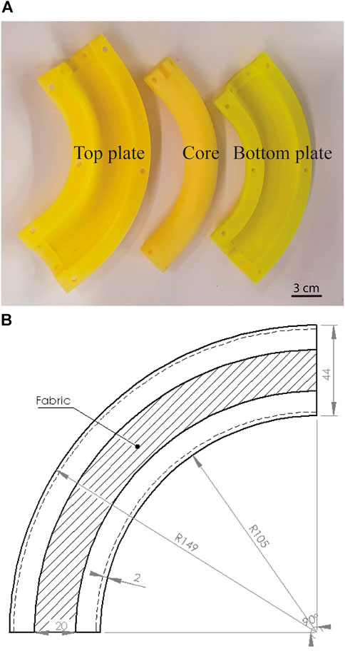
FIGURE 2. The Mold (A) and the dimension of a fabricated actuator (B).
3.3 Performance variation testing
Ten identical soft actuator chambers were fabricated using the process described in Section 3.2. The set of chambers produced is shown in Figure 1E. Each soft actuator was installed into a mount and apparatus consisting of a hose barb connected to an air supply valve, and seven Polhemus Liberty (Colchester, VT, United States) motion sensors were installed at key locations. These sensors returned the Cartesian X, Y, and Z coordinates, as well as the Euler angles of each sensor. The sampling rate of these sensors was set to 38 Hz.
The pressure within the chamber was controlled at each instant in time using a proportional valve (Enfield LS-V25S). The valve spool was driven by a motor driver shield (Pololu A4990), which received PWM signals from an Arduino microcontroller board running custom firmware for the test. The firmware caused the chamber to inflate and deflate up to 640 cycles for the first six actuators and 1,280 cycles for the last four. In each cycle, the chamber’s pressure was controlled to rise from 6.894 kPa (1 psi) to 20.684 kPa (3 psi), and then return to 6.894 kPa over a period of 45 s. The chamber pressure was measured by a pressure sensor (HoneyWell SSCSANN001BGAA5).
Throughout the experiment, a Python script pulled position data directly from the Polhemus sensors via an RS232 cable every 10 min for 45-s intervals. The Python script had an auto-save function to prevent data loss in case of any errors. At the end of the experiment, two files were generated: one file containing the position data for every sensor, and another file containing the timestamps of each measurement.
To check for leakage, the bubbling method was used before each experiment. In the future, we may also use the method described in (Shi et al., 2022) to evaluate leakage during testing processes.
3.4 Burst testing
Following the life test, for those actuators that withstood the maximum number of cycles without breakage, we conducted a burst test to determine the chamber pressure each actuator could withstand. This test was used to evaluate the level of uniformity from chamber to chamber at which material failure would occur. In the burst experiment, we inflated each actuator slowly at 0.31 kPa/s until it broke. The process was repeated for all ten actuators. The history of the pressurized process was recorded and analyzed to define the failure zone and failure method for this type of soft actuator.
3.5 Material testing
Following the burst test, we evaluated the material properties of the elastomer matrix that made up the chamber of the actuator. Material properties of the elastomer under tensile loading were evaluated using a dogbone tensile specimen cut from the soft actuators that had experienced material failure in the burst test. A custom-built tensile test frame with a 50 N load cell, shown in Figure 3, was used to perform the testing. Pneumatic grips were used during testing to prevent slippage of the test specimens at high strains. Elastomers exhibit large deformation under uniaxial tension, so true strain must be captured using a 3-D image correlation system. In our set up, full-field strain measurements were performed using a commercially available (Correlated Solutions) Digital Image Correlation (DIC). DIC requires a monodisperse, high contrast, speckle pattern to be applied to the material. Specimens were prepared by spraying white spray paint on the surface of the specimen and a coat of black paint along the back gauge length for higher contrast. The load frame was controlled using custom control software developed in LabView (National Instruments).
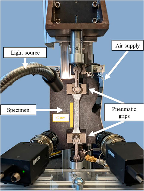
FIGURE 3. Cyclic fatigue set up for digital image correlation with specimen loaded into the pneumatic grips.
4 Experimental results
We analyzed the position data collected from the motion tracker sensor placed at the tips of ten actuators to study the motion over long periods of operation and to determine whether the motion profile varied due to repeated strains in the material. We also analyzed the pressure data from the burst tests to understand the failure behavior of the soft actuators. In addition, the strain-stress data from the tensile tests was analyzed to evaluate the material properties after several hundred strain cycles.
4.1 Performance variation
4.1.1 Elevation variation
Figure 4 shows the motion history of nine soft actuators (actuator 4, which failed after only a few hundred cycles, is excluded). Each subfigure includes five inflation curves showing the path of the tip, each curve shown in a different color, plotted in the three-dimensional space in which the actuator moves (base frame of the actuator). The curves shown are the trajectories of the second cycle, a cycle at 25% of life, 50% of life, 75% of life, and the final cycle of the whole life testing process. The reason the second cycle is shown (rather than the first curve) for the comparison is that there were considerable deviations from the first cycle to the subsequent ones due to the “fading memory” material phenomenon Nakajima et al. (2014), which will be described more carefully later in this section. The spatial unit was measured in mm. Since each actuator could not be installed on the hose barb precisely the same as each of the others relative to the station of the motion tracker system, each 3D subfigure is shown with a different view vector to have the best illustration of its performance. It is evident from the plots that the trajectories of each actuator vary over the course of many cycles, both in the shape of the trajectory and the extents of the motion. Furthermore, how much each trajectory varies from the starting trajectory varies from actuator to actuator. The gaps between the initial and later curves are most visible in actuator 1 while they just nearly overlap with one another in actuator 9. Most of the actuators (actuator 1, 2, 4, 5, 6, 8, 10) show an increase in the Z coordinate of the curves at later life, while the trajectories of actuator 3 and 7 tended to shift only horizontally. The increased elevation of the tip is likely due to degradation in the elasticity of the material that leads to greater strains for the same inflation pressure to counteract the gravity force acting on the actuator tips. Note that our soft actuators may have slight variations in the fabrication processes due to random locations of air bubbles (if they exist), or the variation in the alignment of the fabrics along actuators’ bodies. Therefore, we seek the trends in the movement of this type of pneumatic fabric-reinforced soft actuator through the most common behaviors of all the tested actuators.
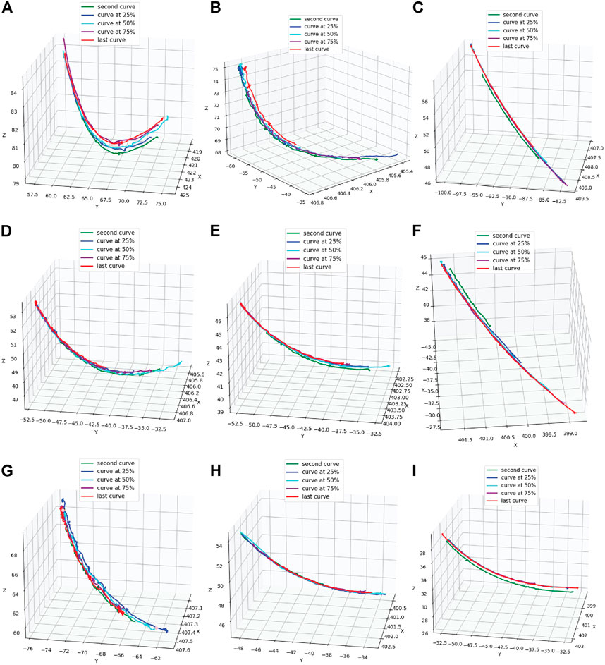
FIGURE 4. The trajectories of the tips of the tested actuators over time, (A) actuator 1, (B)actuator 2, (C) actuator 3, (D) actuator 5, (E) actuator 6, (F) actuator 7, (G) actuator 8, (H) actuator 9, (I) actuator 10.
4.1.2 Trajectory deviation
One noteworthy observation is the deviation between the trajectories of the tip over the life of the soft actuator. We measured the deviations as the average distances between the initial inflation curve (the second cycle recorded) and the remaining curves shown in Figure 4. The deviations are summarized in the chart shown in Figure 5. The distances gradually increase in the case of actuator 1, 6, and 8. For the other cases, the deviations may be closer or further away from the initial curve at various stages of life but still show variation over the course of testing.
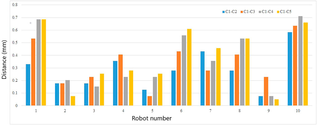
FIGURE 5. The average distance from curve 1 (at the beginning of life) to the other curves. C1-C2: Distance between the curve at beginning and the curve at 25% of life; C1-C3: Distance between the curve at beginning and the curve at 50% of life; C1-C4: Distance between the curve at beginning and the curve at 75% of life; C1-C5: Distance between the curve at beginning and the curve at 100% of life.
In most cases (actuator 1, 3, 5, 6, 7, 8, and 10), the distances between the first curve (at the beginning of life) and the fifth curve (100% of life) (yellow bars) are bigger than those between the first and the second curve (at 25% of life) (blue bars). This indicates that the trajectory of the soft actuators will shift over time, and the deviation tends to grow for longer operation duration. We also observed that actuator 4 stopped moving after about 75% of the experiment time due to leakage.
4.1.3 Fading memory
As mentioned in the previous section, the first cycle of each soft actuator was notably different from the subsequent cycles. This behavior was observed whenever the actuators started to move after being held at a static state. As shown in Figure 6, the tip motion in the first cycle had lower amplitude and shorter excursion compared to the following cycles. This phenomenon is known as “fading memory” as described by Nakajima et al. (2014). This property allows the host material to retain the effects of a recent input sequence within the system, allowing for the integration of stimulus information over time. This is similar to the rise time of a dynamic system. When the soft body has received sufficient actuation stimulus, the actuator will leave the transient region and enter a more stable state.
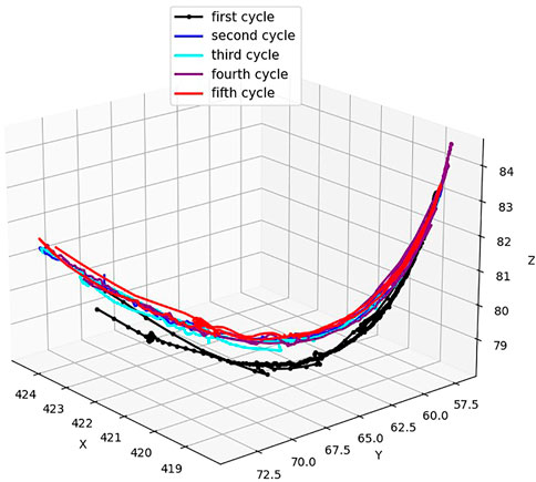
FIGURE 6. Actuator excursions during the inflation motion from Cycle 1 when the actuator starts operation and the following cycles (actuator 1).
4.1.4 Trajectory’s length variation
We also examined the variation in arc lengths of the trajectories during inflation. The chart in Figure 7 summarizes the arc lengths for all ten actuators, with the mean length of the trajectory being 16.94 mm and a standard deviation of 5.33 mm across all actuators. There is a common trend for the actuators (with the exception of actuator 10) in which the excursion on the second cycle (represented by the second bars in the chart) is always longer than the first curve (the first bars in the chart). For the lengths of curves 3, 4, and 5, no consistent trend was observed from actuator to actuator. This data shows a rule in the variation of the actuators’ performance where the actuators tend to increase their path lengths in the working range prior to 160 cycles. This is because, in this zone, the elasticity of the silicone is decreasing. When the actuators operate longer than this threshold, the actuators reach a steady state in elasticity (fully actuated), and there is no variation trend in this range. This result supports the finding in the work of Yap et al. (2016b), where their 3D-printed soft actuator with planar motions was fully actuated after undergoing 300 cycles at 250 kPa.
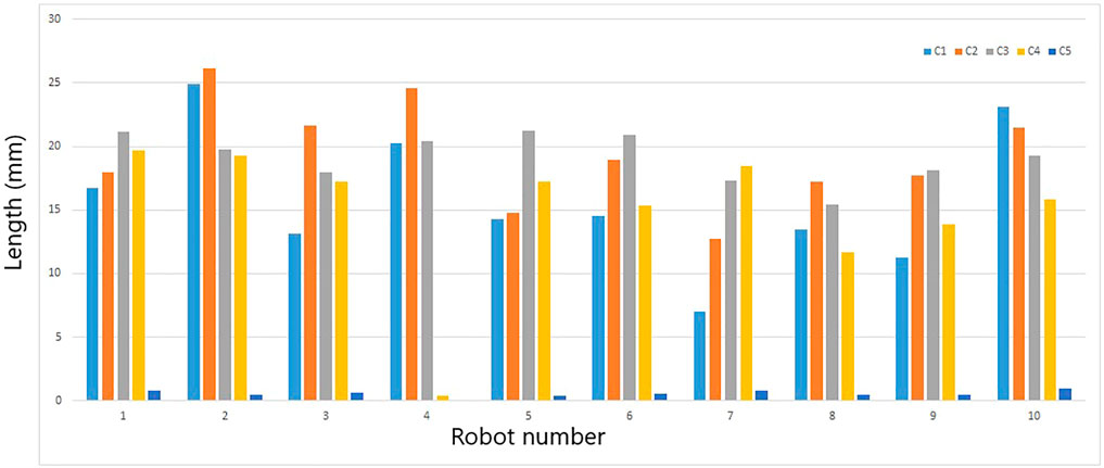
FIGURE 7. The lengths of five inflation curves of each actuator. C1: the curve at beginning of life; C2: the curve at 25% of life; C3: the curve at 50% of life; C4: the curve at 75% of life; C5: the curve at 100% of life.
4.1.5 Hysteresis variation
Another interesting behavior of the soft actuators is hysteresis. Hysteresis is defined as a “special type of memory-based relation between the input and the output” (Macki et al., 1993) or a “rate-independent memory effect” (Polygerinos et al., 2015b). Generally, hysteresis is used to describe a dynamical system with a phase lag that depends on the input (Bui and Schultz, 2021). For our soft actuator, its tip trajectory is described as a hysteresis loop where the tip follows different curves depending on whether the chamber is increasing or decreasing. This idea is illustrated more clearly in Figure 8, where the first cycle of actuator 2 is divided into segments, the inflation curve (red) and the deflation curve (blue). In the same experiment, we also recorded the hysteresis loops exhibited by each of the ten actuators at the cycles mentioned in Section 3.1.1 (beginning, 25%, 50%, 75%, and 100% of life).
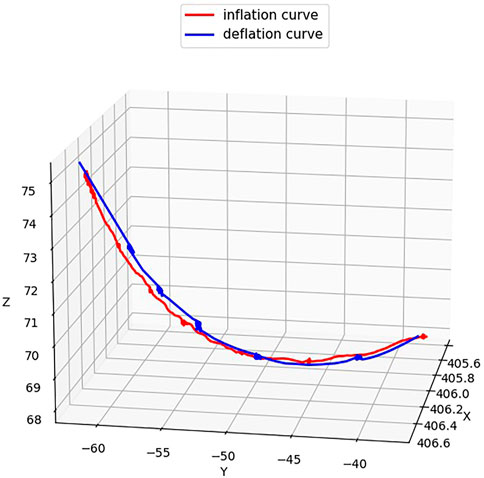
FIGURE 8. The hysteresis motion of actuator 2 shows the difference between inflation and deflation curves.
We investigated whether the hysteresis varied over the course of the actuator’s life by examining the variation in the width of the hysteresis loops. We calculated the average distances between the inflation and deflation curves of each cycle, and the results are summarized in Figure 9. The examination of hysteresis over the course of each actuator’s life showed that the hysteresis properties did change slightly over the course of the actuator’s life. For most of the actuators (actuator 1, 5, 7, 8, 9, and 10), the hysteresis distances in the second hysteresis curve (the cycle at 25% of the process) were longer than those of the first one. This result is consistent with the result about the curve’s length in the previous part, where the elasticity was decreasing when the actuators were working in the range less than 160 cycles. Beyond this range, the hysteresis varied in a manner that was inconsistent from actuator to actuator and did not exhibit a particular pattern. The average distance observed from the inflation to the deflation curve was 4.31 mm, which is equal to 1% of the average trajectory length of all the actuators.
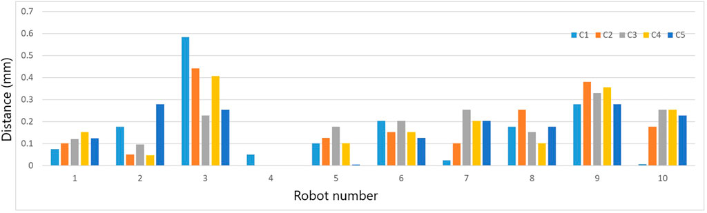
FIGURE 9. The average distances between inflation and deflation curves in each cycle of each actuator. C1: Hysteresis at beginning of life; C2: Hysteresis at 25% of life; C3: Hysteresis at 50% of life; C4: Hysteresis at 75% of life; C5: Hysteresis at 100% of life.
4.2 Burst testing
The burst test broke the actuators and the tears in the broken ones showed different patterns. Some of the tears that occurred are shown in Figure 10A. It can be seen that while the tears are at different locations, they tend to be longitudinal. This may be due to the grooves on the 3D-printed mold surface.
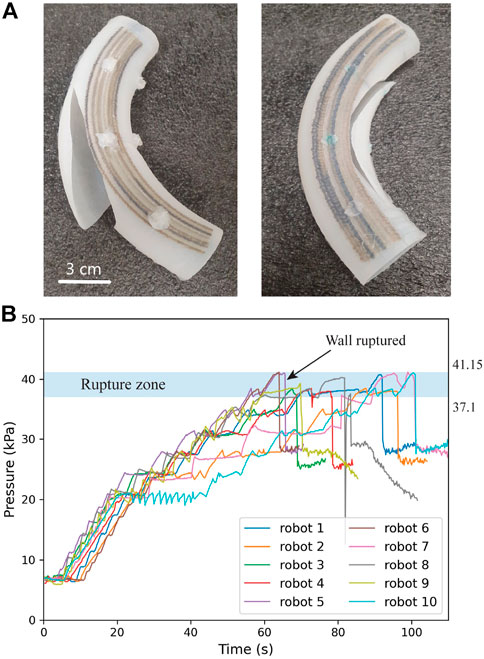
FIGURE 10. The rupture of ten actuators, (A) The photos of broken robots, (B) The rupture zone of tested samples. Each curve corresponds to the burst test history of a actuator. The point where pressure dropped abruptly is where fracture happened.
Figure 10B shows the result from the burst tests. The result reveals that the rupture zone of the tested actuators is from 37.1 to 41.15 kPa. Actuator 6 withstood the maximum pressure up to 41.15 kPa while actuator 4 ruptured earliest at 37.1 kPa. The rupture zone spans a 4.05 kPa range, which is less than 10% of the burst pressure of the strongest soft actuator. This indicates that it is consistent from actuator to actuator out of the same fabrication process. The burst test of actuator 4 confirmed the presence of a defect within this actuator seen in the life tests where the actuator stopped moving prior to the designated number of cycles. This experiment provides us with information about the burst pressure of this actuator design. Based on this information, we can determine the safe range of pressures for operation.
4.3 Cyclic tensile testing
In addition to observing the motion hysteresis exhibited by the soft robot over the course of its motion, the robot wall material was evaluated in cyclic fatigue to assess the effect of cycling and strain rate. In these experiments tensile specimens cut from a robot were subjected to cyclic fatigue for 10 cycles at displacement rates from 1 mm/s to 10 mm/s. The stress-strain traces shown in Figure 11 display the tensile behavior of a dogbone sample taken from robot number 5. Each cycle is plotted atop the previous one with the red-green color gradient representing the number of cycles. We can see that the first cycle (red) has slightly higher peak stresses than the last cycle (green). It is evident from the curves in Figure 11 that the amount of hysteresis varies depending on loading rate. As the loading rate increases, all material specimens exhibit increasing hysteresis.
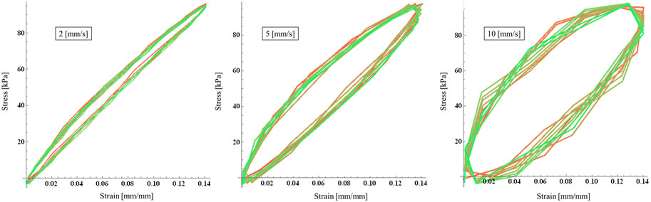
FIGURE 11. Stress strain curves for robot number 5 at 2, 5, and 10 mm/s. The red-green gradient indicates the cycle count: first cycle is red; last cycle, green.
In Figure 11, we observed a slight shift downward from cycle to cycle for each graph. The decrease in stress observed in each subsequent cycle indicates that the material is undergoing stress softening, the consequence of which is residual strain or permanent set (Diani et al., 2009). Stress softening occurs during cyclic loading and unloading in elastomeric material and can be seen increasing with the increasing strain rate in the growing envelopes in Figure 11. The cyclical behavior of the soft robot material is critical to the operation and lifespan of the robot. While not permanent, the stress softening behavior must be taken into account in modeling and control of the inflation-displacement relationship as the same inflation pressure will lead to increased deformation of the robot walls as inflation cycles increase.
5 Conclusion
In this study, we conducted endurance experiments on ten pneumatic fabric-reinforced soft actuators and observed the variation in the inflation-displacement relationship from cycle to cycle. The experiments included the motion variation test, the burst test, and the tensile test of the chamber wall material. The experimental results showed that the trajectories traced out by the actuator’s tip shift over the course of the actuator’s life, and this deviation from the trajectory of the earliest cycle increases over the first several hundred cycles of the actuator’s life. The experiments also revealed that break-in effects and hysteresis have a substantial effect on the motion that the actuator generates upon inflation. The lengths of the motion paths and the widths of hysteresis loops also increase prior to the actuators reaching 160 cycles, after which the material can reliably be considered fully actuated. Life tests also showed that this type of actuator can perform more than 1,280 cycles without breaking.
It is important to note that the first cycle from a static state will be considerably different from the ones that follow because the material has fading memory. We conclude that the break-in, hysteresis, and ageing effects cause the displacement of the robot to depend on the operational history of the robot and not only on variations in material or manufacturing effects, which could potentially be characterized prior to putting the robot into service. The results described in this paper underscore the importance of integrating position or configuration sensors into the body of the robot. From such sensors, the spatial location of the robot can be measured or observed directly, and the pressure can be adjusted in closed-loop fashion until the desired position is reached. Even if closed-loop control is used, the tests conducted in this paper are still relevant to accurate positioning. To guarantee the reliability of the soft actuators in their applications, we need to account for these variations, as well as their limits and uncertainties, in the design of the controller. Incorporating these limits observed into the controller can be used to ensure controller stability and adequate speed of response as the pressure-displacement behavior changes during operation.
The limitation of the current work is that it does not provide a systematic relationship between the measured quantities (e.g., between path-length variation and hysteresis variation). Incorporating all the variations can be challenging for the controller design. However, with the development of new machine learning algorithms, we believe that the data collected from this work can be trained and usefully applied for the future robust controller. In future work, we will design a robust controller that compensates for the uncertainties estimated in real-time to precisely position this soft actuator. Given knowledge of how the robot is operating (e.g., whether it is the first cycle after a long static period or the age of the robot), the control algorithm will adjust adaptive parameters to incorporate this knowledge into the controller. This will be important in enabling inflatable soft robots composed of fabric-reinforced elastomers to reliably complete tasks.
Data availability statement
The raw data supporting the conclusion of this article will be made available by the authors, without undue reservation.
Author contributions
In this work, PB proposed the research approach and did the simulation. The fabrication and measurement were set up and done by BP and AP. The tensile tests were done by CS and MK. JS provided methodology and made important revisions to the paper. All authors contributed to the article and approved the submitted version.
Funding
This work is supported by NSF EFRI grant No. 1935312, “C3 SoRo: Between a Soft actuator and a Hard Place: Estimation and Control Algorithms that Exploit Soft actuators’ Unique Abilities” and NSF EPSCOR REU 2022 grant No. OIA-1946093, “Development of New Sensing Approaches for a Fabric-Reinforced Soft actuator”.
Acknowledgments
We thank J. Garrett Williamson for his support in preparing the facilities to fabricate the actuators.
Conflict of interest
The authors declare that the research was conducted in the absence of any commercial or financial relationships that could be construed as a potential conflict of interest.
Publisher’s note
All claims expressed in this article are solely those of the authors and do not necessarily represent those of their affiliated organizations, or those of the publisher, the editors and the reviewers. Any product that may be evaluated in this article, or claim that may be made by its manufacturer, is not guaranteed or endorsed by the publisher.
References
Amend, J., Cheng, N., Fakhouri, S., and Culley, B. (2016). Soft robotics commercialization: Jamming grippers from research to product. Soft Robot.3 (4), 213–222. doi:10.1089/soro.2016.0021
Bar-Cohen, Y. (2001). Electroactive polymer (EAP) actuators as artificial muscles: Reality, potential, and challenges. Washington: SPIE Press.
Bui, P. D. H., and Schultz, J. (2021). A semilinear parameter-Varying observer method for fabric reinforced soft robots. Front. Robot. AI8, 749591. doi:10.3389/frobt.2021.749591
Connolly, F., Walsh, C. J., and Bertoldi, K. (2017). Automatic design of fiber-reinforced soft actuators for trajectory matching. PNAS14 (1), 51–56. doi:10.1073/pnas.1615140114
[Dataset] Diani, J., Fayolle, B., and Gilormini, P. (2009). A review on the mullins effect. Eur. Polym. J.45 (3), 601–612. doi:10.1016/j.eurpolymj.2008.11.017
Durante, F., Antonelli, M. G., Zobel, P. B., and Raparelli, T. (2021). A procedure for the fatigue life prediction of straight fibers pneumatic muscles. Actuators10 (300), 1–13. doi:10.3390/act10110300
Galloway, K. C., Polygerinos, P., Walsh, C. J., and Wood, R. J. (2013). “Mechanically programmable bend radius for fiber-reinforced soft actuators,” in 2013 16th International Conference on Advanced Robotics (ICAR), Montevideo, Uruguay, 25-29 November 2013, 1–6. doi:10.1109/ICAR.2013.6766586
Ilievski, F., Mazzeo, A., Shepherd, R., Chen, X., and Whitesides, G. (2011). Soft robotics for chemists. Angew. Chem. Int. Ed.50, 1890–1895. doi:10.1002/anie.201006464
Jeong, U., Kim, K., Kim, S.-H., Choi, H., Youn, B. D., and Cho, K.-J. (2021). Reliability analysis of a tendon-driven actuation for soft robots. Int. J. Robot. Res.40 (1), 494–511. doi:10.1177/0278364920907151
Kingsley, D., and Quinn, R. (2002). “Fatigue life and frequency response of braided pneumatic actuators,” in IEEE International Conference on Robotics and Automation (ICRA), Washington, DC, USA, 11-15 May 2002, 2830–2835. doi:10.1109/ROBOT.2002.1013661
Klute, G., and Hannaford, B. (1998). “Fatigue characteristics of McKibben artificial muscle actuators,” in Proceedings of the 1998 JEEERSJ Intl. Conference on Intelligent Robots and Systems, Victoria, B.C., Canada, 17-17 October 1998, 1776–1781. doi:10.1109/IROS.1998.724854
Lee, J. A., Li, N., Haines, C. S., Kim, K. J., Lepró, X., Ovalle-Robles, R., et al. (2017). Electrochemically powered, energy-conserving carbon nanotube artificial muscles. Adv. Mat.29 (31), 1700870. doi:10.1002/adma.201700870
Macki, J. W., Nistri, P., and Zecca, P. (1993). Mathematical models for hysteresis. SIAM Rev.35 (1), 94–123. doi:10.1137/1035005
Manti, M., Hassan, T., Passetti, G., D’Elia, N., Laschi, C., and Cianchetti, M. (2015). A bioinspired soft robotic gripper for adaptable and effective grasping. Soft Robot.2, 107–116. doi:10.1089/soro.2015.0009
Miron, G., Bédard, B., and Plante, J.-S. (2018). Sleeved bending actuators for soft grippers: A durable solution for high force-to-weight applications. Actuators7 (40), 40–16. doi:10.3390/act7030040
Miron, G., and Plante, J.-S. (2016). Design principles for improved fatigue life of high-strain pneumatic artificial muscles. Soft Robot.3 (4), 177–185. doi:10.1089/soro.2016.0011
Mosadegh, B., Polygerinos, P., Keplinger, C., Wennstedt, S. W., Shepherd, R., Gupta, U., et al. (2014). Pneumatic networks for soft robotics that actuate rapidly. Adv. Funct. Mat.24 (15), 2163–2170. doi:10.1002/adfm.201303288
Nakajima, K., Li, T., Hauser, H., and Pfeifer, R. (2014). Exploiting short-term memory in soft body dynamics as a computational resource. J. R. Soc. Interface11, 20140437. doi:10.1098/rsif.2014.0437
Park, Y., Chen, B., Pérez-Arancibia, N., Young, D., Stirling, L., Wood, R., et al. (2014). Design and control of a bio-inspired soft wearable robotic device for ankle-foot rehabilitation. Bioinspir Biomim.9, 016007. doi:10.1088/1748-3182/9/1/016007
Polygerinos, P., Wang, Z., Galloway, K., Wood, R., and Walsh, C. (2015a). Soft robotic glove for combined assistance and at-home rehabilitation. Rob. Auton. Syst.73, 135–143. doi:10.1016/j.robot.2014.08.014
Polygerinos, P., Wang, Z., Overvelde, J. T. B., Galloway, K. C., Wood, R. J., Bertoldi, K., et al. (2015b). Modeling of soft fiber-reinforced bending actuators. IEEE Trans. Robot.31 (3), 778–789. doi:10.1109/TRO.2015.2428504
Rosset, S., and Shea, H. R. (2012). Flexible and stretchable electrodes for dielectric elastomer actuators. Appl. Phys. A110, 281–307. doi:10.1007/s00339-012-7402-8
Shi, Y., Chang, J., Wang, Y., Zhao, X., Zhang, Q., and Yang, L. (2022). Gas leakage detection and pressure difference identification by asymmetric differential pressure method. Chin. J. Mech. Eng.35, 44. doi:10.1186/s10033-022-00697-1
Singh, G., and Krishnan, G. (2015). “An isoperimetric formulation to predict deformation behavior of pneumatic fiber reinforced elastomeric actuators,” in 2015 IEEE/RSJ International Conference on Intelligent Robots and Systems (IROS), Hamburg, Germany, 28 September 2015 - 02 October 2015, 1738–1743. doi:10.1109/IROS.2015.7353602
Su, H., Hou, X., Zhang, X., Qi, W., Cai, S., Xiong, X., et al. (2022). Pneumatic soft robots: Challenges and benefits. Actuators11, 92. doi:10.3390/act11030092
Takayama, T., Takeshima, H., Hori, T., and Omata, T. (2015). A twisted bundled tube locomotive device proposed for in-pipe mobile robot. IEEE/ASME Trans. Mechatron.20, 2915–2923. doi:10.1109/TMECH.2015.2411752
Wallace, G., Teasdale, P., Spinks, G., and Kane-Maguire, L. (2008). Conductive electroactive polymers: Intelligent polymer systems. Florida: CRC Press.
Wang, M., Cheng, Z.-W., Zuo, B., Chen, X.-M., Huang, S., and Yang, H. (2020). Liquid crystal elastomer electric locomotives. ACS Macro Lett.9 (6), 860–865. doi:10.1021/acsmacrolett.0c00333
Wang, Z., Torigoe, Y., and Hirai, S. (2017). A prestressed soft gripper: Design, modeling, fabrication, and tests for food handling. IEEE Robot. Autom. Lett.2 (4), 1909–1916. doi:10.1109/LRA.2017.2714141
Williamson, J. G., Schell, C., Keller, M., and Schultz, J. (2021). “Extending the reach of single-chamber inflatable soft robots using Magnetorheological Fluids,” in IEEE International Conference on Soft Robotics (RoboSoft), New Haven, Connecticut, 12-16 April 2021, 119–125. doi:10.1109/RoboSoft51838.2021.9479295
Woods, B. K., Gentry, M. F., Kothera, C. S., and Wereley, N. M. (2011). Fatigue life testing of swaged pneumatic artificial muscles as actuators for aerospace applications. J. Intell. Mat. Syst. Struct.23 (3), 327–343. doi:10.1177/1045389X11433495
Xu, L., Xue, F., Zheng, H., Ji, Q., Qiu, C., Chen, Z., et al. (2022). An insect larvae inspired MXene-based jumping actuator with controllable motion powered by light. Nano Energy103 (2022), 107848. doi:10.1016/j.nanoen.2022.107848
Yap, H. K., Lim, J., Nasrallah, F., Goh, J., and Yeow, C. (2016a). Characterisation and evaluation of soft elastomeric actuators for hand assistive and rehabilitation applications. J. Med. Eng. Technol.40, 199–209. doi:10.3109/03091902.2016.1161853
Yap, H. K., Ng, H. Y., and Yeow, C.-H. (2016b). High-force soft printable pneumatics for soft robotic applications. Soft Robot.3 (3), 144–158. doi:10.1089/soro.2016.0030
Keywords: pneumatic soft actuators, fabric-reinforced, hysteresis, fatigue life testing, silicone, performance variation, repeatability
Citation: Bui PDH, Prugh B, Padilla AME, Schell C, Keller M and Schultz JA (2023) Endurance tests for a fabric_reinforced inflatable soft actuator. Front. Mater. 10:1112540. doi: 10.3389/fmats.2023.1112540
Received: 30 November 2022; Accepted: 15 May 2023;
Published: 25 May 2023.
Edited by:
Ying Hu, Hefei University of Technology, ChinaReviewed by:
Hang Su, Polytechnic University of Milan, ItalyLiangliang Xu, Harbin Institute of Technology, China
Copyright © 2023 Bui, Prugh, Padilla, Schell, Keller and Schultz. This is an open-access article distributed under the terms of the Creative Commons Attribution License (CC BY). The use, distribution or reproduction in other forums is permitted, provided the original author(s) and the copyright owner(s) are credited and that the original publication in this journal is cited, in accordance with accepted academic practice. No use, distribution or reproduction is permitted which does not comply with these terms.
*Correspondence: Phuc D. H. Bui, phuc-bui@utulsa.edu