Effects of laser energy density on morphology features and microstructures of the single molten track in selective laser melting
 Sen Wang1,2,3
  Runqi Yang
 Jing Li
- 1University of Chinese Academy of Sciences, Chongqing, China
- 2Chongqing Institute of Green and Intelligent Technology, Chinese Academy of Sciences, Chongqing, China
- 3Key Laboratory of Additive Manufacturing Technology and System, Chongqing, China
Single molten track (SMT) is the basic unit of the selective laser melting (SLM) process, of which the morphology features and microstructures have great significance on the molding quality. In this study, the effects of laser energy density (LED) on characteristics of SMT were studied with 316 L stainless steel processing by SLM. The results indicate that an optimized range of LED was between 200 and 500 J/mm3, which was the best for SLM process of 316 L leading to beautiful SMT appearance such as continuous uniform water-ridge-like surface, good contour straightness, smooth edges, little adhesive powder, and high densification. The microstructures of the SMT molten pool are mainly composed of equiaxed cellular and columnar dendrites. As the LED decreased, the cellular became smaller and disappeared, while the length and width of columnar crystals even gradually increased. The size of the cellular varies between 0.43 and 1.70 μm with the LEDs increase. The relationship between SMT characteristics and LED found in this work can be readily used to optimize SMT and control the microstructures in situ, and the laser energy density range that the work has identified will simplify most of the guess work in additive manufacturing.
1 Introduction
Selective laser melting (SLM) is one or multi-laser beams that move along a pre-planned path to melt the metal powder with a particle size distribution of 15–50 μm, track by track to form a layer and then form it into a part layer by layer (Frazier, 2014; DebRoy et al., 2018; Ngo et al., 2018). Forming accuracy, density, and microstructures are key issues of the technology (Yan et al., 2017). As the basic unit of SLM-process, the evolution of morphology features and microstructures of the single molten track (SMT) is the basis for the above issues (Aversa et al., 2018). This is because the morphology features and microstructures of the SMT are influenced by the laser energy density (LED), material properties, and powder distribution. Numerous studies have investigated the effect of laser parameters on SMT characteristics.
A large number of articles have studied the relationship between morphology and size evolution laws of SMT with laser power and scanning speed. Aboulkhair studied the effect of scanning speed on the formation of SMT and single layer of aluminum alloy, whose width and depth declined with the increase of scanning speed (Aboulkhair et al., 2016). Wei investigated the influence of laser power and scanning speed on the surface morphology of SMT and the densification behavior and found that the porosity rate was dependent on LED and hatch space (Wei et al., 2017a). Sun also studied the effect of SMT and hatch space on density through the theoretical derivation and experiment, and indicated that the build rate could be enhanced by about 72% with a 380 W laser (Sun et al., 2016). Guo designed a series of experiments for SMT and single layers under different process parameters (laser power, scanning speed, and hatch space) to evaluate the SLM process for Nb-37Ti-13Cr-2Al-1Si (at%) alloy, whose width and penetration depth of SMT increased with an increase of LED (Guo et al., 2018). Yadroitsev has also studied the effect of process parameters on SMT and the surface quality with several powders, including SS grade 316 L, CuNi10, tool steel H13, and Inconel 625. They found a negative correlation between thermal conductivity and optimal scanning speed for continuous SMT. They also found that the contact angle of the molten pool tended to decrease with increasing laser power. The simulation was in agreement with experimental results to determine the optimal conditions for desired microstructures and mechanical properties (Yadroitsev et al., 2010; Yadroitsev and Smurov, 2010; Yadroitsev et al., 2015). Li developed a process map for SLM of Ni625 alloy, changing the laser power and scanning speed over a wide range, and presented that SMT height, surface roughness, and contact angle were independent of scanning speed. This appears to be different from the results of others and needs to be verified (Li et al., 2017). Shi investigated the influence of laser parameters on the molten pool characteristics of TiAl by linear regression analysis. They pointed out that an inappropriate combination of process parameters can lead to evaporation and instability of the molten pool, which in turn causes cracking, balling and reduces the linear correlation (Shi et al., 2017). Wei also studied the geometrical properties of the molten pool of TiAl alloy at 325 W and 200–2200 mm/s and obtained dense parts with good mechanical properties based on SMT (Wei et al., 2017b). Darvish indicated that the size and shape of SMT were the predominant factors related to the amount of lack of fusion (LOF) during CoCrMo alloy in the SLM-process. They concluded that there was a rapid decay in the amount of LOF as laser power increases from 180 W to 220 W, which is due to the geometric effect of the track size on the overlapping coverage (Darvish et al., 2016). King studied the relationship between SMT depth and the conduction of heat during SLM-process, and found that the keyhole was formed as energy input to the molten pool increased, whereas the depth of the molten pool was controlled by the evaporation of the metal (King et al., 2014). This was consistent with the results of Madison (Madison and Aagesen, 2012) and Rai (Rai et al., 2004), who claimed that thermophysical properties affected the penetration and shape of the molten pool. Khairallah reported that the recoil pressure caused by the evaporation of metal exerts forces on the surface of molten pool and produces surface depression, which contribu tes to the increase in the depth of molten pool (KhairallahAndersonRubenchikKing, 2016).
Numerical simulation was introduced to further analyze SMT characteristics in the SLM-process. A high-fidelity powder-scale model was developed to predict the detailed formation process of single/multiple-track defects, including balling, uniformity, and inter-track voids. Yan developed a powder-scale model to predict the detailed formation of SMT/multiple-track defects. Their simulation results showed that the hatch space should not be larger than the width of the remelted region within the substrate (Yan et al., 2017). Khairallah developed a 3D mesoscopic model to simulate SLM-processes of stainless steel powder under a constant power of 150 W with different scanning speeds. The study displayed that low laser scanning speeds (<750 mm/s) were more suitable to prevent residual pores from forming due to complete melting (Khairallah and Anderson, 2014).
The studies have shown that the characteristics of SMT were affected by scanning speed, hatch space, scanning strategy and LED. The depth and width of SMT decrease as the scanning speed increase, and there is a negative correlation between scanning speed and thermal conductivity of SMT; Hatch space determines the surface morphology and porosity of the SMT; The depth and width of SMT increase as the LED increase, which causes the evaporation of the metal to control the depth and appearance of the molten pool. Most of the studies were focused on density and thermal conductivity, while the study of geometric dimension and microstructures were relatively rare. In this study, the influence of LED on the geometry and microstructures of the molten pool were analyzed in detail, which formed the basis for regulating shape accuracy, density, and microstructures.
2 Material and methods
The metal powder used in this study is 316 L stainless steel with the chemical composition listed in Table 1. The morphology features of the powder is nearly spherical, with smooth and dense surface and good dispersibility, as shown in Figure 1A The particle size distribution of the powder shows a Gaussian distribution with the main particle size range between 10 to 50 μm, which reflects that the powder has good size uniformity, as shown in Figure 1B.

TABLE1. Chemical composition of 316 L powder.
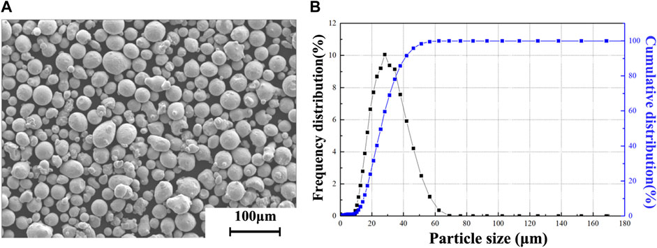
FIGURE 1. (A) SEM morphology, and (B) particle size distribution of 316 L steel powder.
The morphology features and microstructures of SMT under different LEDs were studied. The LED is defined as follows:
where P (W) is the laser power, V (mm/s) is the scanning speed, and D (mm) is the laser beam diameter. The SLM experiment was conducted on a home-made device, and the laser used in this study was a continuous wave IPG fiber laser with a maximum power of 200 W and focal spot size of 60 μm. Laser power from 100 W to 200 W and scanning speed from 100 mm/s to 1000 mm/s were adopted for the experiment, and the corresponding LEDs ranged from 66 J/mm3 to 1019 J/mm3. Layer thickness of 50 μm, single molten track length of 10 mm, and the spacing between tracks of 5 mm were fixed. The SMT cross-section was ground, polished and etched to obtain the structure of molten pool. For clarification, the parameters of the SLM-process are listed in Table 2.
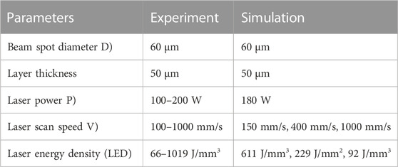
TABLE 2. Parameters for SLM-process.
A multiphase thermal fluid dynamics model of particle melting and solidification was established for the simulation of SLM-process. The model fully considers the events that occurs as the laser beam strikes the surface of a thin powder, such as laser radiation absorption, heat transfer, melting and solidification, fluid flow, evaporation and spattering of materials. A local mesh encryption was conducted for the powders with a uniform mesh size of 2 μm. The beam center was located at a fixed point (x = 0.025 mm, y = 0 mm, z = 0.05 mm) at the initial time, and then moved along x-axis with time lapse. The method and theory of the simulation were described in detail in another paper (Tang et al., 2020).
3 Results and discussion
3.1 Morphology features
Figure 2 shows the morphologies of SMT under different LEDs. As shown in Figure 2A, when LED was less than 100 J/mm3, and the SMT appeared discontinuous because the powder was not sufficiently melted and the liquid phase did not flow sufficiently. Therefore, the concave-convex phenomenon occurred at the edges of the track. When LED was between 100 J/mm3 and 200 J/mm3, the SMT was continuous without obvious water ridges on the surface as shown in Figure 2B. A common feature shared by these two zones was that a large number of pore defects were observed on the surface. This could be related to the gas between powder, which got enclosed by the liquid metal as the laser beam passed by, then escaped from the surface of liquid metal, and finally left pores behind during the solidification of metal since the liquid metal acquired high viscosity when LED was low. When LED was between 200 J/mm3 and 500 J/mm3, the SMT was continuous with evenly water ridges, good contour straightness, smooth edge, little adhesive powder, and high densification, as shown in Figure 2C. This was regarded as the best processing window for 316 L SLM- process. It is worth mentioning that there were almost no pore defects on the track surface, which was related to the high temperature and low viscosity of liquid metal. The pores formed during the gas escapement from the liquid metal can be recovered before the solidification of the liquid metal. When LED was greater than 500 J/mm3, the surface of molten track still showed uniform water ridges, but a lot of splash droplets can be seen around it as shown in Figure 2D. The laser beam with high LED heated the metal to a temperature higher than the boiling point, which led to splash of liquid metal and finally spherical particles around tracks formed. These splashed droplets had high possibility to weld on the surface, which was a drawback for the forming accuracy not only because of the increased surface roughness, but also because of the possible damage to the scraper which led to uneven distribution of raw powder.
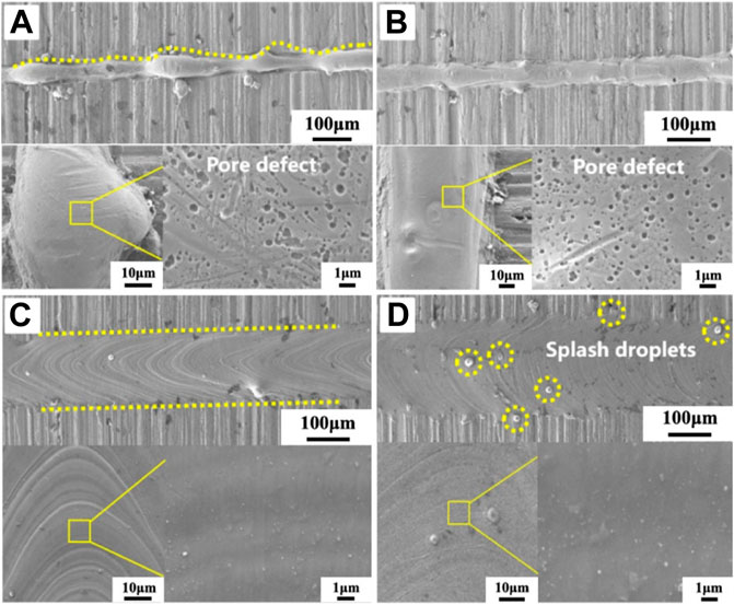
FIGURE 2. Single molten track SEM morphology under LEDs of (A) < 100 J/mm3, (B) 100 J/mm3 ∼ 200 J/mm3, (C) 200 J/mm3 ∼ 500 J/mm3 and (D) 500 J/mm3 ∼1019 J/mm3 with enlarged surface morphology.
The SEM images in Figures 3A–F show that the depth of the molten pool increased sharply and the keyhole phenomenon occurred with LEDs greater than 500 J/mm3. This was mainly due to the high liquid temperature caused by the evaporation phenomenon, which increased the laser absorption in the central region and allowed the heat to transmit further. As shown in Figures 3B, D, hollow pores can be seen in the profile of the molten pool when the LEDs increased to 917 J/mm3 and 1090 J/mm3. This is definitely unacceptable for additive manufacturing, since the appearance of the hollow pores will result in low density and consequently poor mechanical properties. When LEDs were between 100 J/mm3 and 500 J/mm3, there was no keyhole in the molten pool, and the wetting angle of the molten pool was less than 45° as shown in Figures 3G–L, which was conducive to the metallurgical lapping between the tracks. When LED was less than 100 J/mm3, the wetting angle of the molten pool was more than 70°, and there was a tendency for balling as shown in Figures 3K, L. This molten pool was not conducive to the metallurgical lapping between the tracks. It was found that an optimized range of LEDs, e.g., between 200 and 500 J/mm3, was the best for the SLM process of 316 L, which led to the beautiful appearance of single molten track and appropriate molten pool structure based on the result of Figures 2, 3.
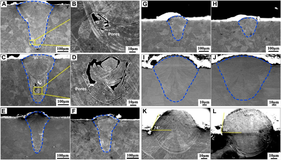
FIGURE 3. SEM morphology of the single molten track cross-section under different laser parameters (A, B) P = 200 W, V = 100 mm/s, LED = 1019 J/mm3 (C, D) P = 180 W, V = 100 mm/s, LED = 917 J/mm3; (E) P = 200 W, V = 200 mm/s, LED = 510 J/mm3; (F) P = 180 W, V = 150 mm/s, LED = 611 J/mm3; (G) P = 200 W, V = 300 mm/s, LED = 340 J/mm3; (H) P = 200 W, V = 400 mm/s, LED = 255 J/mm3; (I) P = 130 W, V = 400 mm/s, LED = 166 J/mm3 (J) P = 160 W, V = 500 mm/s, LED = 163 J/mm3 (K) P = 100 W, V = 700 mm/s, LED = 73 J/mm3 (L) P = 100 W, V = 1000 mm/s, LED = 51 J/mm3.
In order to better understand the phenomena observed in above study and to explore the mechanism, a simulation for the SLM processing was done with different LEDs. As shown in Figure 4A, at a relatively low value of LED, e.g., 92 J/mm3, gasses were traced between the powder and substrate in the liquid metal, which then turned into holes after scanning of laser beam, and the surface of the track was uneven and concave-convex. This was mainly because the insufficient LED resulted in relatively low temperature, high viscosity, and low flow velocity of liquid metal, resulting in the survival of bubbles and poor surface morphology. In some cases, the LED was so small that it was insufficient to penetrate the substrate, and the substrate was even not melted, explaining the concave-convex surface at lower LED. When the LED was set at 229 J/mm3 as shown in Figure 4B, no pores appeared in the molten pool and the surface of the molten track was smooth. This was due to the sufficient LED, which could penetrate into the powder bed. Therefore, a considerable liquid with a larger flow velocity could be formed, which easily migrated towards the edge of the pool and subsequently solidified with a smooth surface. When the LED was 611 J/mm3, the peak temperature of the liquid phase exceeded the vaporization temperature of 316 L. The metal gas increased the absorption of energy, creating a high-temperature-high-pressure region localized under the focus of laser beam, which led to the blowing of both powder and liquid metal, and finally the keyhole formed under the laser beam. Based on the above experimental and simulation results, the following conclusion can be drawn: During the SLM process, a reasonable LED should be selected to avoid the phenomenon of pore defects in the molten pool caused by too low energy and the splashing of the droplets caused by excessive energy.
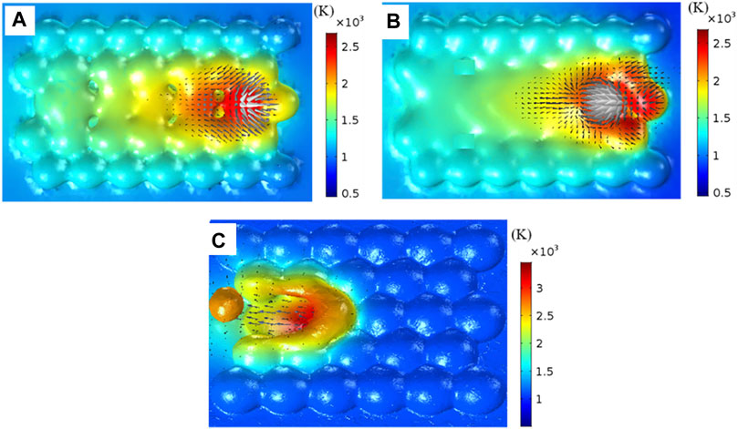
FIGURE 4. The temperature distribution of the molten track under various LED: (A) LED = 92 J/mm3, (B) LED = 229 J/mm3, (C) LED = 611 J/mm3, droplet spatter phenomenon on the top surface under LED = 611 J/mm3.
Effects of LED on the widths and depths of SMT was shown in Figure 5. The Figure 5A shows how the width and depth of SMT are defined. The width of SMT increased from 60 μm to 200 μm with the increase of LED from 66 J/mm3 to 500 J/mm3, and then tended to stabilize at 200 μm even when LED was higher than 500 J/mm3. However, the depth of SMT increased almost linearly from 20 μm to 450 μm when LED was increased from 66 J/mm3 to 1019 J/mm3 without a trend of saturation for LED used in this study. In fact, the width and depth of the melt pool depend on both the laser power and the scanning speed. In the SLM-process, the peak temperature of the material heated by the Gaussian laser heat source is related to the laser power and the scanning speed, as higher laser power or lower scanning speed can increase the peak temperature, and higher peak temperature can lead to a deeper molten pool. Meanwhile, the width of the melt pool is mainly influenced by the scanning speed. It is mainly related to the dwell time of the laser at a fixed point, which increases as the scanning speed decreases; melting the irradiated powder should require a sufficient dwell time, which eventually leads to a wider molten pool. There has a correspondence between laser energy density and scanning speed and laser power:
where P (W) is the laser power, V (mm/s) is the scanning speed, and D (mm) is the laser beam diameter. Therefore, with the increase of LED, the melt pool will be deeper and wider. K is the ratio of depth to width. The K value for each sample is also listed in Figure 5B. As mentioned above, K value increases with increasing LED. From the above studies, the liquid phase involved in the metallurgy of the SMT consisted of two parts, the first part was the solidified body of the previous layer or layers, and the other part was the powder particle of the current layer captured by the laser beam. Since the width of SMT tends to be stable, it is reasonable to assume that the volume of powder captured by the laser beam could have an extreme value for a certain beam diameter. The results can be used to design the hatch space.
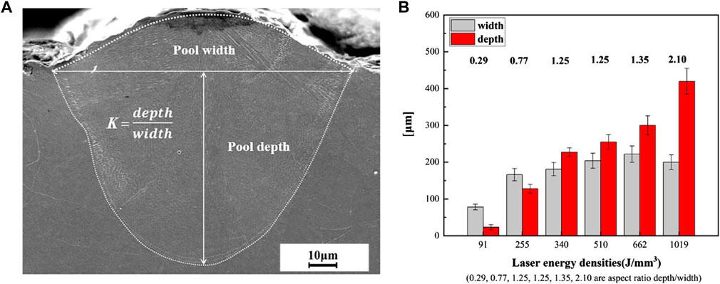
FIGURE 5. (A) The definition of width and depth of SMT, and (B) influence of LEDs on the width and depth of single molten track.
3.2 Microstructure
Figure 6A shows a typical microstructure of 316 L molten pool at a laser power of 100 W and scanning speed of 100 mm/s. It is mainly composed of equiaxed cellulars and columnar dendrites. The magnified microstructure of the different regions of the molten pool boundary is shown in Figures 6B–E, respectively, which were different from one another. However, they all contained columnar dendrites, which were perpendicular to the molten pool boundary. In the central region of the sample, the growth direction of the columnar grains was close to the deposition direction, as shown in Figure 6E. On the other hand, at the edge of the sample, the growth direction of the columnar grains slightly deviated from the deposition direction since the temperature gradient was perpendicular to the molten pool boundary as Figures 6C, D shows. Figure 6B shows that the cellulars were mostly pentagonal in shape and the grain size was small. There were cellulars at the top, center and boundary of the molten pool, which were distributed randomly (Zhang et al., 2018). However, most of the cellulars were located at the top and in the center of the molten pool rather than the boundary.
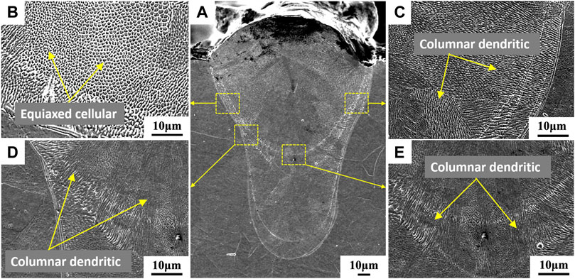
FIGURE 6. (A) Microstructure of 316 L molten pool; (B–E) magnified microstructure of the different regions of the molten pool boundary.
The microstructure was ascribed to the mechanism of heat transfer during SLM. For SMT printing, heat was first transferred across the boundary of the molten pool to the substrate or solidified part, and then dissipated from the substrate, contributing to the direction of crystallization perpendicular to the boundary of the molten pool. This was similar to the solidification process during casting (Zhao et al., 2019). The nucleation near the boundary of the molten pool was inhomogeneous as the solidified part provided the substrate for the epitaxial growth of the subsequent melt, which was the main axis for faster growth. Therefore, grains with crystal orientation perpendicular to the boundary of the molten pool had priority for growth, whereas growth in other directions was inhibited by heat transfer. Parts farther from the boundary of the molten pool were composed of cellular grains because the temperature gradient decreased gradually and so did the solidification rate, leading to the transformation of columnar grains into equiaxed grains and the formation of cellular grains (Ares et al., 2002). This was similar to the transformation of columnar grains into equiaxed grains during casting (Burden and Hunt, 1975). In addition, inside the molten pool, the fast cooling of the melting led to the tension gradient of the surface, which was larger than the viscous force. As a result, the melt became convective and another capillary force known as Marangoni convection, which led to the columnar grains from the boundary to the interior of the molten pool broke into many fine grains near the center of the molten pool (Smith, 1966). Therefore, it indicated that the Marangoni convection contributed to the formation of cellular substructures inside the molten pool.
Figures 7A–C shows the microstructure of the whole molten pool under different LEDs. It showed that under high LED, the columnar and cellular grains appeared alternately, whereas with the decrease of LED, the cellular grains decreased and the columnar grains almost occupied the whole molten pool. Moreover, with the decrease of LED, the columnar grains appeared much thicker. When LED was low, the columnar grains could even grow across the entire molten pool, from the boundary to the top. In addition, as LED decreased, the number of cellulars became smaller and even disappeared, while the length and width of the column crystals gradually increased. This phenomenon may be due to the fact that when LED was low, the temperature gradient decreased, weakening the Marangoni convection phenomenon and allowing the columnar crystals to grow continuously. On the above basis, the size variation of the cellular grains was further studied. Figure 8 shows the cellular grains information at a magnification of 1500 times. It can be seen that with the decrease of LED, the size of cellular tends to decrease, and its shape changes from a pentagon to an ellipse. In Figure 9A, the cellular grains from Figure 8C were extracted using Image-Pro Plus and the average size of all grains was calculated. Figure 9B shows the size distribution of cellular grains ranging from 0.43 to 1.70 μm under different LEDs. The advantage of this study is that it provides a data basis for in situ microstructure regulation of SLM.
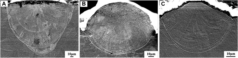
FIGURE 7. The effect of LED on microstructure: (A) P = 160 W, V = 300 mm/s, LED = 272 J/mm3, (B) P = 100 W, V = 200 mm/s, LED = 255 J/mm3, (C) P = 130 W, V = 900 mm/s, LED = 74 J/mm3.
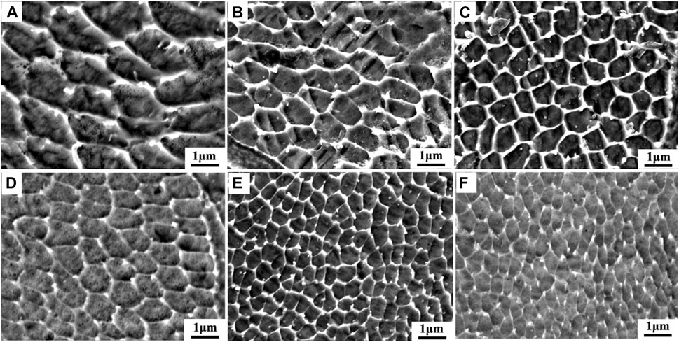
FIGURE 8. The effect of LED on cellular size: (A) P = 180 W, V = 200 mm/s, LED = 459 J/mm3, (B) P = 200 W, V = 300 mm/s, LED = 340 J/mm3, (C) P = 100 W, V = 200 mm/s, LED = 255 J/mm3, (D) P = 160 W, V = 400 mm/s, LED = 204 J/mm3, (E) P = 100 W, V = 400 mm/s, LED = 127 J/mm3, (F) P = 160 W, V = 900 mm/s, LED = 91 J/mm3.
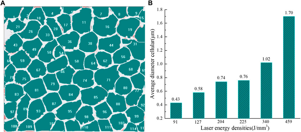
FIGURE 9. (A) The statistical diagram of cellular size under LED of 255 J/mm3 and (B) the average cellular sizes at different LEDs.
4 Conclusion
In this study, the effects of laser energy density on morphology features and microstructures of the single molten track in SLM of 316 L stainless steel powder were studied. The following conclusions have been drawn.
(1) When LED was less than 200 J/mm3, SMT appeared discontinuous and concave-convex, or contained a lot of pore defects on the surface. At LED between 200 J/mm3 and 500 J/mm3, SMT was continuous with evenly water ridges, good contour straightness, smooth edge, little adhesive powder and high densification. For LED greater than 500 J/mm3, many discrete spherical particles adhered to the surface and edge of SMT. The simulation results confirmed that the peak temperature of the molten pool exceeded the material evaporation temperature, which caused droplets to splatter solidify and form spherical particles.
(2) As LED increased, the width of molten pool increased from 60 to 200 μm initially and tended to be stable at 200 μm, the depth linearly increased within a range of 20∼450 μm, and the ratio of depth to width ranged from 0.23 to 2.33.
(3) The microstructure of molten pool is mainly composed of equiaxed cellular and columnar dendrites. In the central region of the molten pool, the growth direction of the columnar grains was close to the deposition direction. In contrast, at the edge of the molten pool, the growth direction of the columnar grains was perpendicular to the molten pool boundary. The cellular grain was mostly pentagon shape and distributed randomly.
(4) As the LED decreased, the number of cellulars became smaller and even disappeared, while length and width of columnar crystals gradually increased. The size distribution of cellular was in the range of 0.43–1.70 μm with increasing value of LED.
Data availability statement
The original contributions presented in the study are included in the article/Supplementary Material, further inquiries can be directed to the corresponding authors.
Author contributions
SW: Data curation, Methodology, Software, Writing original draft. LW: Simulation, Software, Data curation. JQL: Sample treatment, Data curation. RY: Writing—review and editing. JNL: Project administration, Resources, Writing-review and editing. GW: Writing—review and editing, Investigation.
Funding
This work was supported by the Natural Science Foundation Project of Chongqing Science and Technology Commission (Grant No. cstc2020jcyj-msxmX0787), and Binzhou Institute of Technology.
Conflict of interest
The authors declare that the research was conducted in the absence of any commercial or financial relationships that could be construed as a potential conflict of interest.
Publisher’s note
All claims expressed in this article are solely those of the authors and do not necessarily represent those of their affiliated organizations, or those of the publisher, the editors and the reviewers. Any product that may be evaluated in this article, or claim that may be made by its manufacturer, is not guaranteed or endorsed by the publisher.
References
Aboulkhair, N. T., Maskery, I., Tuck, C., Ashcroft, I., and Everitt, N. M. (2016). On the formation of AlSi10Mg single tracks and layers in selective laser melting: Microstructure and nano-mechanical properties. J. Mat. Process. 230, 88–98. doi:10.1016/j.jmatprotec.2015.11.016
Ares, A. E., Caram, R., Rios, C. T., and Schvezov, C. E. (2002). Columnar to equiaxed transition in 316L stainless steel. Fundam. Adv. Mater. energy Convers. 2002, 567–582.
Aversa, A., Moshiri, M., Librera, E., Hadi, M., Marchese, G., Manfredi, D., et al. (2018). Single scan track analyses on aluminium based powders. J. Mat. Process. Tech. 255, 17–25. doi:10.1016/j.jmatprotec.2017.11.055
Burden, M. H., and Hunt, J. D. (1975). A mechanism for the columnar to equiaxed transition in casting or ingots. Metall. Trans. A 6A, 240–241.
Darvish, K., Chen, Z. W., and Pasang, T. (2016). Reducing lack of fusion during selective laser melting of CoCrMo alloy: Effect of laser power on geometrical features of tracks. Mat. Des. 112, 357–366. doi:10.1016/j.matdes.2016.09.086
DebRoy, T., Wei, H. L., Zuback, J. S., Mukherjee, T., Elmer, J. W., Milewski, J. O., et al. (2018). Additive manufacturing of metallic components – process, structure and properties. Prog. Mat. Sci. 92, 112–224. doi:10.1016/j.pmatsci.2017.10.001
Frazier, W. E. (2014). Metal additive manufacturing: A review. J. Mat. Eng. Perform. 23, 1917–1928. doi:10.1007/s11665-014-0958-z
Guo, Y., Jia, L., Kong, B., Wang, N., and Zhang, H. (2018). Single track and single layer formation in selective laser melting of niobium solid solution alloy. Chin. J. Aeronaut. 31, 860–866. doi:10.1016/j.cja.2017.08.019
Khairallah, S. A., Anderson, A. T., Rubenchik, A., and King, W. E. (2016). Laser powder-bed fusion additive manufacturing: Physics of complex melt flow and formation mechanisms of pores, spatter, and denudation zones. Acta Mater 108, 36–45. doi:10.1016/j.actamat.2016.02.014
Khairallah, S. A., and Anderson, A. (2014). Mesoscopic simulation model of selective laser melting of stainless steel powder. J. Mat. Process. Tech. 214, 2627–2636. doi:10.1016/j.jmatprotec.2014.06.001
King, W. E., Barth, H. D., Castillo, V. M., Gallegos, G. F., Gibbs, J. W., Hahn, D. E., et al. (2014). Observation of keyhole-mode laser melting in laser powder-bed fusion additive manufacturing. J. Mat. Process. Tech. 214, 2915–2925. doi:10.1016/j.jmatprotec.2014.06.005
Li, C., Guo, Y. B., and Zhao, J. B. (2017). Interfacial phenomena and characteristics between the deposited material and substrate in selective laser melting Inconel 625. J. Mat. Process. Tech. 243, 269–281. doi:10.1016/j.jmatprotec.2016.12.033
Madison, J. D., and Aagesen, L. K. (2012). Quantitative characterization of porosity in laser welds of stainless steel. Scr. Mater 67, 783–786. doi:10.1016/j.scriptamat.2012.06.015
Ngo, T. D., Kashani, A., Imbalzano, G., Nguyen, K. T. Q., and Hui, D. (2018). Additive manufacturing (3D printing): A review of materials, methods, applications and challenges. Compos. Part B - Eng. 143, 172–196. doi:10.1016/j.compositesb.2018.02.012
Rai, R., Elmer, J. W., Palmer, T. A., and DebRoy, T. (2004). Heat transfer and fluid flow during keyhole mode laser welding of tantalum, Ti-6Al-4V, 304L stainless steel and vanadium. J. Phys. D. Appl. Phys. 40, 5753–5766. doi:10.1088/0022-3727/40/18/037
Shi, X., Ma, S., Liu, C., and Wu, Q. (2017). Parameter optimization for Ti-47Al-2Cr-2Nb in selective laser melting based on geometric characteristics of single scan tracks. Opt. Laser Technol. 90, 71–79. doi:10.1016/j.optlastec.2016.11.002
Smith, K. A. (1966). On convective instability induced by surface-tension gradients. J. Fluid Mech. 24, 401–414. doi:10.1017/s0022112066000727
Sun, Z., Tan, X., Tor, S. B., and Yeong, W. Y. (2016). Selective laser melting of stainless steel 316L with low porosity and high build rates. Mat. Des. 104, 197–204. doi:10.1016/j.matdes.2016.05.035
Tang, P., Wang, S., Duan, H., Long, M., Li, Y., Fan, S., et al. (2020). The formation of humps and ripples during selective laser melting of 316L stainless steel. JOM 72, 1128–1137. doi:10.1007/s11837-019-03987-7
Wei, K., Wang, Z., and Zeng, X. (2017). Preliminary investigation on selective laser melting of Ti-5Al-2.5Sn, α-Ti alloy: From single tracks to bulk 3D components. J. Mat. Process. Tech. 244, 73–85. doi:10.1016/j.jmatprotec.2017.01.032
Wei, P., Wei, Z., Chen, Z., Du, J., He, Y., Li, J., et al. (2017). The AlSi10Mg samples produced by selective laser melting: Single track, densification, microstructure and mechanical behavior. Appl. Surf. Sci. 408, 38–50. doi:10.1016/j.apsusc.2017.02.215
Yadroitsev, I., Gusarov, A., Yadroitsava, I., and Smurov, I. (2010). Single track formation in selective laser melting of metal powders. J. Mat. Process. Tech. 210, 1624–1631. doi:10.1016/j.jmatprotec.2010.05.010
Yadroitsev, I., Krakhmalev, P., and Yadroitsava, I. (2015). Hierarchical design principles of selective laser melting for high quality metallic objects. Addit. Manuf. 7, 45–56. doi:10.1016/j.addma.2014.12.007
Yadroitsev, I., and Smurov, I. (2010). Selective laser melting technology: From the single laser melted track stability to 3D parts of complex shape. Phys. Procedia. 5, 551–560. doi:10.1016/j.phpro.2010.08.083
Yan, W., Ge, W., Qian, Y., Lin, S., Zhou, B., Liu, W. K., et al. (2017). Multi-physics modeling of single/multiple-track defect mechanisms in electron beam selective melting. Acta Mater 134, 324–333. doi:10.1016/j.actamat.2017.05.061
Zhang, X., Lin, X., Gao, Z., Qi, C., Zhou, J., and Gu, D. (2018). Modeling and simulation of the columnar-to-equiaxed transition during laser melting deposition of Invar alloy. J. Alloy Compd. 755, 123–134. doi:10.1016/j.jallcom.2018.04.313
Keywords: Selective laser melting, laser energy density, single molten track, morphology features, microstructure
Citation: Wang S, Wang L, Liu J, Yang R, Li J and Wang G (2023) Effects of laser energy density on morphology features and microstructures of the single molten track in selective laser melting. Front. Mater. 10:1110844. doi: 10.3389/fmats.2023.1110844
Received: 29 November 2022; Accepted: 27 January 2023;
Published: 06 February 2023.
Edited by:
Kun Li, Chongqing University, ChinaReviewed by:
Changjun Han, South China University of Technology, ChinaStephen Akwaboa, Southern University and A&M College, United States
Copyright © 2023 Wang, Wang, Liu, Yang, Li and Wang. This is an open-access article distributed under the terms of the Creative Commons Attribution License (CC BY). The use, distribution or reproduction in other forums is permitted, provided the original author(s) and the copyright owner(s) are credited and that the original publication in this journal is cited, in accordance with accepted academic practice. No use, distribution or reproduction is permitted which does not comply with these terms.
*Correspondence: Jing Li, jingli@cigit.ac.cn; Guoyu Wang, guoyuw@cigit.ac.cn