Effect of Carbon Content on the Processability of Fe-C Alloys Produced by Laser Based Powder Bed Fusion
 William Hearn
 Eduard Hryha
- Department of Industrial and Materials Science, Chalmers University of Technology, Gothenburg, Sweden
The present study examines the processability of Fe-C alloys, with carbon contents up to 1.1 wt%, when using laser based powder bed fusion (LB-PBF). Analysis of specimen cross-sections revealed that lack of fusion porosity was prominent in specimens produced at low volumetric energy density (VED), while keyhole porosity was prominent in specimens produced at high VED. The formation of porosity was also influenced by the carbon content, where increasing the carbon content reduced lack of fusion porosity, while simultaneously increasing the susceptibility to form keyhole porosity. These trends were related to an improved wettability, viscosity, and flow of the melt pool as well an increased melt pool depth as the carbon content increased. Cold cracking defects were also observed in Fe-C alloys that had an as-built hardness ≥425 HV. Reducing the carbon content below 0.75 wt% and increasing the VED, which improved the intrinsic heat treatment during LB-PBF, were found to be effective mitigation strategies to avoid cold cracking defects. Based upon these results, a process window for the Fe-C system was established that produces high density (>99.8%), defect-free specimens via LB-PBF without the requirement of build plate preheating.
Introduction
Currently, one of the greatest limitations of laser based powder bed fusion (LB-PBF) is its restricted materials portfolio. This is apparent when examining ferrous alloys in LB-PBF, as they remain limited to alloys with low carbon content (e.g., stainless and maraging steels). These approved ferrous alloys constitute a small portion of what is used in industry and exclude carbon-containing ferrous alloys like low-alloy steels and tool steels, which provide the high strength, toughness, and wear resistance required for structural and tooling applications (A. I. H. Committee, 1990). Thus, to expand the materials portfolio of LB-PBF, the development of these alloys would be of great benefit.
However, there are issues when increasing the carbon content as this increases alloy hardenability and promotes the formation of martensite during solidification. This leaves behind a brittle microstructure that is susceptible to cracking defects, as there are noticeable residual stresses after LB-PBF due to rapid cooling (Narvan et al., 2019) (Kempen et al., 2014) and due to the transformation of martensite (Mertens et al., 2016).
To date, this cracking issue in carbon-containing ferrous alloys has been mitigated by preheating the build plate, as this relieves residual stress and can improve material ductility (Mertens et al., 2016) (Krell et al., 2018), making it possible to process carbon-containing low-alloy steels (Li et al., 2019) (Wang and Kelly, 2016) (Jamshidinia et al., 2015) and tool steels (Mertens et al., 2016) (Krell et al., 2018) (Dörfet et al., 2019) crack-free via LB-PBF. Despite this, there is a limited understanding concerning how carbon affects cracking within these alloys, especially when no preheating of the build plate is applied. Without this knowledge, it is difficult to determine how important carbon is to this cracking issue and what amount of carbon can be added to these alloys before cracking will occur.
The effect of carbon on other aspects of processability during LB-PBF is also poorly understood. Simchi and Pohl (2004) first examined this issue by studying the role of graphite addition during laser sintering of iron powder. In said investigation, they found that graphite can increase material densification by increasing the sintering kinetics during processing. Later work by Rombouts et al. (2006) found that during laser sintering a higher carbon content would reduce irregular porosity in iron-based alloys due to improved wetting behavior. Similar results were reported by Nakamoto et al. (2009) where increasing the carbon content was found to improve the wetting and densification behavior of carbon steel during laser sintering. Despite this valuable input, the most recent of these works was published over a decade ago when laser-based AM could only achieve sintering and not full melting as it does today. This leaves us with a limited understanding of how carbon affects densification and processing when using modern LB-PBF machines.
The purpose of the current work was to examine the effect of carbon on the processability of ferrous alloys when using LB-PBF. This was done by systematically studying a binary Fe-C alloy system (from 0.06 to 1.1 wt% C) without the use of build plate preheating. In doing so, it was possible to establish the effect of carbon on cracking, defects, and ability to produce high density specimens (>99.8%). These findings improve our understanding of how to process carbon-containing ferrous alloys when using LB-PBF and can act as a base-line for the development of more complex alloys such as low-alloyed steels and advanced tool steels.
Materials and Methods
Pre-alloyed gas-atomized powder with a spherical morphology, supplied by Höganäs AB, Sweden, was used as the feedstock material in this study, see Figure 1A. The nominal composition of these Fe-C powders is listed in Table 1. Measurement of the particle size distribution (PSD) was conducted via laser diffraction with a Malvern Mastersizer 3,000 (Malvern, United Kingdom). These measurements, see Table 1, indicate that each powder grade had a PSD between ∼20 and 65 μm, which is typically required for LB-PBF. Additional analysis of powder cross-sections revealed trace amounts of entrapped porosity or defects within the powder particles, see Figure 1B.
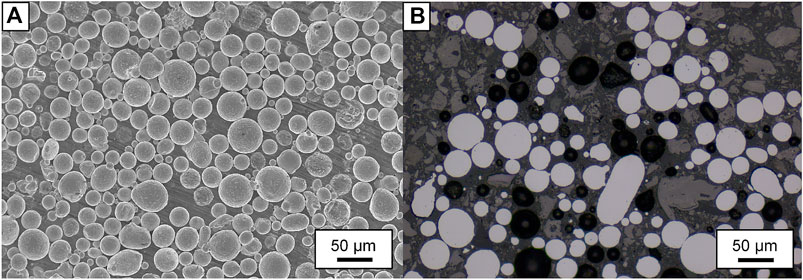
FIGURE 1. (A) Characteristic SEM micrograph showing the spherical morphology of Fe-1.1C powder. (B) Characteristic cross-sections of Fe-1.1C powder showing an absence of internal defects.
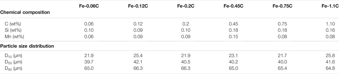
TABLE 1. Chemical composition and particle size distribution of the studied Fe-C powders.
Using these powder grades, 5 × 5 × 5 mm3 specimens were built using an EOS M100 machine that was provided by EOS GmbH, Germany. This machine is equipped with an Yb-fiber laser that has a maximum laser power of 200 W and a beam diameter of ∼40 μm. During processing, no build plate preheating was used, and an oxygen level of ∼0.1% was maintained within the building chamber using Ar gas. Regarding the scanning strategy, a stripe scan pattern was employed along with a scan rotation angle of 67°. No outer-skin or top-skin parameter was used during exposure.
To relate the types of defects to the processing parameters, volumetric energy density (VED) was used to represent the energy input during LB-PBF. The VED is a function of the scan speed (v), hatch spacing (h), layer thickness (t), and laser power (P):
A previous study on iron powder (Hearn et al., 2019) identified an adequate layer thickness of 20 μm and hatch spacing of 70 μm that could achieve >99% specimen density when using an EOS M100 machine. Using these values, and a laser power of 110 W, the VED was varied from 60 to 200 J/mm3 (in increments of 10 J/mm3) by varying the scan speed.
Characterization of the microstructure was carried out on XZ specimen cross-sections that had been mounted and polished down to 1 µm with diamond paste using a Struers TegraPol machine. Selected specimens were further etched with Nital (3%). Imaging of specimen cross-sections was conducted with a Zeiss Axiovision 7 light optical microscope (OM).
Density of the as-built specimens was measured using image analysis of un-etched XZ specimen cross-sections. This technique was chosen following the results of Kasperovich et al. (Kasperovich and Hausmann, 2015), which showed the relatively high accuracy of this technique when compared with computer tomography analysis. The shape descriptor plugin of ImageJ software (Schneider et al., 2012) was used to quantify the pore characteristics of Fe-C alloy specimens produced at 60, 80, 110, 150 and 200 J/mm3. During said image analysis, pores smaller than 20 μm2 were filtered out to reduce noise and cracks were excluded. Each analyzed image had a resolution of at least 1.08 µm/pixel.
Measurement of the melt pool depth was conducted using the top layer of etched specimen cross-sections, see Figure 2. For each parameter, 10–15 melt pool depth measurements were conducted.
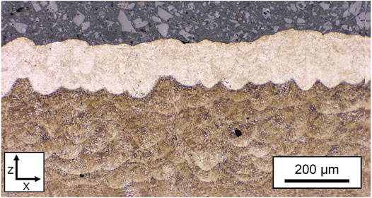
FIGURE 2. OM image of the top layer in an etched Fe-0.45C specimen produced at 130 J/mm3.
Fractography specimens were prepared using a 1–2 mm incision on the specimen surface in an orientation that was parallel to a crack on the opposite surface. This was used to initiate fracturing of the specimen to reveal the crack fracture surface. Once fractured, the specimens were evaluated using a Leo Gemini 1,550 high-resolution scanning electron microscope (SEM).
Simulation of the surface tension for the studied alloys was carried out using JMatPro v.11 software using the General Steel module, while simulation of the liquidus temperature and dynamic viscosity was conducted using ThermoCalc 2020b software using the TCFE10 database (Andersson et al., 2002).
The oxygen content of the powder feedstock and as-built specimens produced at 60 J/mm3 was measured by means of inert gas fusion using a LECO ON836 elemental analyser, in accordance with the EN 10276-2 standard.
Two sets of Vickers hardness measurements were performed using a DuraScan 70-G5 machine. The first set involved 12 HV10 indentations on XZ specimen cross-sections, with the indentations being spaced 1 mm apart. While the second set involved six HV0.1 indentations above and below revealed cracks, with the indentations being spaced 0.1 mm apart.
Results
Effect of VED on Porosity
At low VED, see Figure 3, the as-built specimens displayed low specimen density (<99%), as they contained numerous large and irregular pores, see Figure 4A. These shape characteristics, combined with the presence of un-melted and partially sintered powder particles, see Figure 4B, helped identify them as lack of fusion based porosity. Specimens produced at high VED also displayed a lower specimen density (<99.5%), where an examination of specimen cross-sections revealed the presence of oval-shaped, medium-sized pores (<100 µm), see Figure 4C. Nital etching further revealed that these pores were located at the bottom of the melt pool boundaries, see Figure 4D, helping to identify them as keyhole porosity. Between these VED ranges, the fabrication of high density (>99.8%) specimens that were relatively pore-free could be achieved.
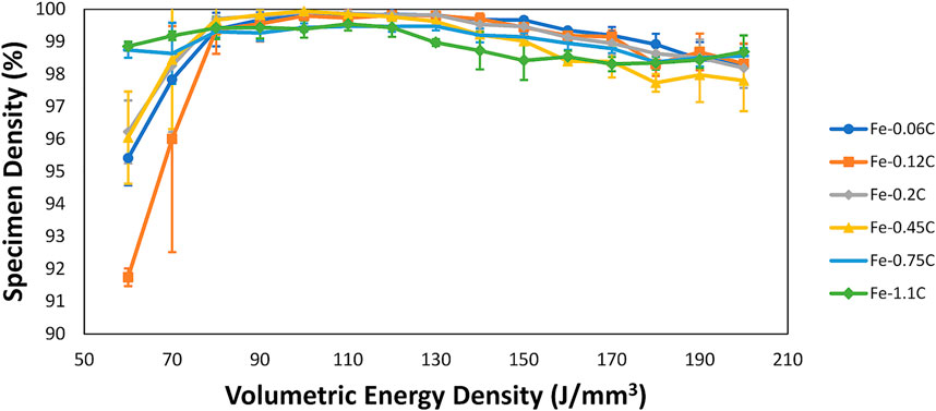
FIGURE 3. Change in specimen density with VED for the studied Fe-C alloys.
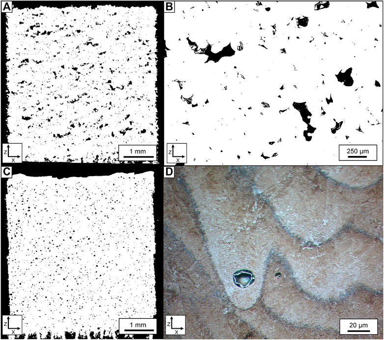
FIGURE 4. (A) Collection of large, irregular pores related to lack of fusion porosity in an Fe-0.45C alloy produced at 60 J/mm3. (B) Higher magnification of (A) showing the presence of un-melted and partially sintered powder particles within some lack of fusion pores. (C) Collection of rounded pores related to keyhole porosity in an Fe-0.45C alloy produced at 170 J/mm3. (D) Etching and higher magnification of (C) showing that these pores were predominantly located at the bottom of melt pool boundaries.
Effect of Carbon Content on Porosity
In addition to the VED, specimen density was dependent upon the carbon content, see Figure 3. To quantify this effect, image analysis of internal porosity was conducted on specimens produced at 60, 80, 110, 150, and 200 J/mm3. From this analysis, two major effects of the carbon content were identified. At low VED, the specimen density improved when higher carbon contents were used (>0.45 wt% C). This was observed in specimens produced at 60 J/mm3, as porosity became less numerous, more rounded, and smaller in size as the carbon content increased, see Table 2; Figure 5. This, combined with examinations of specimen cross-sections, see Figure 6, helped identify that higher carbon content reduces the formation of lack of fusion porosity. The second effect was that increasing the carbon content promoted the formation of the keyhole porosity at lower VED, see Figure 6. This was observed in specimens produced at 150 J/mm3 as image analysis and analysis of specimen cross-sections, see Table 3; Figure 5 reveals that pores became more numerous and larger in size and had a higher area fraction as the carbon content increased.
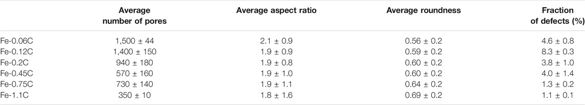
TABLE 2. Pore characteristics of specimens produced at 60 J/mm3.
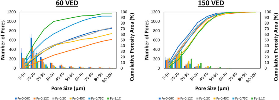
FIGURE 5. Histogram and cumulative porosity area of Fe-C alloy specimens produced at 60 J/mm3 (left) and 150 J/mm3 (right).
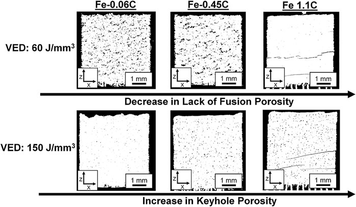
FIGURE 6. Cross-sections of specimens produced at 60 J/mm3 revealed a decrease in lack of fusion porosity with increasing carbon content (top). Cross-sections of specimens produced at 150 J/mm3 revealed an increase in keyhole porosity with increasing carbon content (bottom).

TABLE 3. Pore characteristics of specimens produced at 150 J/mm3.
Effect of Carbon Content on Melt Pool Properties
Simulation of the melt pool properties was conducted using JMatPro and ThermoCalc software. These analyses, see Table 4, indicate that increasing the carbon content would lower the liquidus temperature, surface tension (γ), and dynamic viscosity (µ) of the Fe-C alloys. Additionally, measurement of the oxygen content showed that increasing the amount of carbon reduced oxygen within the as-built specimens, regardless of how much oxygen was present within the original powder, see Table 4.
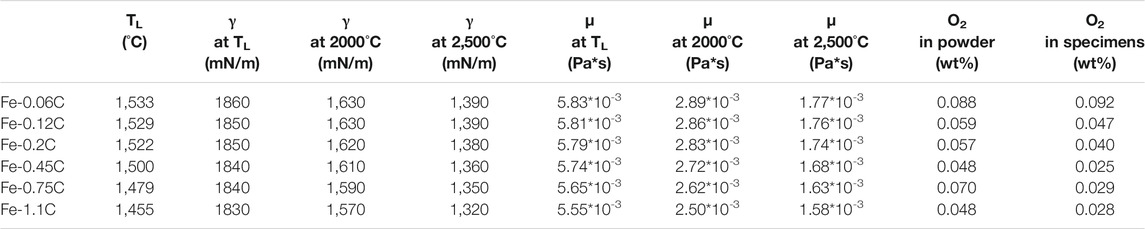
TABLE 4. Simulated liquidus temperature, surface tension, dynamic viscosity, and measured oxygen content within the powder and within specimens produced at 60 J/mm3 for each Fe-C alloy.
Effect of Carbon Content and VED on Cold Cracking
Cracking was observed in Fe-0.45C alloy specimens produced at VEDs below 90 J/mm3, see Figure 7, and was observed in all Fe-0.75C and Fe-1.1C alloy specimens. These cracks originated at the specimen edge and stretched towards the specimen center, see Figure 8A. Microhardness measurements, see Figure 8B, across the crack interface showed a similar hardness above and below the crack for the Fe-0.45C (above: 507 ± 16, below: 503 ± 28), Fe-0.75C (above: 540 ± 16, below: 526 ± 29), and Fe-1.1C alloys (above: 603 ± 20, below: 616 ± 12). This, combined with the uniform microstructure across the crack interface, see Figure 8C, pointed to a post-solidification, cold cracking phenomenon. This was confirmed via fractography analysis of the Fe-C alloys with ≥0.45 wt% C, see Figure 9, where transgranular ductile fracture with characteristic fine dimples was registered as the main micro-failure mechanism. Additionally, the fracture surfaces revealed the presence of small fractions of cleavage facets, which is typical for martensitic failure. This is in good correlation with the observed fine martensitic microstructure of the as-built Fe-C alloy specimens.
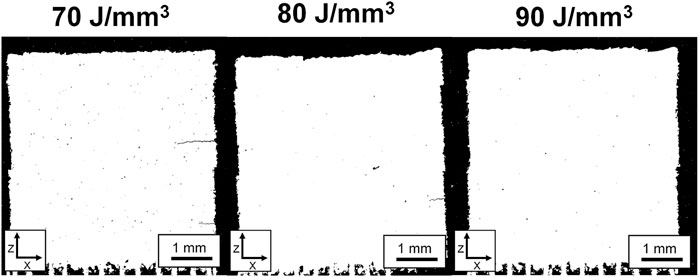
FIGURE 7. The size and number of cold cracks within the Fe-0.45C alloy specimens steadily decreased as the VED increased, until cold cracking was no longer observed at a VED of 90 J/mm3.
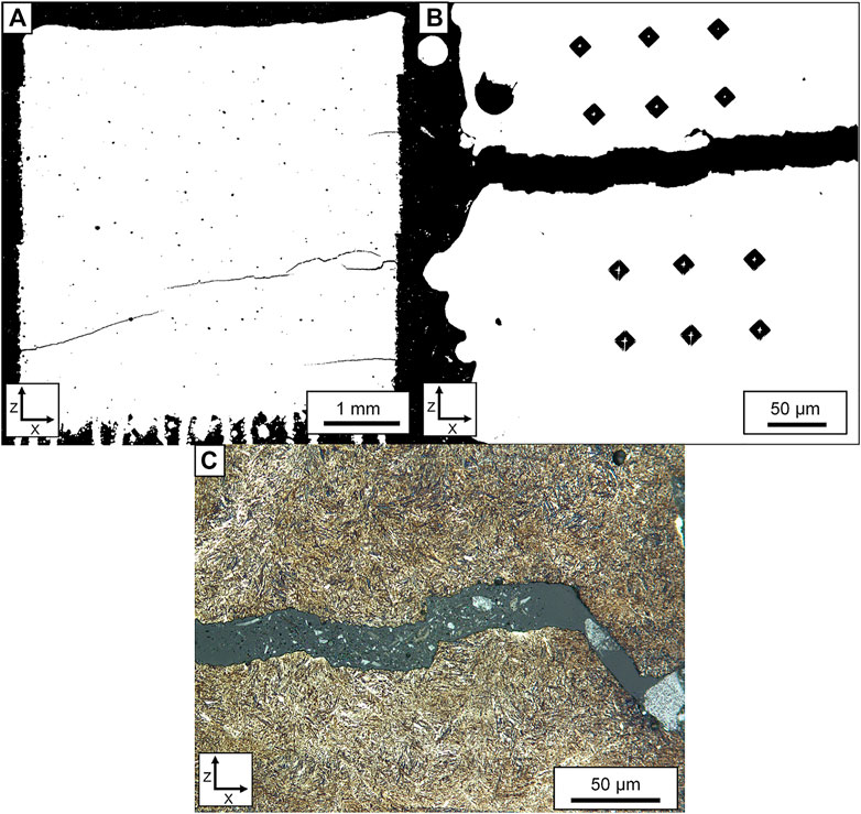
FIGURE 8. (A) Cracking in the Fe-1.1C alloy specimen produced at 120 J/mm3. (B) Example of microhardness indentations done across a crack interface from the specimen in (A). (C) Etched image of the microstructure across a crack from the specimen in (A).
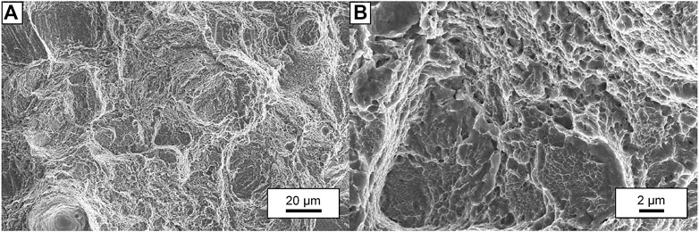
FIGURE 9. SEM images of the induced fracture surface for an Fe-0.75C specimen produced at 160 J/mm3: (A)1.5 kx magnification and (B) 10 kx magnification. From these fractures surface, we see that transgranular ductile fracture is the main micro-failure mechanism, as numerous fine dimples can be observed across the fracture surface. Higher magnification of the fracture surface in (B) also revealed the presence of some cleavage facets
To better understand the cause of this increased susceptibility to cold cracking, the melt pool depth and hardness of each Fe-C alloy specimen was measured, see Figure 10. These results found that increasing the VED would increase the melt pool depth and decrease the hardness of the as-built specimens. While increasing the carbon content was found to increase the melt pool depth and increase the hardness of the as-built specimens.
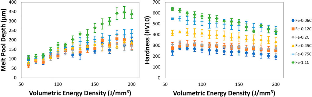
FIGURE 10. Change in melt pool depth and specimen hardness as a function of the VED.
Processing Window
Combining the presented results, a processing window for the Fe-C system was established that produced high density (>99.8%), defect-free specimens. Generally, increasing the VED decreased the crack susceptibility of the Fe-C alloys. Additionally, it caused a shift in porosity from lack of fusion at low VED to keyhole at high VED. As for the carbon content, increasing its amount limited the formation of lack of fusion porosity at low VED and lowered the VED that lead to keyhole porosity. Additionally, it would increase the crack susceptibility of the Fe-C alloys. These trends are represented in Figure 11 which outline the conditions for certain defects to form, as well as the conditions that produce high density, defect-free specimens in terms of the carbon content and the VED.
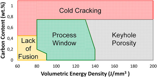
FIGURE 11. LB-PBF process window for the Fe-C system as a function of the carbon content and the VED.
Discussion
During LB-PBF of Fe-C alloys, the formation of porosity and cold cracking can occur depending upon the VED and the carbon content. Regarding the formation of porosity, it was observed that most Fe-C alloy specimens produced at low VED contained many lack of fusion pores, see Figure 4A, while specimens produced at high VED contained many keyhole pores, see Figure 4C. The formation of lack of fusion porosity at low VED is the result of an insufficient energy input to achieve proper bonding between deposited layers or between deposited melt tracks. Inter-layer lack of fusion occurs when the penetration of the melt pool is insufficient, while lack of fusion between melt tracks occurs when the overlap between melt pools is insufficient. In this work, the observed lack of fusion porosity is likely the result of insufficient overlap between melt tracks, as the smallest melt pool depths were still larger than the applied layer thickness (20 µm), see Figure 10. To avoid lack of fusion porosity between melt tracks, a sufficiently large VED was required, see Figure 3, as increased energy inputs will increase not only the melt pool depth but also the melt pool width (Ryder et al., 2021) (Keshavarzkermani et al., 2019).
Regarding the formation of keyhole porosity, this type of pore forms due to instabilities of the vapor depression during keyhole mode of melting (King et al., 2014) (Gordon et al., 2020), where increasing the energy input will increase the likelihood and depth of the vapor depression of the melt pool (Cunningham et al., 2019). In this work, increasing the VED was found to increase the depth of the melt pool, see Figure 10, pointing to an increased likelihood of keyhole mode melting that subsequently increases the likelihood of keyhole pores to form within the as-built specimens.
In addition to the VED, it was observed that porosity was influenced by the carbon content, where increasing the carbon content reduced the formation of lack of fusion porosity and increased the susceptivity to form keyhole porosity, see Figure 6. The reduction in lack of fusion porosity is due to the effect of carbon on the wetting behavior and viscosity of the melt pool. The wetting behavior of a liquid is primarily controlled by its surface tension, where a lower surface tension improves wetting behavior (Das, 2003). JMatPro simulations showed that a reduction in surface tension is achieved when the carbon content is increased, see Table 4. Similar improvements in wettability during LB-PBF were observed by Nakamoto et al. (2009), where increasing the carbon content of carbon steel enhanced the wetting between adjacent melt tracks, as well as the wetting between a melt track and the substrate. Another benefit of increased carbon content is that it will lower the amount of surface oxide within the melt pool, as the amount of oxygen within the as-built specimens was greatly reduced at higher carbon contents, see Table 4. This is important as oxygen within the melt can severely impede wettability, as a liquid will not wet surface oxide films (Das, 2003). Lastly, increasing the carbon content was found to improve the flowability of the melt pool, which is related to the liquid viscosity (Das, 2003) (Gu et al., 2012). ThermoCalc simulations showed that a reduction in viscosity is achieved when increasing the carbon content, see Table 4. This noticeably improves the infiltration and densification behavior of the melt pool, making it easier for lack of fusion pores to be filled in by the liquid during the deposition of a melt track.
Regarding the increase in keyhole porosity, it was observed that the melt pool depth increased as the carbon content increased, see Figure 10. This deeper melt pool could signify an increased likelihood of unstable keyhole mode melting, which can lead to the formation of keyhole pores. A potential cause of this is the depression of the liquidus temperature with increasing carbon content, see Table 4. However, the change in the liquidus temperature reached up to only ∼80°C and cannot fully explain the dramatic shift in the melt pool depth. As such, this increased susceptibility to form keyhole porosity at elevated carbon content still needs further exploration.
In addition to porosity, cracking defects were observed in select Fe-C alloy specimens. These cracks could be related to a cold cracking phenomenon due to the similar microstructure on either side of the crack, see Figure 8C, along with the observed fracture surfaces, see Figure 9. The formation of these cold cracks was influenced by the carbon content and the VED, where increasing the carbon content and lowering the VED would increase crack susceptibility.
The increase in crack susceptibility with increasing carbon content is related to a higher alloy hardenability and a higher martensite hardness. Regarding the effect on hardenability, increasing the carbon content depresses the formation of both pearlite and ferrite, promoting the formation of martensite during quenching. As for the effect on hardness, past works found that the hardness of quenched martensite will increase proportionally with the carbon content up to ∼0.6 wt% (Grange et al., 1977). Above this carbon content, alloy hardness will still increase but not to the same extent as the martensite transformation gets depressed to lower temperatures, causing the incomplete transformation of austenite to martensite. This leaves behind retained austenite that will lower the overall hardness of the material, even though the hardness of martensite is still high.
Regarding the reduced crack susceptibility with increasing VED, this is related to the intrinsic heat treatment that occurs during LB-PBF. Due to the layer-by-layer approach of the process, deposited material experiences cyclic reheating that involves many short spikes in temperature as new layers of material are melted (Krakhmalev et al., 2015) (Hocine et al., 2021). This induces an in situ tempering effect, where the level of tempering is controlled by amount of reheating that takes place during layer melting. For the Fe-C alloys, the melt pool depth increased as the VED increased, see Figure 10. This meant that at higher VED a larger volume of material was reheated, lowering the thermal gradient and cooling rate, and providing an enhanced intrinsic heat treatment. This enhanced in situ tempering was observed from hardness measurements, as the hardness of all Fe-C alloys decreased as the VED increased, see Figure 10.
Controlling the specimen hardness by varying the carbon content and/or VED was the decisive factor for cold cracking, as a threshold of around 425 HV could define whether cracking occurred. All Fe-0.75C and Fe-1.1C alloy specimens were above said threshold, along with all Fe-0.45C alloy specimens produced below 90 J/mm3. This indicates that in the absence of build plate preheating the carbon content and VED must be tailored to maintain a martensite hardness that can accommodate the residual stresses of LB-PBF without cracking. For the Fe-0.75C and Fe-1.1C alloys, the production of defect-free alloys was not possible due to the presence of cold cracking. However, it was possible to process these alloys relatively pore-free, meaning that if cracking could be avoided, they could be produced high-density and defect-free via LB-PBF. To achieve this, the application of build plate preheating is required, as this would help lower specimen hardness as well as the magnitude of the internal residual stresses.
Conclusion
In this study, LB-PBF processability of Fe-C alloys, with carbon contents between 0.06 and 1.1 wt%, was studied as a function of the carbon content and the VED. The conclusions of this investigation can be summarized as follows:
- Analysis of specimen porosity revealed that at low VED there was the noticeable presence of lack of fusion porosity, while at high VED there was a noticeable presence of keyhole porosity. In between these VEDs, pore-free specimens were produced.
- Increasing the carbon content limited the formation of lack of fusion porosity at low VED, while also increasing the susceptibility to form keyhole porosity. The reduction in lack of fusion porosity was due to improved wettability and flow of the melt pool as more carbon will lower the surface tension, viscosity, and oxygen content in the melt pool. Regarding the increase in keyhole porosity, this is believed to be caused by a reduction in the melting temperature and corresponding increase in the melt pool depth as the carbon content increases.
- Cold cracking was observed in Fe-C alloys with carbon content above 0.45 wt% C and would occur in specimens with a hardness ≥425 HV. High carbon content increased the crack susceptibility of the studied alloys. This was due to the increase in martensite hardness, which combined with the residual stresses from LB-PBF, inevitably led to the formation of cracking defects. Increasing the VED reduced the susceptibility to cold cracking, as larger VEDs enhanced the intrinsic heat treatment during LB-PBF, which assisted in lowering the hardness of the as-built specimens.
- From these results, a process window was established for each of the alloys (<0.75 wt% C) that could produce high density (>99.8%), defect-free specimens without the requirement of build plate preheating. Application of build plate preheating is believed to further increase the process window of studied Fe-C alloys to produce high density, defect-free specimens at elevated carbon contents (>0.75 wt% C).
Data Availability Statement
The original contributions presented in the study are included in the article/Supplementary Material. Further inquiries can be directed to the corresponding author.
Author Contributions
WH: conceptualization, investigation, formal analysis, and writing—original draft. EH: conceptualization, methodology, writing—review and editing, supervision, project administration, and funding acquisition.
Funding
This study was conducted in the frame of the Centre for Additive Manufacturing—Metal (CAM2), supported by the Swedish Governmental Agency of Innovation Systems (Vinnova).
Conflict of Interest
The authors declare that the research was conducted in the absence of any commercial or financial relationships that could be construed as a potential conflict of interest.
Publisher’s Note
All claims expressed in this article are solely those of the authors and do not necessarily represent those of their affiliated organizations, or those of the publisher, the editors and the reviewers. Any product that may be evaluated in this article, or claim that may be made by its manufacturer, is not guaranteed or endorsed by the publisher.
Acknowledgments
The authors would also like to thank and acknowledge Höganäs AB for providing the feedstock Fe-C powder and would like to thank Anton Dahl-Jendelin (RISE-IVF) for helping characterize the powder properties.
Supplementary Material
The Supplementary Material for this article can be found online at: https://www.frontiersin.org/articles/10.3389/fmats.2021.800021/full#supplementary-material
References
A. I. H. Committee (1990). ASM Handbook, Volume 01 - Properties and Selection: Irons, Steels, and High-Performance Alloys. Novelty, USA: ASM International.
Andersson, J.-O., Helander, T., Höglund, L., Shi, P., and Sundman, B. (2002). Thermo-Calc & DICTRA, Computational Tools for Materials Science. Calphad 26, 273–312. doi:10.1016/s0364-5916(02)00037-8
Cunningham, R., Zhao, C., Parab, N., Kantzos, C., Pauza, J., Fezzaa, K., et al. (2019). Keyhole Threshold and Morphology in Laser Melting Revealed by Ultrahigh-Speed X-ray Imaging. Science 363, 849–852. doi:10.1126/science.aav4687
Das, S. (2003). Physical Aspects of Process Control in Selective Laser Sintering of Metals. Adv. Eng. Mater. 5 (10), 701–711. doi:10.1002/adem.200310099
Dörfet, R., Zhang, J., Clausen, B., Freisse, H., Schumacher, J., and Vollersten, F. (2019). Comparison of the Fatigue Strength between Additively and Conventionally Fabricated Tool Steel 1.2344. Additive Manfuacturing 27, 217–223. doi:10.1016/j.addma.2019.01.010
Gordon, J., Narra, S., Cunningham, R., Liu, H., Chen, H., Suter, R., et al. (2020). Defect Structure Process Maps for Laser Powder Bed Fusion Additive Manufacturing. Additive Manufacturing 36, 101552. doi:10.1016/j.addma.2020.101552
Grange, R. A., Hribal, C. R., and Porter, L. F. (1977). Hardness of Tempered Martensite in Carbon and Low-alloy Steels. Mta 8, 1775–1785. doi:10.1007/bf02646882
Gu, D. D., Meiners, W., Wissenbach, K., and Poprawe, R. (2012). Laser Additive Manufacturing of Metallic Components: Materials, Processes and Mechanisms. Int. Mater. Rev. 57 (3), 133–164. doi:10.1179/1743280411y.0000000014
Hearn, W., Hryha, E., Bengtsson, S., and Nyborg, L. (2019). Processability & Microstructure of Fe-C System via L-PBF. EuroPM Proc. 2019.
Hocine, S., Van Swygenhoven, H., and Van Petegem, S. (2021). Verification of Selective Laser Melting Heat Source Models with Operando X-ray Diffraction Data. Additive Manufacturing 37, 101747. doi:10.1016/j.addma.2020.101747
Jamshidinia, M., Sadek, A., Wang, W., and Kelly, S. (2015). Additive Manufacturing of Steel Alloys Using Laser Powder-Bed Fusion. Adv. Mater. Process. 173, 20–24.
Kasperovich, G., and Hausmann, J. (2015). Improvement of Fatigue Resistance and Ductility of TiAl6V4 Processed by Selective Laser Melting. J. Mater. Process. Tech. 220, 202–214. doi:10.1016/j.jmatprotec.2015.01.025
Kempen, K., Vrancken, B., Buls, S., Thijs, L., Van Humbeeck, J., and Kruth, J.-P. (2014). Selective Laser Melting of Crack-free High Densit M2 High Speed Steel Parts by Baseplate Preheating. J. Manufacturing Sci. Eng. 136, 1–6. doi:10.1115/1.4028513
Keshavarzkermani, A., Marzbanrad, E., Esmaeilizadeh, R., Mahmoodkhani, Y., Ali, U., Enrique, P. D., et al. (2019). An Investigation into the Effect of Process Parameters on Melt Pool Geometry, Cell Spacing, and Grain Refinement during Laser Powder Bed Fusion. Opt. Laser Tech. 116, 83–91. doi:10.1016/j.optlastec.2019.03.012
King, W. E., Barth, H. D., Castillo, V. M., Gallegos, G. F., Gibbs, J. W., Hahn, D. E., et al. (2014). Observation of Keyhole-Mode Laser Melting in Laser Powder-Bed Fusion Additive Manufacturing. J. Mater. Process. Tech. 214, 2915–2925. doi:10.1016/j.jmatprotec.2014.06.005
Krakhmalev, P., Yadroitsava, I., Fredriksson, G., and Yadroitsev, I. (2015). In Situ heat Treatment in Selective Laser Melted Martensitic AISI 420 Stainless Steels. Mater. Des. 87, 380–385. doi:10.1016/j.matdes.2015.08.045
Krell, J., Röttger, A., Geenen, K., and Theisen, W. (2018). General Investigations on Processing Tool Steel X40CrMoV5-1 with Selective Laser Melting. J. Mater. Process. Tech. 255, 679–688. doi:10.1016/j.jmatprotec.2018.01.012
Li, X., Hao Tan, Y., Willy, H., Wang, P., Lu, W., Cagirici, M., et al. (2019). Heterogeneously Tempered Martensitic High Strength Steel by Selective Laser Melting and its Micro-lattice: Processing, Microstructure, superior Performance and Mechanisms. Mater. Des. 178, 1–13. doi:10.1016/j.matdes.2019.107881
Mertens, R., Vrancken, B., Holmstock, N., Kinds, Y., Kruth, J.-P., and Van Humbeeck, J. (2016). Influence of Powder Bed Preheating on Microstructure and Mechanical Properties of H13 Tool Steel SLM Parts. Phys. Proced. 83, 882–890. doi:10.1016/j.phpro.2016.08.092
Nakamoto, T., Shirakawa, N., Miyata, Y., and Inui, H. (2009). Selective Laser Sintering of High Carbon Steel Powders Studied as a Function of Carbon Content. J. Mater. Process. Tech. 209, 5653–5660. doi:10.1016/j.jmatprotec.2009.05.022
Narvan, M., Al-Rubaie, K. S., and Elbestawi, M. (2019). Process-Structure-Property Relationships of AISI H13 Tool Steel Processed with Selective Laser Melting. Materials (Basel) 12 (12), 1–20. doi:10.3390/ma12142284
Rombouts, M., Kruth, J. P., Froyen, L., and Mercelis, P. (2006). Fundamentals of Selective Laser Melting of Alloyed Steel Powders. CIRP Ann. 55 (1), 187–192. doi:10.1016/s0007-8506(07)60395-3
Ryder, M. A., Montgomery, C. J., Brand, M. J., Carpenter, J. S., Jones, P. E., Spangenberger, A. G., et al. (2021). Melt Pool and Heat Treatment Optimization for the Fabrication of High-Strength and High-Toughness Additively Manufactured 4340 Steel. J. Materi Eng. Perform. 30, 5426–5440. doi:10.1007/s11665-021-05836-8
Schneider, C. A., Rasband, W. S., and Eliceiri, K. W. (2012). NIH Image to ImageJ: 25 Years of Image Analysis. Nat. Methods 9, 671–675. doi:10.1038/nmeth.2089
Simchi, A., and Pohl, H. (2004). Direct Laser Sintering of Iron-Graphite Powder Mixture. Mater. Sci. Eng. A 383, 191–200. doi:10.1016/j.msea.2004.05.070
Keywords: additive manufacturing, laser based powder bed fusion, Fe-C alloys, steel, lack of fusion, keyhole porosity, cold cracking, intrinsic heat treatment
Citation: Hearn W and Hryha E (2022) Effect of Carbon Content on the Processability of Fe-C Alloys Produced by Laser Based Powder Bed Fusion. Front. Mater. 8:800021. doi: 10.3389/fmats.2021.800021
Received: 22 October 2021; Accepted: 22 November 2021;
Published: 03 January 2022.
Edited by:
Dongchan Jang, Korea Advanced Institute of Science and Technology, South KoreaReviewed by:
Yujing Liu, Changsha University of Science and Technology, ChinaAmir Motallebzadeh, Koç University, Turkey
Copyright © 2022 Hearn and Hryha. This is an open-access article distributed under the terms of the Creative Commons Attribution License (CC BY). The use, distribution or reproduction in other forums is permitted, provided the original author(s) and the copyright owner(s) are credited and that the original publication in this journal is cited, in accordance with accepted academic practice. No use, distribution or reproduction is permitted which does not comply with these terms.
*Correspondence: William Hearn, hearn@chalmers.se