Effect of Fibre Types on the Tensile Behaviour of Engineered Cementitious Composites
 Mingzhang Lan1*
  Jian Zhou
 Mingfeng Xu
- 1College of Materials Science and Engineering, Beijing University of Technology, Beijing, China
- 2School of Civil and Transportation Engineering, Hebei University of Technology, Tianjin, China
Engineered cementitious composite (ECC) is a group of ultra-ductile fibre-reinforced cementitious composites, characterised by high ductility and moderate content of short discontinuous fibre. The unique tensile strain-hardening behaviour of ECC results from a deliberate design based on the understanding of micromechanics between fibre, matrix, and fibre–matrix interface. To investigate the effect of fibre properties on the tensile behaviour of ECCs is, therefore, the key to understanding the composite mechanical behaviour of ECCs. This paper presents a study on the fibre-bridging behaviour and composite mechanical properties of ECCs with three types of fibres, including oil-coated polyvinyl alcohol (PVA) fibre, untreated PVA fibre, and polypropylene (PP) fibre. The experimental result reveals that various fibres with different properties result in difference in the fibre-bridging behaviour and composite mechanical properties of ECCs. The difference in the composite mechanical properties of ECCs with different fibres was interpreted by analysing the fibre-bridging behaviour.
Introduction
By deliberate design based on the understanding of micromechanics between fibre, matrix, and fibre–matrix interface, engineered cementitious composite (ECC) exhibits unique strain-hardening behaviour (Li, 2003). Under tensile load, ECC shows tensile strain-hardening behaviour and develops tensile strain capacity in the range of 3–7%, compared to 0.01–0.05% for ordinary concrete and fibre-reinforced concrete (FRC). Figure 1 illustrates the difference in the typical tensile stress–strain curves of ordinary concrete, FRC, and ECC (Fischer and Li, 2003). Ordinary concrete is a brittle material, and crack formation is followed by a sudden loss of load carrying capacity. Although tensile strength and fracture toughness are enhanced, to some extent, by adding fibre, FRC is, nevertheless, a quasi-brittle material, showing strain-softening single-cracking behaviour under tension. On the contrary, ECC has a metal-like feature. After the first crack forms in ECC, tensile load-carrying capacity rises as strain increases, through multiple-cracking process with tight crack width control. The crack width of ECC is self-controlled to below 100 μm without the presence of steel reinforcement, which is much smaller than the typical crack width observed in ordinary concrete and FRC (Weimann and Li, 2003; Xiao et al., 2021; Xiong et al., 2021).
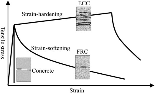
FIGURE 1. Typical tensile stress-strain curves of concrete, FRC, and ECC (Fischer and Li, 2003).
The unique tensile strain-hardening behaviour and tight crack width control of ECC result from an elaborate design using micromechanics model to tailor the interaction between fibre, matrix, and fibre–matrix interface (Li, 1993). The fibre-bridging properties play a crucial role on the tensile strain-hardening behaviour of ECC. When ECC is loaded in tension, the matrix starts to crack in its weakest cross-section. The fibre crossing this crack takes over the tensile load. Thanks to the engineered steady-state cracking behaviour, the fibre in this crack can carry an increasing load, which generates new cracks at other sites (Li and Leung, 1992). By repeating this process, ECC exhibits tensile strain-hardening multiple-cracking behaviour.
Several types of fibre have been used to produce ECC, and their properties are summarised in Table 1. The first version of ECC was made of high-modulus polyethylene (PE) fibre in the mid-1990s (Li et al., 1995; Li et al., 1996). Reinforced with 1.5% by volume of high-modulus PE fibre, PE-ECC exhibits tensile strain capacity ranging from 4 to 7%, tensile strength over 5.5 MPa, and compressive strength over 60 MPa. The PE fibre enables the ECC with superior mechanical properties. Therefore, PE-ECC with various features was developed, such as the PE-ECC prepared with seawater and sea sand with non-corrosion function (Huang et al., 2021), the PE-ECC prepared with artificial fine aggregates that reduces the industrial burden on the environment (Xu L.-Y. et al., 2021), the PE-ECC with ultra high dectility as a noval and resilient fireproof coating (Cai et al., 2021), and the PE/steel fibre-ECC with compressive strength over 210 MPa for complex and severe service environments (Huang, et al., 2021b). Considering the large crack width of PE-ECC due to the hydrophobic nature of PE fibre, and the high cost of the PE fibre, studies moved on for alternatives. In the early 2000s, Li and his co-workers have successfully developed a group of ECCs with polyvinyl alcohol (PVA) fibre, costing one-eight of the high-modulus PE fibre (Li et al., 2001). Since the surface of PVA fibre is hydrophilic, ordinary PVA fibre tends to rupture instead of pullout of a cementitious matrix due to the strong chemical bond with matrix, and this has a negative effect on the tensile ductility of ECC. The interfacial properties between PVA fibre and matrix were, therefore, tailored by applying 1.2% by weight of oil coating on the fibre surface (Li et al., 2002). ECC with the oil-coated PVA fibre exhibits tensile strain capacity of 3–5% and tensile strength of 4–5 MPa (Li et al., 2001). After Li’s work, many ECC materials with oil-coated PVA fibre have been developed in many institutions (Kim et al., 2003; Wang and Li, 2006; Kim et al., 2007; Yang et al., 2007; Zhang et al., 2009; Zhou et al., 2010). In recent years, several researchers have developed ECC materials with non-oil-coated PVA fibre, which exhibit comparable composite properties as oil-coated-PVA ECC (Ma et al., 2015; Pan et al., 2015; Said et al., 2015; Meng et al., 2017; Zhang and Zhang, 2018). Yang (2008) and Felekoglu et al. (2014) have developed a group of ECCs with high-tenacity polypropylene (PP) fibre. The high-tenacity PP fibre consists of a high strength core made of high molecular weight PP resin and an engineered sheath with/without surface coating (De Lhoneux et al., 2002). The high-tenacity PP fibre has a tensile strength of 850 MPa, about twice as high as that of ordinary PP fibre. ECC with the tenacity PP fibre showed multiple-cracking behaviour under tensile load and had tensile strain capacity over 4%, while the ultimate tensile strength was below 2.5 MPa, much lower than that of PE-ECC and PVA-ECC. Tosun-Felekoglu and Felekoglu (2013) have tried to develop ECC with ordinary PP fibre. Although their specimens showed deflection-hardening multiple-cracking behaviour under a four-point bending load, further studies are still needed to prove whether the composite has the strain-hardening multiple-cracking feature. Recently, a novel ECC with basalt fibre, an inorganic fibre, has been developed by Xu M. et al. (2021). Basalt fibre-ECCs show a tensile strain capacity of 0.4–0.9%, and an average crack width is <8 μm, about one order of magnitude smaller than typical ECCs prepared with PVA, PP, or PE fibres.
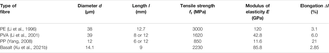
TABLE 1. Properties of fibre used in ECC.
This paper aims to investigate the mechanical properties of ECCs with different PVA and PP fibres and to reveal the effect of fiber types and properties on uniaxial tensile and fibre bridging properties of ECCs. First, the framework of the ECC micromechanics design guidelines is briefly reviewed. The mix design and experimental program are then described. The experimental results of uniaxial tensile tests, loaded crack width measurement, and bending and compressive tests are presented. The results of uniaxial tensile tests using notched specimens are also reported to estimate the bridging properties between fibre and matrix. Last, the comparison between the tensile properties of ECCs made of different fibres is discussed from the point of view of ECC micromechanics.
ECC Micromechanics
The ECC micromechanics model was established by Li and Leung in the early 1990s (Li and Leung, 1992) and has been successfully used in ECC material design by many researchers (Li et al., 1995; Li et al., 2001; Li et al., 2002; Wang and Li, 2006; Yang et al., 2007; Zhou et al., 2010; Ranade et al., 2013). The ECC micromechanics model links macroscale composite properties (tensile strength and strain capacity) to micromechanical properties (fibre-bridging parameters) based on the fundamental understanding of the mechanical interactions among fibre, matrix, and fibre–matrix interface. The scale linking represents the ECC material design philosophy: to understand the microscale behaviour and to tailor the micromechanical properties are the keys to designing targeted composite properties. The ECC micromechanics model consists of two guiding concepts, i.e., energy criterion and strength criterion.
Energy Criterion
The fundamental requirement for strain hardening and multiple cracking is that the cracks develop steady-state crack propagation rather than Griffith-type crack propagation (Li and Leung, 1992). Steady-state crack propagation refers to as that a crack increases in length at constant steady-state cracking stress σss while maintaining a constant crack opening δss. Marshall and Cox (1988) employed the J-integral method and proposed a general solution for the condition of steady-state crack propagation:
where Jtip is the crack tip toughness, and δss is the crack opening corresponding to the steady-state cracking stress σss.
Equation 1 expresses the energy balance (energy demanded and supplied to crack tip) per unit crack advance during steady-state crack propagation, as schematically illustrated in Figure 2. The right-hand side of Eq. 1 can be interpreted as the net energy input by external work (first term) minus the energy consumed by the bridging elements at the crack tip propagation zone from 0 to δss (second term), which is referred to as the complementary energy and represents the shaded area in Figure 2. The maximum complementary energy Jb′ occurs when the stress reaches the maximum fibre bridging strength σ0 in this crack and represents the hatched area in Figure 2, as follow:
where δ0 is the crack opening corresponding to the maximum fibre bridging strength σ0.
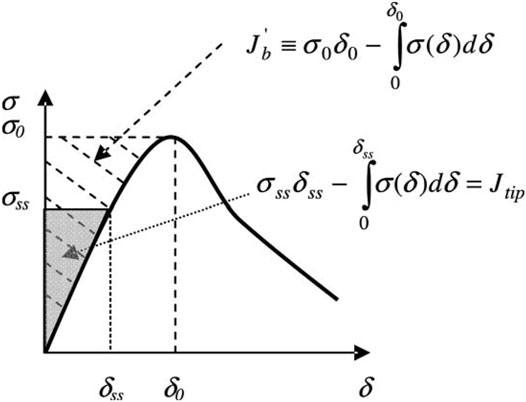
FIGURE 2. Typical bridging stress-crack opening σ(δ) curve for steady-state crack propagation. Hatched area represents complimentary energy Jb′. Shaded area represents crack tip toughness Jtip (Li and Leung, 1992).
In order to ensure steady-state crack propagation, the energy criterion requires that the available crack-driving, i.e., energy maximum complementary energy Jb′, should be greater than the energy required for crack propagation, i.e., crack tip toughness Jtip:
Strength Criterion
The strength criterion determines the initiation of cracks and requires that the matrix tensile cracking strength σc should be lower than the maximum fibre bridging strength σ0.
where the matrix tensile cracking strength σc is determined by the matrix fracture toughness and the pre-existing flaw size, such as air voids.
Materials and Methods
Materials
One single cementitious matrix was used in this study, and the mix proportion is given in Table 2. The matrix was made of ordinary Portland cement, fly ash, and silica fume mixed with water at the water-to-powder ratio of 0.175. A polycarboxylate superplasticiser was also added to adjust the fresh properties of the mixtures until the flowability of the mixtures reached 190 ± 5 mm. Flowability test was conducted according to ASTM C 1437 (ASTM C 1437, 2007).

TABLE 2. Mix composition of the matrix.
Two PVA fibres and one PP fibre were used in the experimental program, and their properties are given in Table 3. Fibre “PVA1” was the 1.2 w% oil-coated PVA fibre with a surface oil coating of 1.2% by weight, and this fibre has been widely used in the studies on PVA-ECCs. Fibres “PVA2” and “PP” were ordinary PVA fibre and PP fibre manufactured by Chinese manufacturers. The tensile strength and elastic modulus of PVA1 fibre are higher than those of PVA2 fibre, while the diameter of the former is much larger than the latter. PP fibre has a relatively lower tensile strength and elastic modulus than two PVA fibres. The elongation ratio at break of PP fibre is considerably high.
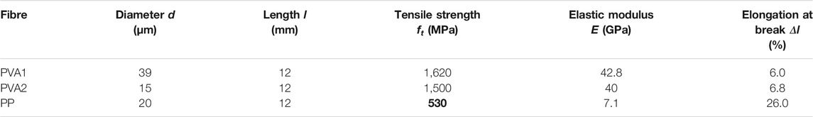
TABLE 3. Properties of the three fibres used in this study.
The effect of fibre content on the macroscale composite properties and microscale fibre-bridging properties of the composites was studied. Considering a typical PVA fibre content in ECCs is 2% by volume, the composites with 1, 1.5, 2, and 2.5% by volume of PVA1 fibre and PVA2 fibre were prepared. According to the strength criterion, a larger amount of PP fibre should be used, since PP fibre has a lower tensile strength and thereof a lower bridging strength in PP-ECC (Kanda and Li, 1999). PP fibre contents of 2, 2.5, 3, and 4% by volume were investigated.
Mixing, Casting, and Curing
Powder materials, water, and admixtures were first mixed in a 5-L mixer at a low speed for 1 min and at high speed for another 2 min. Then, fibre was evenly added within 1 min during low-speed mixing. Last, mixing is continued at high speed for another 2 min.
Prism specimens with the dimension of 160 mm × 40 mm × 40 mm were prepared for compression and three-point bending tests. Dogbone-shape specimens were prepared for uniaxial tension tests, recommended by the Japan Society of Civil Engineers (Yokota et al., 2008). Half of the dogbone-shape specimens (as shown in Figure 3 left) were used to evaluate the composite tensile properties, and another half of dogbone-shape specimens with two 10-mm-wide notches (as shown in Figure 3, right) were used to evaluate the fibre-bridging properties. The specimens were cured in a climate chamber with a temperature of 20°C and relative humidity above 95% for 24 h. After demoulded, the specimens were sealed in a plastic bag and cured in a room with a temperature of 20°C until the age of 28 days.
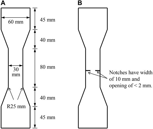
FIGURE 3. Dogbone-shape specimen (A) and notched dogbone-shape specimen (B).
Compression and Three-Point Bending Tests
The prism specimens were sawn into two pieces evenly, used for compression tests. Compression tests were conducted under load control with a loading speed of 2,400 N/ s. The loaded area was 40 mm × 40 mm. Six specimens were tested for each mixture, and the compressive strength was calculated by averaging the results of the six measurements.
The rest prism specimens were used in three-point bending tests for evaluating the flexural strength. The support span was 100 mm, and the load point was at the mid of support span. The test was conducted under load control with a loading speed of 50 N/ s. Three specimens were tested for each mixture, and the flexural strength was calculated by averaging the results of the three measurements.
Uniaxial Tension Test
Uniaxial tensile tests were conducted with the dogbone-shape specimens for investigating the tensile properties of the composites and the notched dogbone-shape specimens for investigating the fibre-bridging properties. The test procedure was the same for the two types of specimens. Two ends of the specimens were placed in two wedge clamp chucks. The upper and lower clamps were connected to the loading device with a pin joint and a fixed joint, respectively. One extensometer with a precision of 1 μm was attached on the specimen to measure the deformation, and the gauge length was 80 mm. The tests were conducted under displacement control with a loading speed of 0.004 mm/ s. The experimental results of each composite are calculated by averaging the data of six specimens.
Loaded Average Crack Width
Loaded average crack width was measured on the dogbone-shape specimens after uniaxial tension tests. The number of cracks within gauge length along the central axis was accounted under a microscope with a magnification of × 100. The average crack number N of each specimen was calculated by averaging the number of cracks on both sides. Since ECC deforms several hundred times larger than the matrix, the elastic deformation of the matrix contributes little to the overall deformation of the composites. Therefore, the overall tensile deformation can be simply considered as the sum of crack openings. Accordingly, the average crack width wc can be calculated by dividing the measured tensile deformation at the peak load Δl by the average crack number N:
Experimental Results
Compressive and Flexural Strengths
Figures 4, 5 give the 28-days compressive and flexural strengths of the composites with PVA1 fibre, PVA2 fibre, and PP fibre. In general, given the same fibre content, the composites with PVA1 fibre exhibited slightly higher compressive and flexural strengths than the composites with PVA2 fibre and the composites with PP fibre exhibited the lowest compressive and flexural strengths.
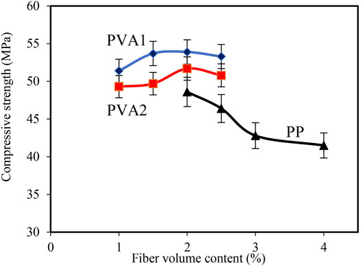
FIGURE 4. Compressive strength of the composites with PVA1 fibre, PVA2 fibre and PP fibre at 28 days.
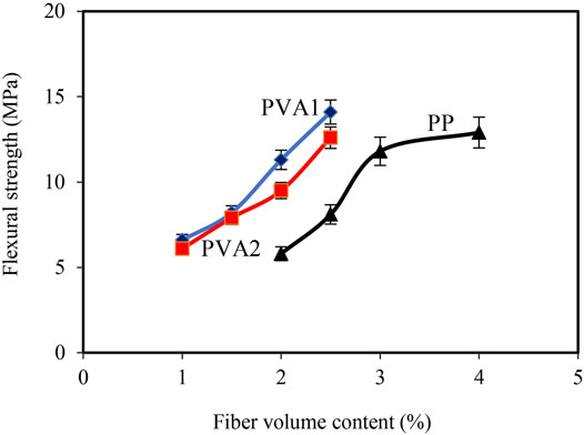
FIGURE 5. Flexural strength of the composites with PVA1 fibre, PVA2 fibre, and PP fibre at 28 days.
As PVA fibre content increased from 1 to 2.5% by volume, the compressive strength of the composites with PVA1 fibre and PVA2 fibre first increased and then decreased, and the former ranges from 51.4 to 53.9 MPa and the latter ranges from 49.3 to 51.7 MPa. The increase in the PP fibre content from 2 to 4% by volume caused a decrease in the compressive strength of the composites with PP fibre from 48.6 to 41.5 MPa. The increase in the content of the three fibres all resulted in an increase in flexural strength of the composites. The flexural strength of the composites with PVA1 fibre increased from 6.6 to 11.4 MPa, that of the composites with PVA2 fibre increased from 6.1 to 12.6 MPa, and that of the composites with PP fibre increased from 5.8 to 12.9 MPa.
Tensile Properties
Figure 6 shows a typical tensile stress–strain curve of the composites obtained from uniaxial tensile tests with dogbone-shape specimens. The maximum tensile stress in tensile stress–strain curves is defined as ultimate tensile strength, and the corresponding strain is defined as tensile strain capacity.
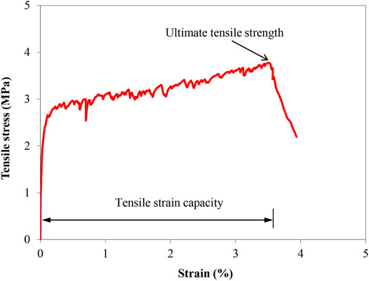
FIGURE 6. Typical tensile stress-strain curve of the composites obtained from uniaxial tensile tests with dogbone-shape specimens.
Supplementary Figures SA1–SA3 in Appendix show the tensile stress–strain curves of the composites with PVA1 fibre, PVA2 fibre, and PP fibre at 28 days. Table 4 summaries the experimental results of ultimate tensile strength, tensile strain capacity, and loaded average crack width of the composites. Except the composite with 2% by volume of PP fibre, the rest composites exhibited strain-hardening multiple-cracking behaviour. As fibre content increased, the composites with PVA1 fibre, PVA2 fibre, and PP fibre showed more pronounced strain-hardening multiple-cracking behaviour, manifested as increasing tensile strain capacity and decreasing average crack width. An acceptable strain-hardening multiple-cracking behaviour of the composites was achieved, when PVA fibre content was not lower than 1.5% or PP fibre content was not lower than 2.5%, preferably 2% or 3%, respectively.

TABLE 4. Uniaxial tensile test results of the composites with the three fibres at 28 days.
Given the same fibre content, the composites with PVA1 fibre exhibited higher ultimate tensile strength and greater tensile strain capacity than the composites with PVA2 fibre, while the average crack width in the former was more than two times larger than that in the latter. For instance, with 2% by volume of PVA fibre, the former had an ultimate tensile strength of 4.1 MPa, tensile strain capacity of 3.5%, and average crack width of 101.3 μm, and the latter had an ultimate tensile strength of 3.8 MPa, tensile strain capacity of 3.3%, and average crack width of 46.3 μm. Compared to the composites with the two PVA fibres, the composites with PP fibre exhibited a lower ultimate tensile strength, comparable tensile strain capacity, and larger average crack width.
Fibre-Bridging Properties
To interpret the tensile properties of the composites, the bridging properties between fibre and matrix were investigated by using uniaxial tension test with notched specimens. Figure 7 shows a typical fibre bridging stress–crack opening curves of the composites obtained from uniaxial tensile tests with notched dogbone-shape specimens. Matrix cracking strength is the tensile stress at the cracking of the matrix, and it relates to the tensile strength of the matrix. Fibre-bridging strength is the maximum tensile stress after cracking.
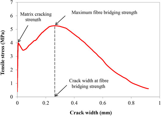
FIGURE 7. Fibre bridging stress-crack opening curves of the composites obtained from uniaxial tensile tests with notched dogbone-shape specimens.
Supplementary Figures SA4–SA6 in Appendix give the fibre bridging stress–crack opening curves of the composites with PVA1 fibre, PVA2 fibre, and PP fibre at 28 days. Table 4 summarises the experimental results of matrix cracking strength, fibre-bridging strength, and crack opening at fibre-bridging strength. The mixture with 2% by volume of PP fibre had a matrix cracking strength higher than the maximum fibre bridging strength. After the matrix cracks, the external load, which needs to exceed matrix cracking strength, must be higher than the maximum fibre bridging strength. Consequently, fibres in the crack cannot hold this external load, and the matrix exhibits single-cracking behaviour. On the contrary, the rest mixtures had a matrix cracking strength lower than maximum fibre bridging strength; after cracking, fibres in the cracks can hold the load higher than the matrix cracking strength and generate subsequent cracking.
The increase in fibre content led to no obvious negative influence on matrix cracking strength and a more pronounced increase in maximum fibre bridging strength. As shown in Figure 8, the fibre-bridging strength of the composites fell around to the fitting line, exhibiting a relationship that is close to linear to the content of three types of fibres, respectively. The experimental results also reveal that fibre content has no obvious influence on the crack opening at the maximum fibre bridging strength.
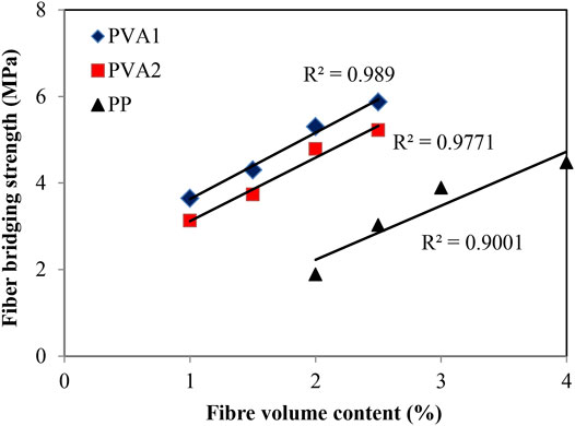
FIGURE 8. Relation of maximum fibre bridging strength to fibre content.
Given the same fibre content, the composites with PVA1 fibre exhibited similar matrix cracking strength and higher maximum fibre bridging strength than the composites with PVA2, while the crack opening at the fiber-bridging strength of the former was roughly two times larger than that of the latter. Compared to the composites with the two PVA fibres, the composites with PP fibre exhibited a lower matrix cracking strength and maximum fibre bridging strength and significantly larger crack opening at maximum fibre bridging strength.
In the condition that fibres are randomly oriented and pullout (rather than fibre rupture) are expected, the key parameters of the fibre bridging properties, the maximum fibre bridging strength σ0, and the crack opening corresponding to the maximum fibre bridging strength δ0, can be expressed as in Eqs 6, 7; (Li, 1992).
where g is the snubbing factor; τ is the fibre/matrix frictional bond strength; Lf, df, and Ef are the fibre volume fraction, length, diameter, and Young’s modulus, respectively. η = (VfEf)/(VmEm), where Vm and Em are the matrix volume fraction and Young’s modulus, respectively. From the above two equations, it can be seen that the maximum fibre bridging strength σ0 and its corresponding crack opening δ0 are determined by the fibre properties, such as its diameter, length, elastic modulus, and fibre/matrix bonding. In this study, the large diameter of PVA1 seems to negatively affect σ0, while the rest fibre properties overwhelmed and finally generated a relatively high bridging strength. Although the smaller diameter of PVA2 facilitates the bridging strength, a lower bridging strength was still obtained, due to its oil coating that reduces the fibre/matrix frictional bond (Yang, 2008). For PP fibre, its hydrophobic surface (Zhang et al., 2020) is not beneficial to the high fibre/matrix frictional bond or the high bridging strength as well. This does not mean that the oil coating or hydrophobic surface is undesirable. When considering fibre rupture, oil coating and hydrophobic surface contribute to preventing fibres from rupture and therefore a high ductility.
Discussion
The test results included in the previous section show that the composites with two PVA fibres and one PP fibre, up to a certain fibre content, can all exhibit multiple-cracking behaviour and tensile strain-hardening behaviour. Different fibres have led to different composite tensile properties and fibre-bridging properties. In this section, the relation of composite tensile properties and fibre-bridging behaviour is discussed from the point of view of ECC micromechanics reported in ECC Micromechanics.
As expressed in Eq. 4, the strength criterion requires that the matrix tensile cracking strength σc should be lower than the maximum fibre bridging strength σ0, and as expressed in Eq. 3, the energy criterion requires that the fracture energy of matrix Gm should be lower than the maximum complementary energy Jb’. These two criteria ensure the occurrence of multiple-cracking behaviour and tensile strain-hardening behaviour. The intensity of multiple cracking and the tensile ductility are, however, determined by the uniformity of the composites, in particular pre-existing flaw size distribution and fibre distribution. Due to the randomness nature of pre-existing flaw size and fibre distribution in composites, large margins between σ0 and σc and between Jb′ and Jtip are preferred for saturated multiple cracking and high tensile ductility. The strain-hardening indexes are, therefore, defined to quantitatively evaluate the margins:
The matrix tensile cracking strength σc and the maximum fibre bridging strength σ0 were estimated using uniaxial tension test with notched specimens, as given in Table 5. At small fibre content, appropriate for ECC, Jtip approached the matrix fracture energy Gm. Gm was calculated with matrix fracture toughness Km and elastic modulus Em in the term of Km2/Em, where Km was estimated using three-point bending test with notched beam specimens and was estimated using uniaxial tension test. The one single matrix used in the composites with three types of fibres had fracture energy of 28.2 J/ m2. Jb′ can be calculated by Eq. 2 with the fibre bridging stress–crack opening curves given in Fibre-Bridging Properties.
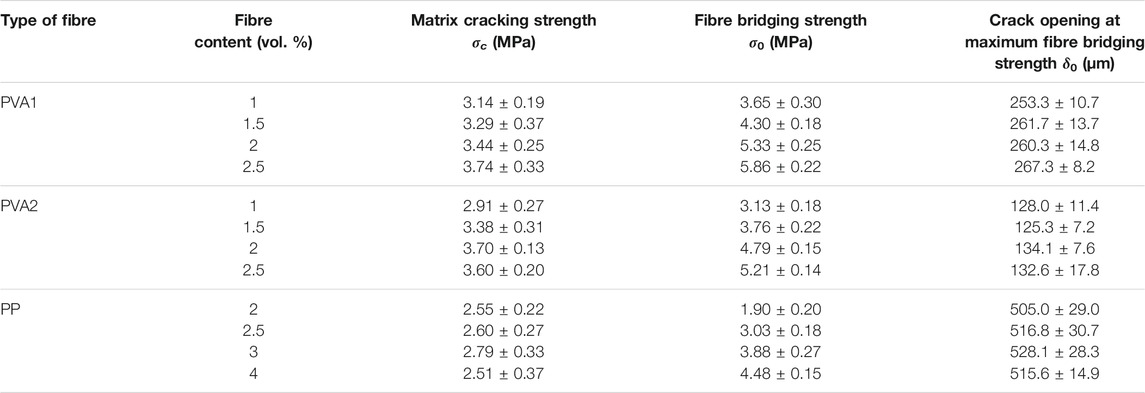
TABLE 5. Bridging properties between the three fibres and matrix at 28 days.
Among the composites with three types of fibres, only the composite with 2% PP fibre has a SHstrength below 1, and the strength criterion is, therefore, not satisfied. This explains why the composite with 2% PP fibre did not exhibit strain-hardening and multiple-cracking behaviour, while the rest of the composites did. Figure 9 gives the strain-hardening indexes SHstrength and SHenergy of the composites with different fibres (except the one with 2% PP fibre). For the three types of fibres, as the fibre content increases, both the strain-hardening indexes SHstrength and SHenergy increase. This agrees with the observation in tensile tests that the increased fibre content led to more pronounced strain-hardening multiply-cracking behaviour.
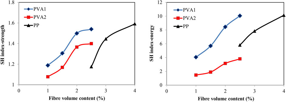
FIGURE 9. Strain-hardening indexes of the ECCs with different fibres.
The previous study suggested that PE fibre–ECCs need to have strain-hardening indexes SHstrength and SHenergy over 1.2, and three to produce good strain-hardening behaviour (Kanda and Li, 1998). For PVA fibre–ECCs, SHstrength is, however, required to be >1.45 due to lower tensile strength and higher interfacial bonds of PVA fibre compared with PE fibre (Li et al., 2002). As shown in Figure 10, the experimental results of this study reveal that for a strain capacity of 3%, the SHstrength of 1.45 also applies to PVA1 fibre, which is the same fibre as used in Li et al. (2002). For PVA2 fibre, this value is about 1.2, close to the value for PE fibres; while for PP fibre, this value is 1.45. The values of SHenergy for PVA1, PVA2, and PP fibres are 8, 3, and 8, respectively.
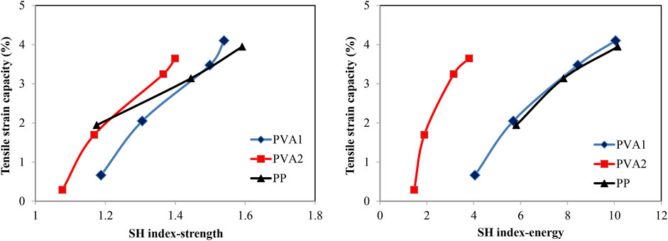
FIGURE 10. Relation of tensile strain capacity to strain-hardening indexes.
The crack opening at maximum fibre bridging strength δ0 is a parameter often used to describe the fibre-bridging properties. Once composite cracks under tension, the tensile load is transferred from matrix to fibres within the crack through fibre–matrix interfaces. When the crack width is smaller than δ0, the interfaces can carry higher load, due to the slip-hardening behaviour of PE, PVA, and PP fibres within matrix. This process eventually leads to strain-hardening and multiple-cracking behaviour of composites. When the crack width is beyond δ0, fibres are gradually pulled out of matrix, the load-carrying capacity of the interfaces declines, and composite fails. Therefore, during strain-hardening stage, all cracks in ECCs must be smaller than δ0. Like strength and energy criteria, a large margin between δ0 and crack width wc, which means a lower wc/δ0 ratio, is preferred for a higher tensile ductility, as shown in Figure 11.
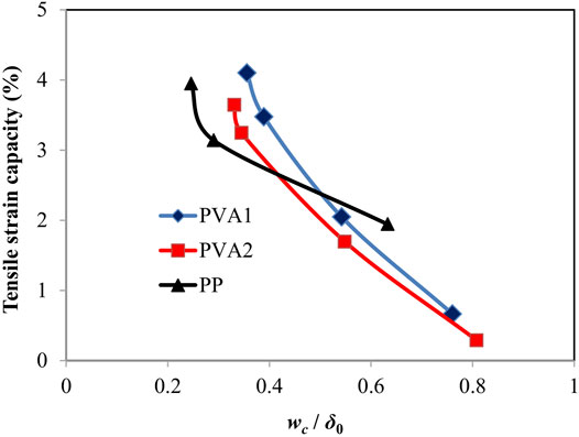
FIGURE 11. Relation of tensile strain capacity to the ratio of loaded average crack width we to crack opening at maximum fibre bridging strength δ0.
Besides, the trends of ultimate tensile strength and average crack width of ECC with different fibre types can be traced back to the fibre bridging properties. For ECC with PVA1, PVA2, and PP fibres at 2.5% fibre content, the crack opening at the maximum fibre bridging strength increases in the order of the PVA1 fibre, the PVA2 fibre, and the PP fibre. As can be seen in Figure 12, the average loaded crack width of the ECC composites with the three fibres increased in the same order. Figure 13 shows the ultimate tensile strength plotted against the maximum fibre bridging strength. The linear correction between the maximum fibre bridging strength and the ultimate tensile strength was evident. This implies that the ultimate tensile strength is largely governed by the variation of the maximum fibre bridging strength, which evolves with fibre types.
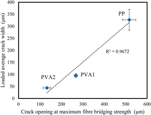
FIGURE 12. Correlation between crack opening at maximum fibre bridging strength and Loaded average crack width.

FIGURE 13. Correlation between maximum fibre bridging strength and ultimate tensile strength.
Conclusion
The paper presents the effect of fibre types on the compressive and tensile properties (macroscale) and the fibre-bridging properties (mesoscale) of ECC. Based on the experimental results and discussion, the following conclusions can be drawn:
1) Up to a certain fibre content, the composites with ordinary PVA fibre or PP fibre all exhibit strain-hardening multiple-cracking behaviour under uniaxial tensile load. Fibre volume contents of exceeding 1.5 and 2.5%, preferably 2 and 3%, are required for the composites with the PVA fibre and the PP fibre for a good ductility, respectively.
2) Given the fibre volume content of 2%, the composites with the oil-coated PVA fibre (39 μm in diameter) exhibit greater tensile strain capacity but fewer cracks with larger average crack width than the composites with the ordinary PVA fibre (15 μm in diameter). The former also has a higher compressive, tensile, and flexural strength than the latter.
3) The composites with 3% by volume of the ordinary PP fibre have lower tensile strain and less cracks with larger average crack width than those with 2% by volume of two PVA fibres. Beyond peak tensile load, the former shows a slower loss of tensile load carrying capacity than the latter, i.e., the former has a long “tail” in tensile stress–strain curves. The former also has a lower compressive, tensile, and flexural strength than the latter.
4) In tensile load–crack opening curves, the cracking opening at peak load of the composites increases in the order of the ordinary PVA fibre, the oil-coated PVA fibre, and the ordinary PP fibre. This explains why the average loaded crack width of the composites with the three fibres increases in the same order.
5) The tensile strain capacities of the composites with the three fibres show good correlation to the two strain-hardening indexes. However, the critical values of strain-hardening indexes for producing good strain-hardening behaviour are different for different fibres.
6) The tensile strain capacities of the composites with the three fibres also show good correlation to the ratio of loaded average crack width to crack opening at maximum fibre bridging strength. Like strength and energy criteria, a large margin between and crack width is preferred for high tensile ductility.
Data Availability Statement
The raw data supporting the conclusions of this article will be made available by the authors, without undue reservation.
Author Contributions
ML contributed to the design, investigation, and writing of the original draft. JZ contributed to the writing–review and funding acquisition. MX contributed to the conception and data curation. All authors contributed to manuscript revision and read and approved the submitted version.
Funding
The authors gratefully acknowledge the financial support of the National Natural Science Foundation of China (No. 51878238).
Conflict of Interest
The authors declare that the research was conducted in the absence of any commercial or financial relationships that could be construed as a potential conflict of interest.
Publisher’s Note
All claims expressed in this article are solely those of the authors and do not necessarily represent those of their affiliated organizations, or those of the publisher, the editors and the reviewers. Any product that may be evaluated in this article, or claim that may be made by its manufacturer, is not guaranteed or endorsed by the publisher.
Supplementary Material
The Supplementary Material for this article can be found online at: https://www.frontiersin.org/articles/10.3389/fmats.2021.775188/full#supplementary-material
References
ASTM, C 1437 (2007). Standard Test Method for Flow of Hydraulic Cement Mortar. West Conshohocken, PA: ASTM International.
Cai, Z., Liu, F., Yu, J., Yu, K., and Tian, L. (2021). Development Of Ultra-High Ductility Engineered Cementitious Composites As A Novel And Resilient Fireproof Coating. Construction Building Mater. 288, 123090. doi:10.1016/j.conbuildmat.2021.123090
De Lhoneux, B., Kalbskopf, R., Kim, P., Li, V. C., Lin, Z., Vidts, D., Wang, S., and Wu, H. C. (2002). “Development of High Tenacity Polypropylene Fibres for Cementitious Composites,” in Proceedings of the JCI International Workshop on Ductile Fibre Reinforced Cementitious Composites (DFRCC) - Application and Evaluation, Takayama, Japan, Oct. 2002, 121–132.
Felekoglu, B., Tosun-Felekoglu, K., Ranade, R., Zhang, Q., and Li, V. C. (2014). Influence of Matrix Flowability, Fiber Mixing Procedure, and Curing Conditions on the Mechanical Performance of HTPP-ECC. Composites B: Eng. 60, 359–370. doi:10.1016/j.compositesb.2013.12.076
Fischer, G., and Li, V. C. (2003). Deformation Behavior of Fibre-Reinforced Polymer Reinforced Engineered Cementitious Composite (ECC) Flexural Members under Reversed Cyclic Loading Conditions. Struct. J. 100 (1), 25–35. doi:10.14359/12436
Huang, B.-T., Weng, K.-F., Zhu, J.-X., Xiang, Y., Dai, J.-G., and Li, V. C. (2021b). Engineered/strain-hardening Cementitious Composites (ECC/SHCC) with an Ultra-high Compressive Strength over 210 MPa. Composites Commun. 26, 100775. doi:10.1016/j.coco.2021.100775
Huang, B.-T., Wu, J.-Q., Yu, J., Dai, J.-G., Leung, C. K. Y., and Li, V. C. (2021a). Seawater Sea-Sand Engineered/strain-Hardening Cementitious Composites (ECC/SHCC): Assessment and Modeling of Crack Characteristics. Cement Concrete Res. 140, 106292. doi:10.1016/j.cemconres.2020.106292
Kanda, T., and Li, V. C. (1998). Multiple Cracking Sequence and Saturation in Fiber Reinforced Cementitious Composites. Concrete Res. Tech. 9 (2), 19–33. doi:10.3151/crt1990.9.2_19
Kanda, T., and Li, V. C. (1999). Effect Of Fiber Strength And Fiber-Matrix Interface On Crack Bridging In Cement Composites. J. Eng. mech. 125 (3), 290–299. doi:10.1061/(ASCE)0733-9399(1999)125:3(290)
Kim, J.-K., Kim, J.-S., Ha, G. J., and Kim, Y. Y. (2007). Tensile and Fiber Dispersion Performance of ECC (Engineered Cementitious Composites) Produced with Ground Granulated Blast Furnace Slag. Cement Concrete Res. 37 (7), 1096–1105. doi:10.1016/j.cemconres.2007.04.006
Kim, Y. Y., Kong, H. J., and Li, V. C. (2003). Design of Engineered Cementitious Composite Suitable for Wet-Mixture Shotcreting. Mater. J. 100 (6), 511–518. doi:10.14359/12958
Li, V. C. (1992). Postcrack Scaling Relations for Fiber Reinforced Cementitious Composites. J. Mater. Civil Eng. 4 (1), 41–57. doi:10.1061/(asce)0899-1561(1992)4:1(41)
Li, V. C. (1993). From Micromechanics to Structural Engineering. Doboku Gakkai Ronbunshu 1993 (471), 1–12. doi:10.2208/jscej.1993.471_1
Li, V. C., and Leung, C. K. Y. (1992). Steady‐State and Multiple Cracking of Short Random Fiber Composites. J. Eng. Mech. 118 (11), 2246–2264. doi:10.1061/(asce)0733-9399(1992)118:11(2246)
Li, V. C., Mishra, D. K., and Wu, H.-C. (1995). Matrix Design for Pseudo-strain-hardening Fibre Reinforced Cementitious Composites. Mater. Structures 28 (10), 586–595. doi:10.1007/bf02473191
Li, V. C. (2003). On Engineered Cementitious Composites (ECC). Act 1 (3), 215–230. doi:10.3151/jact.1.215
Li, V. C., Wang, S., and Wu, C. (2001). Tensile Strain-Hardening Behavior of Polyvinyl Alcohol Engineered Cementitious Composite (PVA-ECC). Mater. J. 98 (6), 483–492. doi:10.14359/10851
Li, V. C., Wu, H. C., and Chan, Y. W. (1996). Effect of Plasma Treatment of Polyethylene Fibres on Interface and Ementitious Composite Properties. J. Am. Ceram. Soc. 79 (3), 700–704. doi:10.1111/j.1151-2916.1996.tb07932.x
Li, V. C., Wu, H. C., Wang, S., Ogawa, A., and Saito, T. (2002). Interface Tailoring for Strain-Hardening Polyvinyl Alcohol-Engineered Cementitious Composite (PVA-ECC). Mater. J. 99 (5), 463–472. doi:10.14359/12325
Ma, H., Qian, S., Zhang, Z., Lin, Z., and Li, V. C. (2015). Tailoring Engineered Cementitious Composites with Local Ingredients. Construction Building Mater. 101, 584–595. doi:10.1016/j.conbuildmat.2015.10.146
Marshall, D. B., and Cox, B. N. (1988). A J-Integral Method for Calculating Steady-State Matrix Cracking Stresses in Composites. Mech. Mater. 7 (2), 127–133. doi:10.1016/0167-6636(88)90011-7
Meng, D., Huang, T., Zhang, Y. X., and Lee, C. K. (2017). Mechanical Behaviour of a Polyvinyl Alcohol Fibre Reinforced Engineered Cementitious Composite (PVA-ECC) Using Local Ingredients. Construction Building Mater. 141, 259–270. doi:10.1016/j.conbuildmat.2017.02.158
Pan, Z., Wu, C., Liu, J., Wang, W., and Liu, J. (2015). Study on Mechanical Properties of Cost-Effective Polyvinyl Alcohol Engineered Cementitious Composites (PVA-ECC). Construction Building Mater. 78, 397–404. doi:10.1016/j.conbuildmat.2014.12.071
Ranade, R., Li, V. C., Stults, M. D., Heard, W. F., and Rushing, T. S. (2013). Composite Properties of High-Strength, High-Ductility Concrete. ACI Mater. J. 110 (4), 413–422. doi:10.14359/51685788
Said, S. H., Razak, H. A., and Othman, I. (2015). Flexural Behavior of Engineered Cementitious Composite (ECC) Slabs with Polyvinyl Alcohol Fibers. Construction Building Mater. 75, 176–188. doi:10.1016/j.conbuildmat.2014.10.036
Tosun-Felekoglu, K., and Felekoglu, B. (2013). Effects of Fiber-Matrix Interaction on Multiple Cracking Performance of Polymeric Fiber Reinforced Cementitious Composites. Composites Part B: Eng. 52, 62–71. doi:10.1016/j.compositesb.2013.03.043
Wang, S., and Li, V. C. (2006). High-early-strength Engineered Cementitious Composites. ACI Mater. J. 103 (2), 97. doi:10.14359/15260
Weimann, M. B., and Li, V. C. (2003). Hygral Behavior of Engineered Cementitious Composites (ECC)/Vergleich der hygrischen Eigenschaften von ECC mit Beton. Restoration of Buildings and Monuments 9 (5), 513–534. doi:10.1515/rbm-2003-5791
Xiao, J., Long, X., Ye, M., Jiang, H., Liu, L., and Zhai, K. (2021). Experimental Study of Bond Behavior between Rebar and PVA-Engineered Cementitious Composite (ECC) Using Pull-Out Tests. Front. Mater. 8, 633404. doi:10.3389/fmats.2021.633404
Xiong, Y., Yang, Y., Fang, S., Wu, D., and Tang, Y. (2021). Experimental Research on Compressive and Shrinkage Properties of ECC Containing Ceramic Wastes under Different Curing Conditions. Front. Mater. 8, 727273. doi:10.3389/fmats.2021.727273
Xu, L.-Y., Huang, B.-T., and Dai, J.-G. (2021). Development of Engineered Cementitious Composites (ECC) Using Artificial fine Aggregates. Construction Building Mater. 305, 124742. doi:10.1016/j.conbuildmat.2021.124742
Xu, M., Song, S., Feng, L., Zhou, J., Li, H., and Li, V. (2021). Development of basalt Fiber Engineered Cementitious Composites and its Mechanical Properties. Construction Building Mater. 266, 121173. doi:10.1016/j.conbuildmat.2020.121173
Yang, E.-H. (2008). Designing Added Functions in Engineered Cementitious Composites. Michigan (IL): University of Michigan.
Yang, E.-H., Yang, Y., and Li, V. C. (2007). Use of High Volumes of Fly Ash to Improve ECC Mechanical Properties and Material Greenness. ACI Mater. J. 104 (6), 620–628. doi:10.14359/18966
Yokota, H., Rokugo, K., and Sakata, N. (2008). “JSCE Recommendations for Design and Construction of High Performance Fibre Reinforced Cement Composite with Multiple fine Cracks,” in High Performance Fibre Reinforced Cement Composites (Tokyo, Japan: Springer).
Zhang, D., Yu, J., Wu, H., Jaworska, B., Ellis, B. R., and Li, V. C. (2020). Discontinuous Micro-fibers as Intrinsic Reinforcement for Ductile Engineered Cementitious Composites (ECC). Composites Part B: Eng. 184, 107741. doi:10.1016/j.compositesb.2020.107741
Zhang, J., Gong, C., Guo, Z., and Zhang, M. (2009). Engineered Cementitious Composite with Characteristic of Low Drying Shrinkage. Cement Concrete Res. 39 (4), 303–312. doi:10.1016/j.cemconres.2008.11.012
Zhang, Z., and Zhang, Q. (2018). Matrix Tailoring of Engineered Cementitious Composites (ECC) with Non-oil-coated, Low Tensile Strength PVA Fiber. Construction Building Mater. 161, 420–431. doi:10.1016/j.conbuildmat.2017.11.072
Keywords: engineered cementitious composites, tensile behaviour, fibre-bridging behaviour, polyvinyl alcohol fibre, polypropylene fibre
Citation: Lan M, Zhou J and Xu M (2021) Effect of Fibre Types on the Tensile Behaviour of Engineered Cementitious Composites. Front. Mater. 8:775188. doi: 10.3389/fmats.2021.775188
Received: 13 September 2021; Accepted: 13 October 2021;
Published: 17 November 2021.
Edited by:
Antonio Caggiano, Darmstadt University of Technology, GermanyReviewed by:
Yading Xu, Delft University of Technology, NetherlandsBo-Tao Huang, Hong Kong Polytechnic University, Hong Kong SAR, China
Copyright © 2021 Lan, Zhou and Xu. This is an open-access article distributed under the terms of the Creative Commons Attribution License (CC BY). The use, distribution or reproduction in other forums is permitted, provided the original author(s) and the copyright owner(s) are credited and that the original publication in this journal is cited, in accordance with accepted academic practice. No use, distribution or reproduction is permitted which does not comply with these terms.
*Correspondence: Mingzhang Lan, lanmingzhang@bjut.edu.cn; Mingfeng Xu, xumingfeng@hebut.edu.cn