UCRNet: Underwater color image restoration via a polarization-guided convolutional neural network
 Haofeng Hu
 Yizhao Huang
 Xiaobo Li
 Liubing Jiang3
 - 1Key Laboratory of Opto-Electronics Information Technology, School of Precision Instrument and Opto-electronics Engineering, Ministry of Education, Tianjin University, Tianjin, China
- 2School of Marine Science and Technology, Tianjin University, Tianjin, China
- 3School of Information and Communication, Guilin University of Electronic Technology, Guilin, China
Underwater images always suffer from low contrast and color distortion due to the wavelength-dependent scattering and absorption effects caused by particles existing in turbid water, especially in high turbidity conditions. Based on the polarization properties of the backscattering light, polarimetric methods can estimate the intensity level of the backscattering and the transmittance of the media. Accordingly, they can separate the target signal from the undesired ones to achieve high-quality imaging. In addition, learning-based polarimetric methods are effective for gray-model image restoration, but the learning-based polarimetric technique for color image restoration has yet to be considered. In this paper, we propose a 3- dimensional convolutional neural network, which maintains the correlation of polarization information among different polarization channel images as well as embodies polarization constraints, for underwater color image restoration. The experimental results verify that the proposed solution improves the image quality (i.e., the image contrast, details, and color) and outperforms other existing methods, especially when the turbidity of scattering media is high. The proposed solution can be readily applied to practical applications and potentially realize the clear vision in other scattering media, including biomedical imaging and remote sensing.
Introduction
High-quality imaging under turbid water or sea is significant in marine biology, archaeology, and military exploration (Li et al., 2018; Li et al., 2020; Hu et al., 2020; Li et al., 2022), as such applications significantly depend on the imaging systems’ ability to obtain targeted object signals. However, the targeted object signal is scattered and absorbed by the existing particles, resulting in severe degradation of the signal received by the detector. The backscattered light also veils the image and reduces the image contrast. Besides, for underwater color imaging, the levels of absorption and scattering by the existing particles for three channels (red, green, and blue, RGB) are different, which makes the image color distorted (Li et al., 2018; Li et al., 2019).
Various underwater image restoration methods have been developed to enhance the quality, including contrast and color. Examples of such methods include the histogram stretching (HS) method (Seeram, 2019) based on the image enhancement, color-line (Fattal, 2014) and dark channel prior (DCP) (He et al., 2010) based on physical models. We first recall the basic physical model of imaging through scattering media. The signal received by the detector can be divided into two parts (Liang et al., 2021). One part is the unpolarized light Dc(x,y) obtained from the reflected light of the targeted object in the water after scattering by the existing particles, which can be written as the product of the reflected signal Lc(x,y) and the transmission map tc(x,y) , i.e., as shown in Eq. (1).
The transmission map tends to include abundant detailed information about the targeted object. The second part is the partially polarized backscattered light Bc(x,y) caused by scattering particles, which can be expressed as:
where Ac∞ named air light or backscattered light denotes the ambient light scattered into the detector extending to infinity. The sum signal Ic(x,y) received by the detector can be given by:
The reflected signal of the targeted object can be obtained by stripping the backscattered light, thus achieving the goal of de-scattering in visual. Combining Eqs. (1) - (3), the reflected signal of the targeted object could be restored by Eq. (4):
Based on the expression in Eq. (4), various methods have been proposed to recover underwater images by applying high-performance detectors (Skinner and Johnson-Roberson, 2017) or developing new processing algorithms. In 2003, Schechner (Schechner et al., 2003) et al. first introduced the polarization information, i.e., the degree of polarization (DoP), to solve the underwater image enhancement problem and achieved better results because the backscattered light is partially polarized, and the targeted object signal is unpolarized (Schechner et al., 2003; Schechner and Karpel, 2004; Liang et al., 2015; Hu et al., 2018; Wei et al., 2021; Qi et al., 2022). It should be noted that Schechner’s model is significantly different from such polarimetric imaging methods based on the orthogonal state contrast (OSC) (Shao et al., 2006; Novikova et al., 2009; Novikova et al., 2010) or polarization difference (PD) (Nothdurft and Yao, 2006) images. This is because the OSC or PD-based methods only consider the polarization difference of targets while the practical physical degradation model, i.e., the expression in Eq. (3) is ignored. Liang (Liang et al., 2015) et al. developed Schechner’s basic model and proposed a new polarization angle (AoP)-based polarimetric method to handle the image degeneration in scattering media, including foggy, hazy, and turbid environments. In 2021, Qi (Hu et al., 2021) designed a particular polarimetric method based on the typical polarization difference model and addressed the underwater color imaging issue well. This method solves the problem of HS for processing colors, ensuring the accuracy of mutually orthogonal polarization information recovery. Liu (Liu et al., 2019) et al. introduced the absorption coefficients of the water body particles and established the Lambertian body model algorithm based on a fundamental physical model. This method overcomes the problem that the recovered image has color distortion when using a fundamental physical model without considering the absorption coefficient of water body particles.
Recently, the deep learning method has developed rapidly and has been considered a successful way to outperform the traditional intensity-based ones and boost performance in polarimetric imaging techniques, including denoising, demosaicing, and de-scattering tasks (Sun et al., 2021; Liu et al., 2022; Ding et al., 2022). In contrast to the physical model, deep learning methods don’t require complex physical models and prior knowledge due to powerful fitting capability. Hu (Hu et al., 2022) et al. proposed a well-designed neural network and proved that the combination of polarization model and neural network was beneficial to improving the image quality even in a high turbidity environment. It can effectively remove the scattering light and obviously be more robust than other traditional methods; but this method cannot deal with color images. A medium scale of color polarization image datasets from natural conditions through passive polarization imaging was built by Ding (Ding et al., 2022) et al. They constructed generative feature-fusion adversarial networks to extract different polarization angles features and obtain better results on both laboratory simulated and real natural datasets. Since passive polarization imaging relies on ambient light for illumination, the method is not suitable for the task of strong scattering environment de-scattering. Therefore, an effective way to enhance the image contrast and reduce the color distortion of underwater images is important for the current demands.
In this paper, we propose a 3- dimensional convolutional kernel-based polarization-guided network, which maintains the correlation of polarization information between images of different polarization angles and reflects polarization constraints for underwater color image recovery. The superiority of the proposed method is demonstrated by comparing it with representative methods for digital image processing and deep learning. Furthermore, the proposed method can be applied to the de-scattering task on real polarization city foggy environments, which verifies its effectiveness and advantage. The remaining parts of the article are arranged as follows: In Section 2, we first introduce the applied method and methodology, including the designed network structure and training details; in Section 3, we present the experimental setup and perform the imaging experiments; Finally, we conclude this paper and draw future works in Section 4.
Methods and methodology
Network structure
In this section, we first introduce the structure of the proposed UCRNet. The network is based on the customized 3D convolution kernel and a two-step feature extraction strategy. As its significant advantage in addressing multiple channels and improving recovery accuracy, 3D convolution kernels have been successfully applied to various vision tasks (Varol et al., 2017; Carreira and Zisserman, 2017). For example, one of the most representative works is the two-stream inflated 3D Convolutional network (i.e., I3D) (Carreira and Zisserman, 2017). The 3D convolution kernel is inflated from the traditional 2D kernel and its dimension is transformed from N×N to N×N×n, where n endows the network with an additional temporal dimension, making the neural network better understand the correlation between video frames; therefore, it improves the accuracy of video action understanding. Inspired by this work, we applied the 3D convolution kernel for the task of polarimetric imaging through scattered media, i.e., under turbid water. Specially, the 3D convolution kernels were used to extract the relationship between channel pixels and different polarization angles (i.e., 0, 45 and 90 in this work). Besides, we design a two-step strategy to balance the network’s depth and training time; the first part of the network structure uses 2D convolution kernels to extract and address former features (e.g., the color, edge, and shape) and the second part uses 3D convolution kernels for the deeper features (e.g., the global style and abstract features). This strategy ensures that the network structure is not particularly deep and saves training time. Figure 1 proposes the network structure of UCRNet.
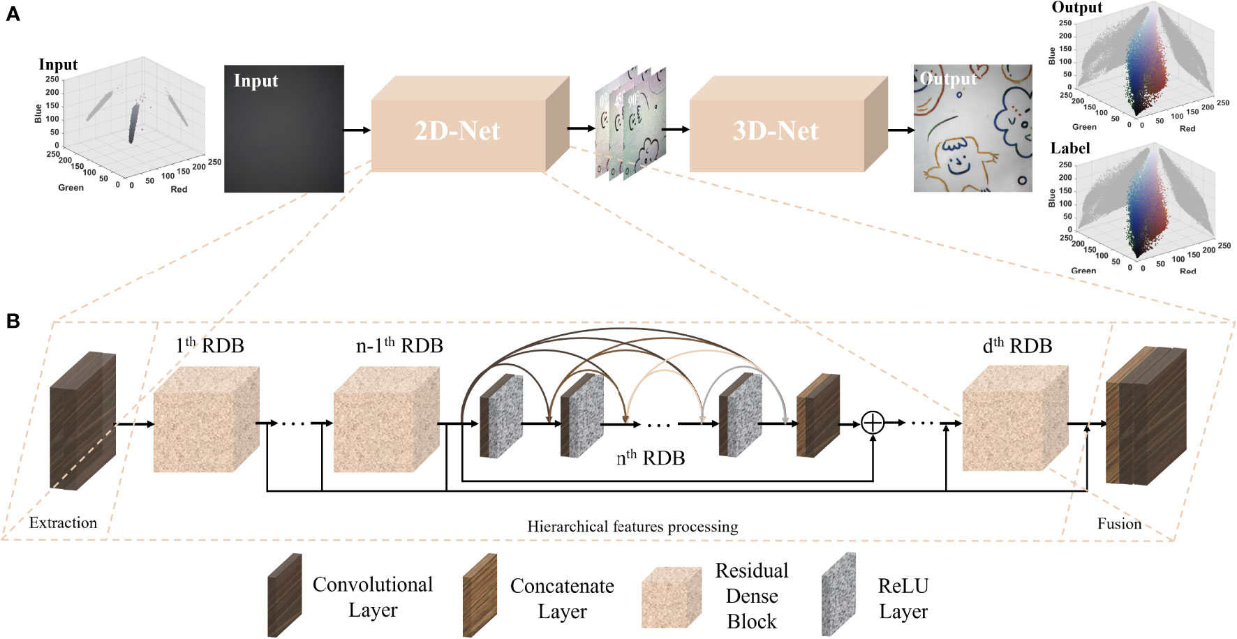
Figure 1 Network structure of UCRNet. (A) Overall model frame and 3D-RGB color models for input and output (B) Details of network structure.
The left and right side of Figure 1A shows the 3D RGB pixels spatial distributions of the input, output and label image, respectively. This figure represents the gray value of each pixel in a three-dimensional coordinate system with red, green, and blue as the coordinate axis. Each point’s color denotes its true color in the related images. Besides, we also draw the projection on the R (red)-B (blue) and B (blue)-G (green) plane. In fact, 1) the more color the clearer the images, as the input low-quality images always perform a single color, e.g., the gray. 2) the more scattered the pixels clearer the images as the inputs are compressed into a narrow pixel space. Besides, we may observe that the restored image’s point distribution of the 3D RGB pixels is more scattered and is close to that of the label image. From Figure 1B (i.e., in the proposed network), we first use two convolutional layers to extract shallow features from the input image (i.e., the raw images captured by the DoFP polarization camera), which is then sent into the followed eight residual dense blocks (Zhang et al., 2018) (RDBs) to extract hierarchical features. After a global features fusion operation including one concatenate layer and two convolutional layers. All the above steps use 2D convolution kernels and are combined as the first step (or the first sub-network) of the UCRNet, named 2D-Net. It can be seen in Figure 1A that the output features of the 2D-Net are images with different polarization angles. Subsequently, the output features are thrown into the following sub-network (i.e., 3D-Net), in which all the kernels are the 3D type. The output of the whole network is intensity image S0, and all the other structures and parameter designs are similar to the former 2D-Net. The detailed settings of the 3D-Net are listed in Table 1, where P and P0 are channels of features that should be determined before training. P is also called the growth rate of the residual dense blocks, and P × k is the input channel of the kth Conv-ReLU layer. Besides, the number of residual dense blocks in the 3D-Net is 4, and C is the total number of the Conv-ReLU layer in a single residual dense block. represents the hierarchical features from the preceding residual dense blocks, and F denotes the fusion operation. Eq. (5) can express the output image.
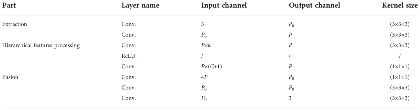
Table 1 Parameters of the 3D-Net.
Loss function
To guide the training, the designed loss functions include two types, i.e., the polarization loss and perceptual loss. Eq. (6) gives the polarization loss.
where Lout denotes the polarization loss for the final output and N means the scale of the training dataset. indicates the ith reconstructed polarization image corresponded to the polarization angle (i.e., θ ) of 0, 45, or 90 degrees is as the ith corresponding label image. The perceptual loss (Johnson et al., 2016) could be expressed as:
where C, W and H are the images’ channel, width, and height, respectively. ϕj is the jth layer of the pre-trained VGG-16 network on the ImageNet dataset (He et al., 2015). and respectively represent the output S0 and label S0 images, calculated as yc(0°)+yc(90°) . We compute the perceptual loss at layer relu1_2 of the VGG-16 pretrained network. By comparing the features of reconstructed and labeled images, we could take full advantage of the image feature extraction accuracy from networks pre-trained on enormous-scale datasets. Finally, Lsum in the following Eq. (8) denotes the summation of loss functions; λ1 andλ2 are the weights of polarization loss in Eq. (6) and perceptual loss in Eq. (7).
where λ1=Lout/Lout+Lper and λ2=Lper/Lout+Lper .
Training model details
The dataset includes 130 paired images collected and pre-processed under scattering media of full cream milk; 100 pairs were used as the training dataset, and the rest were divided into the validation dataset (15 pairs) and the test dataset (15 pairs). To expand the scale of the dataset and improve the training performance, the dataset is cropped to 64×64 pixels in the stride of 32 pixels in horizontal and vertical directions. As such, the scale of the training dataset reaches more than one hundred thousand images. Before the training, all the input images were normalized to [0,1], and each layer’s weights were initialized using the initialization method in ref (He et al., 2015). We use Pytorch as the deep learning framework on the Nvidia RTX2080Ti GPU, and the initial learning rate is e-4 and decays by a factor of 0.6 every ten epochs. We trained the network for 60 epochs using the Adam optimizer with a mini-batch size of 32.
Experiment
Dataset acquisition
Figure 2 presents the experimental setup for polarimetric imaging under turbid water, and all the image pairs in the dataset are captured by this setup. In this setup, the polarization state generator (PSG) is to produce linearly polarized light via a white broad-spectrum LED light source. The targeted object is placed in a water tank made of polymethyl methacrylate (PMMA) in size of 65 × 26 × 26 cm3. The imaging device is a chromatic division of focal plane (DoFP) polarization camera (Lucid-PHX050S) with a pixel size of 2048 × 2448 × 3. As shown in Figure 2, each macro super-pixel of the chromatic DoFP polarization camera consists of four micro super-pixels, i.e., two for green (G), one for red (R), and one for blue channels (B); each micro color super-pixel further consists of four pixels, each of which has a micro wire-grid polarizer orientated at 0°, 45°, 90°, and 135°, and the related intensity images are denoted as , , and , respectively, where c denotes the three color channels, i.e., R, G, and B. In practice, the circularly polarized light could perform better for the imaging through scattering media (Lewis et al., 1999; Xu and Alfano, 2005); yet the related optical system is more complex, and the data collection may become time-consuming. Based on that, we choose the chromatic DoFP polarization camera for the data acquisition.

Figure 2 Simulation diagram of the experimental setup for dataset acquisition. The scattering medium shown in the simulation diagram is full cream milk. The RGB-polarization pattern array of chromatic DoFP polarization camera by Lucid vision is at the top-left corner.
For the imaging experiments, we first added clear water to the tank and recorded the related image as the label for training. Subsequently, as the scattering properties of milk were confirmed to be relatively close to those of seawater by the long-term experiment (Dubreuil et al., 2013), we added the full cream milk into the clear water to generate the scattering media. Then, we record the images with degraded polarization information in the scattering environment after the milk is uniformly diffused. The scattering coefficient of the medium is influenced by the concentration of fat microspheres and casein molecules in the milk solution, which is equal to 3.00 mc (cm-1) for full cream milk, where mc represents the milk concentration in water (Piederrière et al., 2005). Notably, as the value of mc increases, the scattering coefficient becomes higher, and in this case, the polarization information of the object is further degraded. To ensure the reasonability of the experiments and the validity following verifications, we build the dataset in varying milk concentrations.
Visual comparisons
In this section, we perform imaging experiments to verify the effectiveness of the proposed network. Figure 3 first presents the raw images of two example scenes in dense turbid water. From Figure 3A, we may observe that most details are annihilated by the backscattered light, from which the color information cannot be distinguished. Besides, Figure 3B presents the related ground truths (GTs). The restored images by the proposed method are proposed in Figure 3C. From the results, we can see that all the details are well-addressed and the color information is significantly similar to GTs.
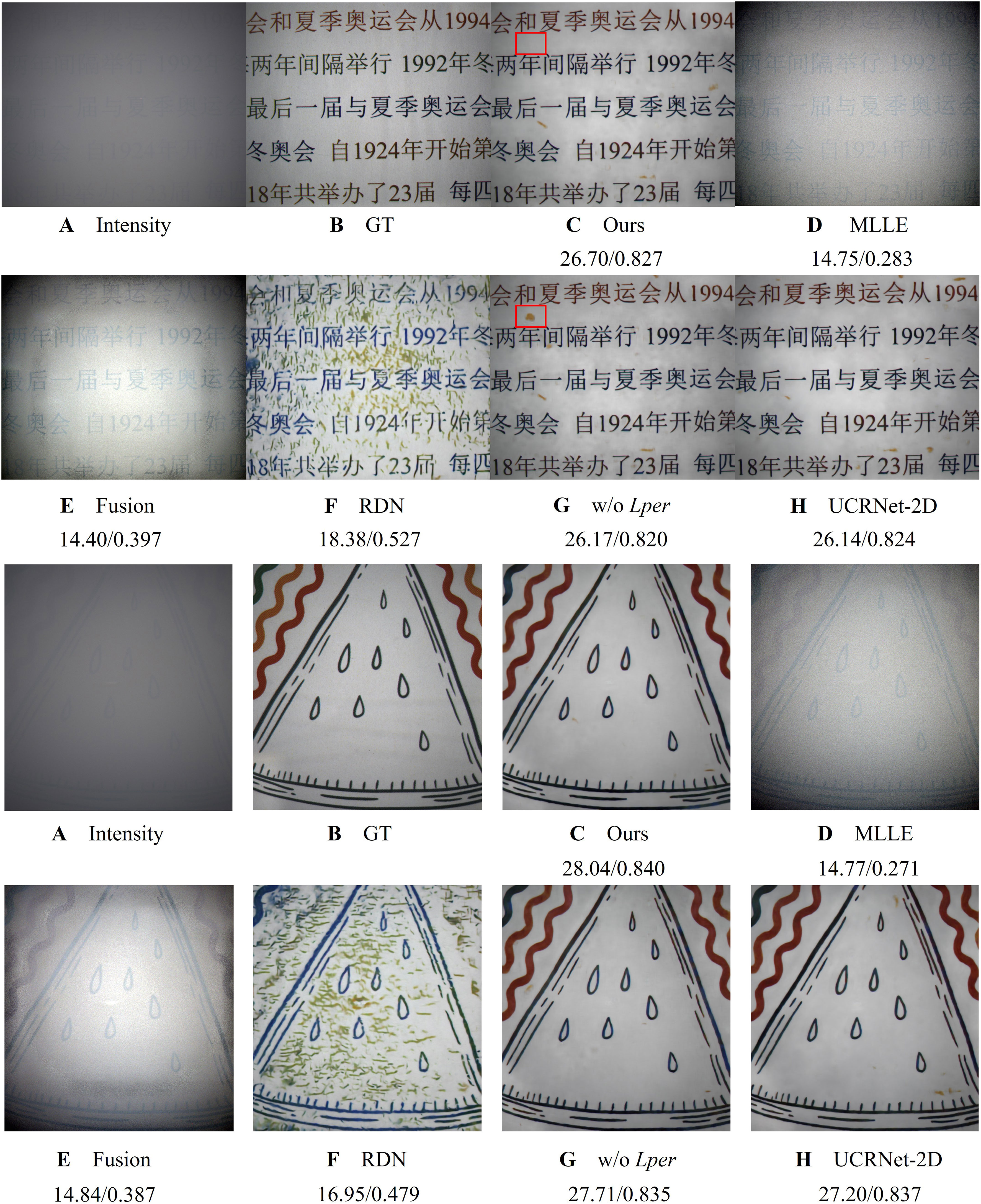
Figure 3 Results of the visual comparison. Two evaluation metrics below the image represent PSNR (dB) and SSIM respectively. (A) Intensity; (B) GT; Results by (C) Proposed method, (D) MLLE (E) Fusion, (F) RDN, (G) w/o Lper, and (H) UCRNet-2D. (1) and (2) are represented two samples in the test set.
To further verify the proposed method, we also present the restored images by some representative works, i.e., a fusion algorithm (Ancuti et al., 2012) proposed by Cosmin Ancuti et al., MLLE (Zhang et al., 2022), and RDN-Net (Hu et al., 2020). The Fusion method fuses several images using different enhanced method through Laplace’s pyramid to complement each other’s strengths. The MLLE method uses the grayscale world assumption as a criterion to achieve the effect of color compensation through several iterations. It is worth pointing out that the Fusion method is influenced by the active light source, and the halo affects the recovery image qualification, as shown in Figure 3E. The common problem of these digital image processing-based recovery methods is that the backscattered light scattered by the scattering medium is not well suppressed. As a result, the images seem still “hazy”. As shown in Figure 3F, this method greatly improves the image contrast but suffers from severe color distortion. In addition, we use two representative metrics, i.e., the peak of signal to noise ratio (PSNR) and structural similarity (SSIM), to quantificationally evaluate the final performance. The comparison values (PSNR/SSIM) are listed under the corresponding images in Figure 3. The value of the method based on digital image processing is significantly lower than that of the proposed method.
To verify that adding perceptual loss can improve the quality of the restored image, we remove the perceptual loss and the rest of the training details remain unchanged. Without (w/o) perceptual loss in Figure 3G, the result obtained has some yellow artifacts (framed by the red rectangle) in different positions of the first image. In addition, we can also observe the effect of over-enhancement (a broad edge along the pattern lines) on the boundaries of the second image. For the UCRNet-2D method, we change the 3D-Net of the proposed method to a 2D-Net. The parameters of a 3-D convolution kernel are approximately three times that of a 2-D convolution kernel. To ensure the consistency of the overall network parameters, twelve dense residual blocks are used in the UCRNet-2D method. The recovered images are close to the proposed method, but with a certain degree of artifacts. The superiority of the proposed method of recovery considering polarization guidance is demonstrated by comparison with UCRNet-2D method. Besides, Figure 4 shows an additional example to compare the performance in avoiding artifacts for the UCRNet-2D and -3D methods. From this figure, we may find that, compared with the UCRNet-3D’s result, there are significant artifacts in that of UCRNet-2D, as shown in the red rectangles.
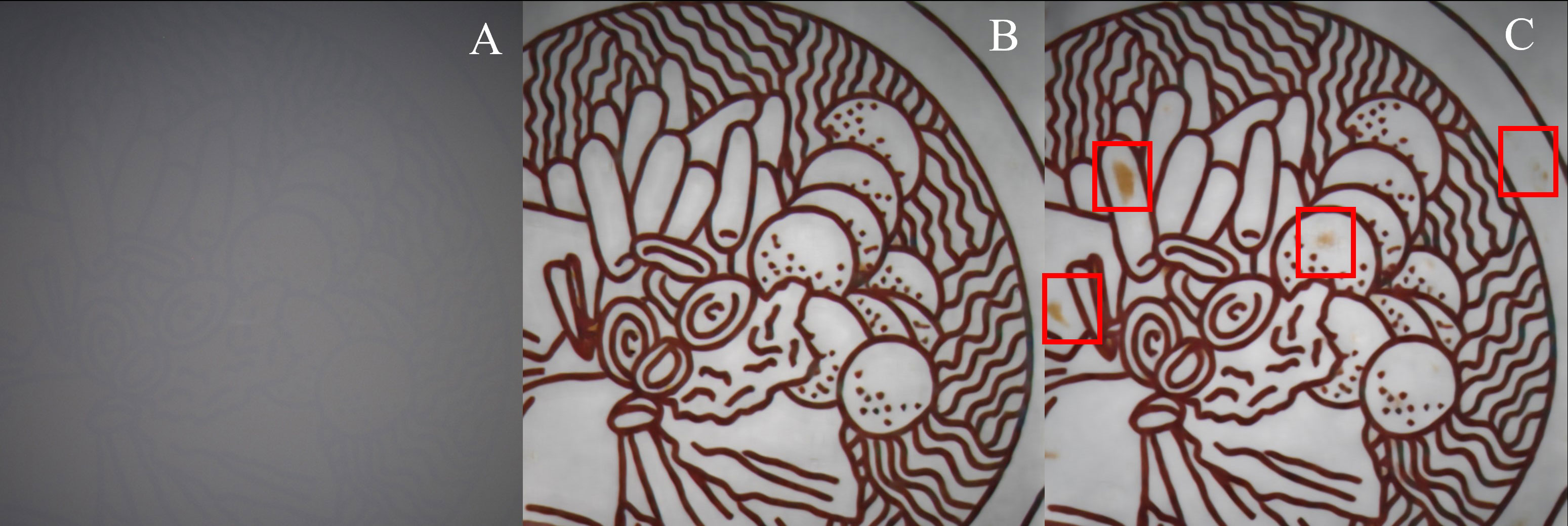
Figure 4 Results of the visual comparison. (A) Intensity image (B) Proposed method and (C) Result obtained by UCRNet-2D.
Furthermore, we also calculate the PSNR, SSIM, ZNCC (Zero-normalized cross-correlation) and UICM (underwater image colorfulness measure) average values on the test set, as shown in the Table 2. In terms of the average PSNR value, the proposed method shows a better performance than other representative methods in Figure 3. This conclusion agrees with the results of the visual comparisons in Figures 3D–F, proving the superiority of the proposed method. Compared with w/o Lper and ours, the value is improved by 0.35dB, which further demonstrates the necessity of well-designed loss in the proposed method. As for the UCRNet-2D, the average value of the proposed method is increased by 0.12dB. Consequently, we can conclude that the polarization-guided network is significant in improving the network performance. ZNCC is for evaluating the cross-correlation between two images and the higher the value, the more correlated the two images are. Our proposed method performs best on the ZNCC evaluation metric. UICM is an evaluation metric that measures the deviation of the different color channels. Since the backscattered light of the images processed by MLLE and Fusion methods is not completely removed, the UICM evaluation metric is falsely high. The value of UICM also confirm our method features the better restored color information.
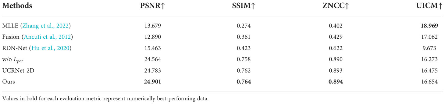
Table 2 Quantitative comparisons of different methods.
We also perform the proposed method on different turbidity and the results are shown in Figure 5. The corresponding PSNR/SSIM values are also presented under the restored results. From the Figure 5, we may observe that the proposed method can well restore the hazy images in both low and high turbidity levels, verifying the universality of our method.

Figure 5 Results on low turbidity and high turbidity. Two evaluation metrics below the image represent PSNR (dB) and SSIM respectively.
Moreover, we extend the proposed method to other scattering media-real foggy environments. The dataset we used is Polarized Foggy Cityscapes-DBF dataset-Zurich in ref (Zhou et al., 2021). This dataset provides depth and foggy maps corresponding to different scattering coefficients, semantic segmentation maps, and intensity images of urban streets. Using the depth map and the corresponding scattering coefficient, the scattering length distribution map that can simulate the effect of haze gradually deepening from near to far can be obtained. The polarization characteristics are related to the object’s material, taking advantage of semantic segmentation images to assign equal degrees of polarization value to objects with the same semantic information is more suitable for the natural environment. Paired images of different polarization directions are obtained using Malus law. Figure 6 presents the related extension results, which includes the comparison of intensity, GT, our restoration images as well as the calculated PSNR/SSIM values. From Figure 6, we may conclude that the trained model proposed in Section 2.1 is fine-tuned in the Zurich. The image details are well observed in the restored image, such as the bus stop (in the orange rectangle) nearby the trees in Figure 6A and the distant views (in the red rectangle) in Figure 6B.
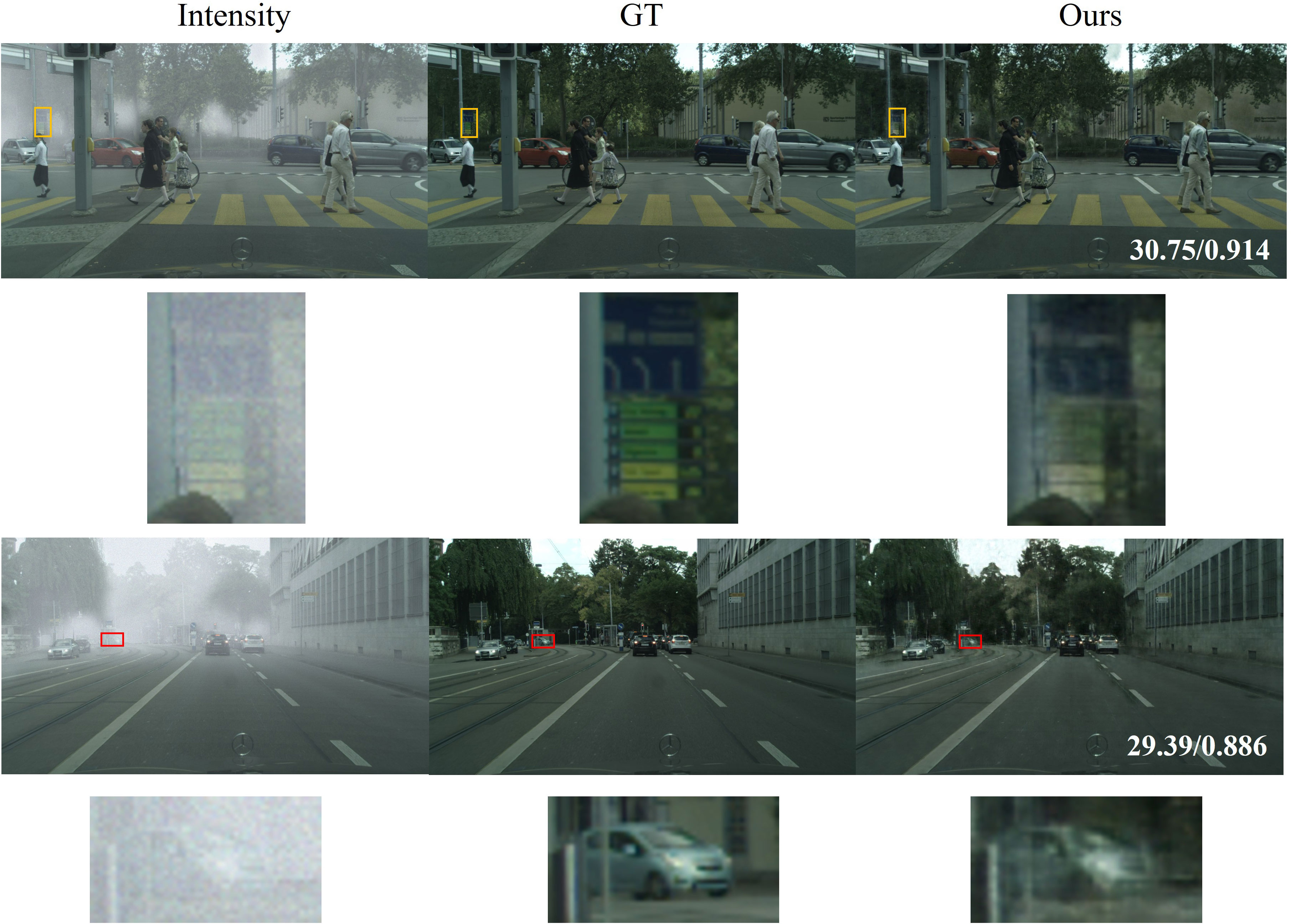
Figure 6 Visual de-scattering effects on Polarized Foggy Cityscapes-DBF dataset-Zurich. The numbers on the bottom-right corner of each image refer to its PSNR (dB) and SSIM. The bottom of each image represents the corresponding area in the rectangle frame. (1) and (2) are represented as two samples in the test set.
Furthermore, Table 3. compares the imaging performance between our method and the selected the typical polarimetric methods, i.e., polarization difference imaging models proposed by Schechner (Skinner and Johnson-Roberson, 2017), and three non-polarimetric methods, including the (1) dark channel prior-based method (DCP) (He et al., 2010), (2) fusion method (Ancuti et al., 2012), and (3) an open dehazing platform developed by Baidu (Li et al., 2017). From the Table 3, one may find that our method achieved the highest values in most metrics, including PSNR, SSIM, ZNCC and NIQE. These compared methods are not capable of dealing with unevenly distributed haze environment images. Compared with the raw image and Baidu’s results, our method has effectively improved the image’s PSNR values by 10.9dB and 10.8dB, respectively. In conclusion, both subjective visual effects and objective evaluation metrics prove that this method could be extended to city foggy scattering environments. We must note that the recovery results contain more noise than GTs; this is because the original intensity images are noisy. Besides, the scattering density of the foggy dataset is also lower than that in the turbid water we designed. The two problems can be further addressed by choosing a high-scattering but high-quality dataset, which is a promising work in future.
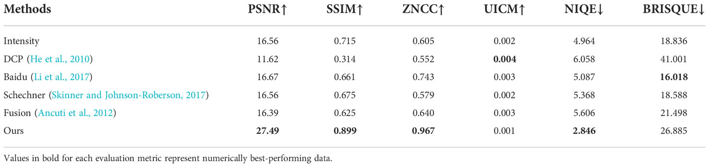
Table 3 Average evaluation metrics on the test set.
Conclusion
To our knowledge, this is the first work to introduce polarization information into a network to achieve the de-scattering effect on color imaging. We successfully constructed a polarization-guided network, which further improved the recovery effect of the network. We also show that the quality of restored images can be enhanced by introducing a well-designed loss function and the capability of the proposed method in different turbidity. Comprehensive experimental results confirm that the proposed method outperforms other representative methods, including learning-based methods and digital image processing-based methods. Moreover, we demonstrate that the technique can be extended to the field of image dehazing in natural environments. Our solution may find important applications in object detection and clear vision under strong scattering conditions (e.g., dense fog, deep-sea, and biological field) by adjusting the designs of loss functions and network structures according to the special applications.
Data availability statement
The raw data supporting the conclusions of this article will be made available by the authors, without undue reservation.
Author contributions
Conceptualization, XL, YH, and HH. Funding acquisition, HH. Methodology, XL, YH, and HH. Resources, XL and YH. Supervision, XL and HH. Validation, YH and XL. Visualization, XL and YH. Writing – original draft, HH, YH, and XL. Writing – review & editing, XL, YH, LJ, LC, TL, and JZ. All authors contributed to the article and approved the submitted version.
Funding
Guangxi Special Fund Project for Innovation-Driven Development (No. GuikeAA21077008) and National Natural Science Foundation of China (62075161, 62205243).
Conflict of interest
The authors declare that the research was conducted in the absence of any commercial or financial relationships that could be construed as a potential conflict of interest.
Publisher’s note
All claims expressed in this article are solely those of the authors and do not necessarily represent those of their affiliated organizations, or those of the publisher, the editors and the reviewers. Any product that may be evaluated in this article, or claim that may be made by its manufacturer, is not guaranteed or endorsed by the publisher.
References
Ancuti C., Ancuti C. O., Haber T., Bekaert P. (2012). “Enhancing underwater images and videos by fusion,” in Proc. IEEE Conf. Comput. Vision Pattern Recognition. (Washington, DC,: IEEE), 81–88.
Carreira J., Zisserman A. (2017). “Quo vadis, action recognition? a new model and the kinetics dataset,” in proceedings of the IEEE Conference on Computer Vision and Pattern Recognition. 6299–6308.
Ding X., Wang Y., Fu X. (2022). Multi-polarization fusion generative adversarial networks for clear underwater imaging. Optics Lasers Eng. 152, 106971. doi: 10.1016/j.optlaseng.2022.106971
Dubreuil M., Delrot P., Leonard I., Alfalou A., Brosseau C., Dogariu A. (2013). Exploring underwater target detection by imaging polarimetry and correlation techniques. Appl. Optics 52 (5), 997–1005. doi: 10.1364/AO.52.000997
Fattal R. (2014). Dehazing using color-lines. ACM Trans. Graphics (TOG) 34 (1), 1–14. doi: 10.1145/2651362
He K., Sun J., Tang X. (2010). Single image haze removal using dark channel prior. IEEE Trans. Pattern Anal. Mach. Intell. 33 (12), 2341–2353. doi: 10.1109/TPAMI.2010.168
He K., Zhang X., Ren S., Sun J. (2015). “Delving deep into rectifiers: Surpassing human-level performance on imagenet classification,” in Proceedings of the IEEE International Conference on Computer Vision. 1026–1034.
Hu H., Han Y., Li X., Jiang L., Che L., Liu T., et al. (2022). Physics-informed neural network for polarimetric underwater imaging. Optics Express 30 (13), 22512–22522. doi: 10.1364/OE.461074
Hu H., Lin Y., Li X., Qi P., Liu T. (2020). IPLNet: a neural network for intensity-polarization imaging in low light. Optics Lett. 45 (22), 6162–6165. doi: 10.1364/OL.409673
Hu H., Qi P., Li X., Cheng Z., Liu T. (2021). Underwater imaging enhancement based on a polarization filter and histogram attenuation prior. J. Phys. D: Appl. Phys. 54 (17), 175102. doi: 10.1088/1361-6463/abdc93
Hu H., Zhang Y., Li X., Lin Y., Cheng Z., Liu T. (2020). “Polarimetric underwater image recovery via deep learning,” in Optics and lasers in engineering, vol. 133. (Berkely, CA: Optics and Lasers in Engineering (Elsevier)), 106152.
Hu H., Zhao L., Li X., Wang H., Liu T. (2018). Underwater image recovery under the nonuniform optical field based on polarimetric imaging. IEEE Photonics J. 10 (1), 1–9. doi: 10.1109/JPHOT.2018.2791517
Johnson J., Alahi A., Fei-Fei L. (2016). “Perceptual losses for real-time style transfer and super-resolution,” in European Conference on computer vision New York, NY, USA: European conference on computer vision (Springer), pp.694–pp.711.
Lewis G. D., Jordan D. L., Roberts P. J. (1999). Backscattering target detection in a turbid medium by polarization discrimination. Appl. Optics 38 (18), 3937–3944. doi: 10.1364/AO.38.003937
Liang J., Ren L., Ju H., Zhang W., Qu E. (2015). Polarimetric dehazing method for dense haze removal based on distribution analysis of angle of polarization. Optics Express 23 (20), 26146–26157. doi: 10.1364/OE.23.026146
Liang J., Ren L., Liang R. (2021). Low-pass filtering based polarimetric dehazing method for dense haze removal. Optics Express 29 (18), 28178–28189. doi: 10.1364/OE.427629
Li C., Guo J., Guo C. (2018). Emerging from water: Underwater image color correction based on weakly supervised color transfer. IEEE Signal Process. Lett. 25 (3), 323–327. doi: 10.1109/LSP.2018.2792050
Li C., Guo C., Ren W., Cong R., Hou J., Kwong S., et al. (2019). An underwater image enhancement benchmark dataset and beyond. IEEE Trans. Image Process. 29, 4376–4389. doi: 10.1109/TIP.2019.2955241
Li X., Hu H., Zhao L., Wang H., Yu Y., Wu L., et al. (2018). Polarimetric image recovery method combining histogram stretching for underwater imaging. Sci. Rep. 8 (1), 1–10. doi: 10.1038/s41598-018-30566-8
Li X., Li H., Lin Y., Guo J., Yang J., Yue H., et al. (2020). Learning-based denoising for polarimetric images. Optics Express 28 (11), 16309–16321. doi: 10.1364/OE.391017
Li B., Peng X., Wang Z., Xu J., Feng D. (2017). “Aod-net: All-in-one dehazing network,” in Proceedings of the IEEE international conference on computer vision. 4770–4778.
Liu F., Wei Y., Han P., Yang K., Bai L., Shao X. (2019). Polarization-based exploration for clear underwater vision in natural illumination. Optics Express 27 (3), 3629–3641. doi: 10.1364/OE.27.003629
Liu H., Zhang Y., Cheng Z., Zhai J., Hu H. (2022). Attention-based neural network for polarimetric image denoising. Optics Lett. 47 (11), 2726–2729. doi: 10.1364/OL.458514
Li X., Xu J., Zhang L., Hu H., Chen S. C. (2022). Underwater image restoration via stokes decomposition. Optics Lett. 47 (11), 2854–2857. doi: 10.1364/OL.457964
Nothdurft R. E., Yao G. (2006). Effects of turbid media optical properties on object visibility in subsurface polarization imaging. Appl. optics 45 (22), 5532–5541. doi: 10.1364/AO.45.005532
Novikova T., Bénière A., Goudail F., De Martino A. (2009). Sources of possible artefacts in the contrast evaluation for the backscattering polarimetric images of different targets in turbid medium. Optics Express 17 (26), 23851–23860. doi: 10.1364/OE.17.023851
Novikova T., Bénière A., Goudail F., De Martino A. (2010). “Contrast evaluation of the polarimetric images of different targets in turbid medium: Possible sources of systematic errors,” in Polarization: Measurement, analysis, and remote sensing IX, vol. 7672. (Bellingham, WA, USA: SPIE), 189–197.
Piederrière Y., Boulvert F., Cariou J., Le Jeune B., Guern Y., Le Brun G. (2005). Backscattered speckle size as a function of polarization: Influence of particle-size and-concentration. Optics Express 13 (13), 5030–5039. doi: 10.1364/OPEX.13.005030
Qi P., Li X., Han Y., Zhang L., Xu J., Cheng Z., et al. (2022). U2R-pGAN: Unpaired underwater-image recovery with polarimetric generative adversarial network. Optics Lasers Eng. 157, 107112. doi: 10.1016/j.optlaseng.2022.107112
Schechner Y. Y., Karpel N. (2004). “Clear underwater vision,” in Proceedings of the IEEE Conference on Computer Vision and Pattern Recognition. I–I.
Schechner Y. Y., Narasimhan S. G., Nayar S. K. (2003). Polarization-based vision through haze. Appl. Optics 42 (3), 511–525. doi: 10.1364/AO.42.000511
Seeram E. (2019). “Digital image processing concepts,” in Digital radiography (Singapore: Springer), (pp.21–(pp39).
Shao H., He Y., Shao Y., Ma H. (2006). “Contrast enhancement subsurface optical imaging with different incident polarization states,” in Fourth international conference on photonics and imaging in biology and medicine, vol. 6047. (Bellingham, WA, USA: SPIE), 226–231.
Skinner K. A., Johnson-Roberson M. (2017). “Underwater image dehazing with a light field camera,” in Proceedings of the IEEE conference on computer vision and pattern recognition workshops. 62–69.
Sun Y., Zhang J., Liang R. (2021). Color polarization demosaicking by a convolutional neural network. Optics Lett. 46 (17), 4338–4341. doi: 10.1364/OL.431919
Varol G., Laptev I., Schmid C. (2017). Long-term temporal convolutions for action recognition. IEEE Trans. Pattern Anal. Mach. Intell. 40 (6), 1510–1517. doi: 10.1109/TPAMI.2017.2712608
Wei Y., Han P., Liu F., Shao X. (2021). Enhancement of underwater vision by fully exploiting the polarization information from the stokes vector. Optics Express 29 (14), 22275–22287. doi: 10.1364/OE.433072
Xu M., Alfano R. R. (2005). Circular polarization memory of light. Phys. Rev. E 72 (6), 065601. doi: 10.1103/PhysRevE.72.065601
Zhang Y., Tian Y., Kong Y., Zhong B., Fu Y. (2018). Residual dense network for image super-resolution. In Proc. IEEE Conf. Comput. Vision Pattern Recognition 133, 2472–2481. doi: 10.1109/CVPR.2018.00262
Zhang W., Zhuang P., Sun H. H., Li G., Kwong S., Li C. (2022). Underwater image enhancement via minimal color loss and locally adaptive contrast enhancement. IEEE Trans. Image Process. 31, 3997–4010. doi: 10.1109/TIP.2022.3177129
Keywords: Polarization, polarimetric imaging, scattering media, imaging recovery, physical imaging
Citation: Hu H, Huang Y, Li X, Jiang L, Che L, Liu T and Zhai J (2022) UCRNet: Underwater color image restoration via a polarization-guided convolutional neural network. Front. Mar. Sci. 9:1031549. doi: 10.3389/fmars.2022.1031549
Received: 30 August 2022; Accepted: 10 November 2022;
Published: 28 November 2022.
Edited by:
Ran Liao, Tsinghua University, ChinaReviewed by:
Tatiana Novikova, École Polytechnique, FranceLina Zhou, Hong Kong Polytechnic University, Hong Kong SAR, China
Copyright © 2022 Hu, Huang, Li, Jiang, Che, Liu and Zhai. This is an open-access article distributed under the terms of the Creative Commons Attribution License (CC BY). The use, distribution or reproduction in other forums is permitted, provided the original author(s) and the copyright owner(s) are credited and that the original publication in this journal is cited, in accordance with accepted academic practice. No use, distribution or reproduction is permitted which does not comply with these terms.
*Correspondence: Xiaobo Li, lixiaobo@tju.edu.cn