Research and analysis of electromagnetic interference of a motor drive control system based on PMSM with SiC MOSFET for new energy electric vehicles
 Chi Zhang
 Jasronita Jasni
 Mohd Amran Mohd Radzi1,2
  Norhafiz Azis
 Xiangming He
- 1Department of Electrical and Electronic Engineering, Faculty of Engineering, Universiti Putra Malaysia, Serdang, Selangor, Malaysia
- 2Power and Energy Research Centre (ALPER), Faculty of Engineering, Universiti Putra Malaysia, Serdang, Selangor, Malaysia
- 3Infineon Technologies China Co., Ltd., Xi’an, China
- 4ABB Beijing Drive Systems Co., Ltd., Beijing, China
- 5Institute of Nuclear and New Energy Technology, Tsinghua University, Beijing, China
Sustainable development in the 21st century faces significant challenges due to finite reserves of fossil fuels and environmental pollution. In the context of new energy electric vehicles (NEEVs), the wide-bandgap semiconductor known as the silicon carbide–metal oxide–semiconductor field-effect transistor (SiC MOSFET) and the permanent magnet synchronous motor (PMSM) have emerged as advantageous sources. However, the use of these components gives rise to electromagnetic interference (EMI) issues, which impede the achievement of electromagnetic compatibility (EMC) standards in the motor drive control system. This paper aims to elucidate the generation mechanism, propagation path, and test infrastructure of EMI. Furthermore, it proposes a system-level conducted EMI equivalent circuit model for the motor drive control system, encompassing the power battery pack, busbar cable, LISN, three-phase inverter, and PMSM. Building upon this foundation, the principles for suppressing and optimizing EMI noise are discussed. The paper concludes with the validation of simulations and experimental results, which demonstrate the effectiveness of the proposed approach. It is anticipated that professionals with an interest in the field of EMI/EMC will find this paper to be of both theoretical and practical importance.
1 Introduction
Against the background of the traditional fossil energy shortage crisis and sustainable green development path (Ranjan Kumar and Kumar, 2020; Kalair et al., 2021; Li et al., 2022), it is encouraging that new energy electric vehicles (NEEVs) have been rapidly popularized worldwide due to their inherent advantages of zero harmful gas emissions, low energy consumption and non-pollution, high efficiency, and the use of more environmentally friendly electric energy as power sources (Buenger and Michalski, 2018; Mihet-Popa and Saponara, 2018; Hossain et al., 2022a; Cheok et al., 2022). Compared with the conventional internal combustion engine (ICE), NEEVs have more electronic and electrical equipment, including a power battery pack, inverters, traction electromotors, controllers, and a busbar cable, as shown in Figure 1 (Kene et al., 2021; Hossain et al., 2022b).
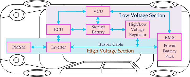
FIGURE 1. Main electrical components of NEEVs.
Obviously, the battery management systems (BMSs) communicate with the vehicle control unit (VCU) to adjust the high direct voltage and current from the power battery pack. The VCU establishes a bidirectional data interchange channel through the controller area network (CAN) bus (Tran et al., 2020; Zhao et al., 2022), and then the electronic control unit (ECU) sends a pulse-width modulation (PWM) signal to drive the power switches, the silicon carbide–metal oxide–semiconductor field-effect transistor (SiC MOSFET) in the inverter, to turn on and off, thereby achieving permanent magnet synchronous motor (PMSM) speed control (Yang et al., 2020; Liu et al., 2021; Barroso et al., 2022).
In actual operation, these high-voltage, high-current, and high-power electrical components produce electromagnetic interference (EMI). To make matters even worse, the on-board electronic devices with high sensitivity, such as BMS, VCU, and ECU, are more susceptible to EMI, which is directly related to the safety, reliability, and comfort of NEEVs (López et al., 2019). Therefore, the internal electromagnetic environment is more complex, and electromagnetic compatibility (EMC) is also facing greater challenges and opportunities in NEEVs, which attracts more attention and requires further discussion (Ma et al., 2018; Hu et al., 2021).
In recent years, third-generation semiconductor materials have shown significant advantages in bandgap, electric breakdown field, saturated electron drift velocity, thermal conductivity, and radiation resistance, which further meet the new requirements of high temperature, high power, high voltage, and high frequency in the field of modern electronic technology (Van Do et al., 2021). SiC MOSFETs have higher switching speed, smaller losses, and high temperature working tolerance, which can reduce the size and volume of passive components (such as heat sinks, inductors, and capacitors) to achieve higher power density and efficiency (Alcázar-García and José Luis Romeral, 2022; Robles et al., 2022). Therefore, SiC MOSFETs have been widely predicted to be superior to Si IGBTs as power switch tube devices, which provides a promising solution for the motor drive control system in NEEVs (Gurpinar et al., 2018; Zhu et al., 2018; Wu et al., 2022).
It is particularly concerning that the high-speed switching actions of the SiC MOSFET can interact with parasitic resistors, capacitors, and inductors from the system circuit, resulting in a surge in the voltage and ringing effect, which can lead to undesired and still worrisome EMI problems. In previous studies (Oswald et al., 2014; Jia et al., 2020), the major high-frequency EMI source of the SiC MOSFET is the changes from high voltage and current (dv/dt and di/dt) conversion; SiC MOSFETs produce a higher-spectrum amplitude than Si IGBTs in the frequency range of 2–50 MHz. EMI has great potential to cause performance degradation, an increase in failure, and shorten the service life of NEEVs (Zhang and Wang, 2021). This has brought attention to an important concern: electromagnetic compatibility (EMC). In 1833, the English physicist and chemist Faraday (1791–1867) discovered electromagnetic induction. The concept of EMC originated in the 19th century. EMC performance refers to the abilities of a device or system to function properly in its electromagnetic environment, and it also would not cause unsustainable electromagnetic disturbance to anything in the environment (Ding et al., 2021). In short, most EMI in the motor drive control system comes from
a) High dv/dt and di/dt;
b) Change in impedance characteristics of resistors, capacitors, and inductors in the high-frequency range;
c) PWM contains abundant voltage and current switching harmonics.
EMC testing has certain standards, as shown in Figure 2. Regardless of whether people develop 5G products, automotive equipment, military equipment, or something as simple as an ordinary table lamp, the device must meet the requirements set by the standardization organizations shown in Table 1 such as the International Electrotechnical Commission (IEC), International Special Committee on Radio Interference (CISPR), International Standardization Organization (ISO), Institute of Electrical and Electronic Engineers (IEEE), Comite Europeen de Normalisation Electrotechnique (CENELEC), European Telecommunications Standards Institute (ETSI), Federal Communications Commission (FCC), American National Standards Institute (ANSI), Radio Technical Commission for Aeronautics (RTCA), or the Military Standards (MIL-STD) committee.
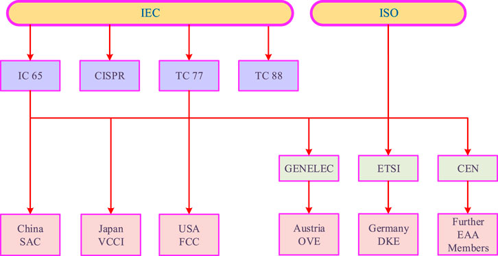
FIGURE 2. EMC standardization organizations committee.

TABLE 1. Commercial EMC standards.
Serious EMI problems of the motor drive control system are characterized by high noise amplitude, complex coupling, and multiple paths, which are closely related to working conditions (Wang et al., 2021). EMI can be divided into conducted EMI and radiated EMI, and common mode (CM) interference and differential mode (DM) interference are two differential conducted forms of the conducted EMI, according to their own propagation path and coupling channel (Jia et al., 2021; Rifan et al., 2021). In addition, the generated CM and DM interference will form a small loop or wire antenna through the busbar cable, which can result in radiated EMI to other systems or devices (Didat et al., 2020). However, without EMC design and correction, the EMI can hardly meet the standard limit requirements (150 kHz–30 MHz in CISPR 25). Therefore, the suppression of EMI from the motor drive control system has been increasingly receiving attention from both academia and the industry (Ozaki et al., 2017; He et al., 2020).
Currently, research on the EMI and EMC of motor drive control systems focuses on three main areas: mechanism analysis, modeling, and suppression measures (Gong and Ferreira, 2010; Hu et al., 2018; Liu et al., 2019; Rao et al., 2021; Safayet and Islam, 2021; Zhai et al., 2021; Kumar and Jayaraman, 2022; Wang et al., 2022). Hu et al. (2018) introduced EMC problems and investigated the EMI mechanism of motor driving systems, charging systems, and other low-voltage systems. The EMI of the power components in an NEEV motor drive control system is given in Rao et al. (2021), including its propagation path and the method of interference measurement. Gong and Ferreira (2010) proposed a general device-based CM model that can describe the propagating mechanism in the system. Wang et al. (2022) proposed a high-frequency model to predict the system-level conducted EMI. A conducted emission model with lumped and finite-element parameter circuit-based electromagnetic simulation is presented in Safayet and Islam (2021). Liu et al. (2019) described a complete equivalent circuit model, and CM conducted emissions can be predicted and evaluated during the design phase for performance optimization purposes. Kumar and Jayaraman (2022) presented three modified single-stage and multistage EMI filters to offer the same CM and DM attenuation performances for an SiC inverter switching at 200 kHz. Two EMI filter design methods for high-voltage DC ports of NEEV motor controllers are proposed in Zhai et al. (2021).
In this paper, different from existing papers, a system-level conducted EMI equivalent circuit model of the motor drive control system based on a PMSM with an SiC MOSFET for NEEVs has been proposed to research and analyze the noise of conducted EMI. Then, in order to meet EMC standards, the suppression and optimization measures were summarized. Finally, the simulation and experimental results were validated in the laboratory.
The structure of the paper is organized as follows: Section 1 provides an introduction; Section 2 provides the equivalent circuit models of the motor drive control system; Section 3 elaborates the EMI suppression and optimization measures; Section 4 provides the simulation and experimental results; and finally, the conclusions and future work are summarized accordingly in Section 5.
2 Conductive EMC mechanism of the motor drive control system
In the past, EMI modeling was considered difficult and impractical because it required detailed parameters that could not be predicted until the printed circuit board (PCB) layout was completed. Section 3 establishes and analyzes the EMI system-level equivalent circuit model, which follows the top–down process and can be changed with the project’s progress to improve fidelity.
2.1 Equivalent circuit models of power electronic components
The EMI of the motor drive control system is fundamentally caused by its own power electronics components. Therefore, it is necessary to establish an effective and accurate equivalent circuit model with electronic components such as a resistor, a capacitor, a busbar cable, a power battery pack, a SiC MOSFET, a PMSM, and PCB wiring.
2.1.1 Electric capacitor models
Figure 3 shows that capacitance C is the ideal capacitor and Rp is the insulation resistance corresponding to the direct leakage current. Heat dissipation within the plates, terminals, and all conducting parts is represented by Rs, and it is known as the equivalent series resistance (ESR). L stands for the total inductance of the leads and plates as the equivalent series inductance (ESL).
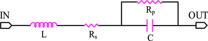
FIGURE 3. Equivalent circuit model of an electric capacitor.
2.1.2 Busbar cable
Busbar cables, found in power distribution systems, are distributed elements whose lengths may by far exceed the operating wavelength, as shown in Figure 4. They can be modeled as multi-conductor transmission lines, where many frequency-dependent characteristics, including per unit length parameters, skin and proximity effects, dielectric losses, and transmission line propagation, reflections, and delay, need to be appropriately taken into account.
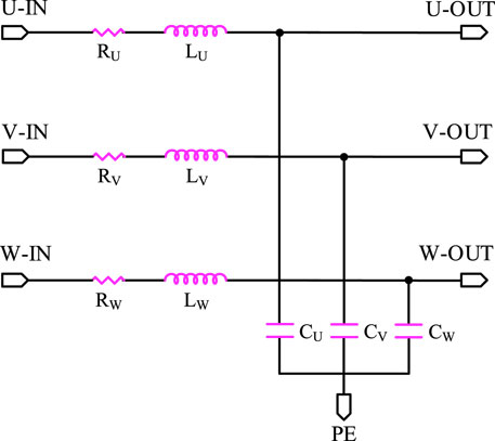
FIGURE 4. Equivalent circuit for modeling a long three-phase busbar cable.
Therefore, the main purpose of modeling the busbar cable is to determine the resistance
First, the resistance
where
Next, the inductance
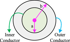
FIGURE 5. Busbar cable self-inductance diagram.
According to the transmission line theory, the internal self-inductance per meter
where
So the value of the self-inductance per meter of the cable L is
Lastly, the capacitance between the shielding layer and the unit length cable
where
2.1.3 Power battery pack
In the market, in order to extend the driving mileage of NEEVs, a large number of low-voltage single cells are required to be connected to a high-voltage power battery pack. The equivalent circuit model is shown in Figure 6.
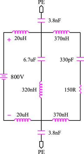
FIGURE 6. Equivalent circuit model of the power battery pack.
2.1.4 SiC MOSFET
For the SiC MOSFET, the parasitic capacitance and inductance need to be considered for more accurate modeling. As shown in Figure 7,
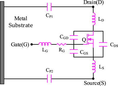
FIGURE 7. SiC MOSFET equivalent circuit model with parasitic parameters.
2.1.5 PMSM
The PMSM is one of the most complex electrical parts in the motor drive control system. It is impossible to know the whole parameter details in practice, and the physical modeling method of the motor is usually not applicable. The PMSM is a low-frequency induction device and modeled by a three-phase linear RLC circuit, as shown in Figure 8.
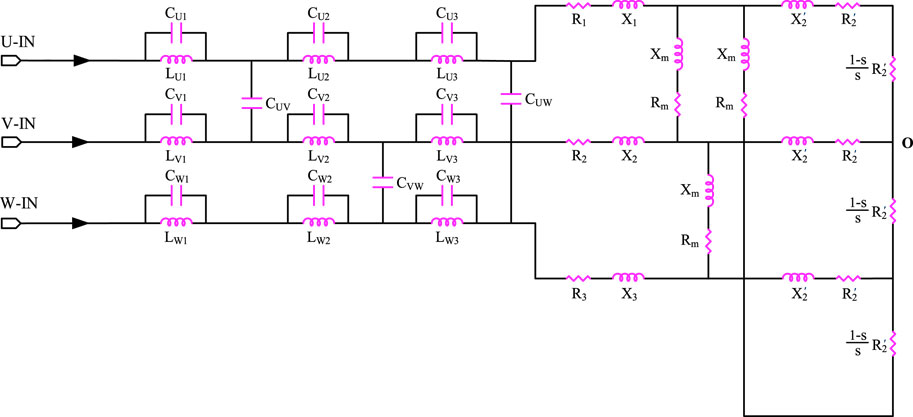
FIGURE 8. Coupled three-phase RLC equivalent circuit model of the PMSM.
2.1.6 PCB tracks
The influence of the PCB tracks’ interconnect design is sometimes overlooked in EMC research and analysis. When extracting the parasitic parameters of PCB tracks, only parasitic resistance and inductance are considered because the parasitic capacitance is very small. For example, PCB tracks L and N can be regarded as two conductors. The equivalent circuit model is shown in Figure 9, where
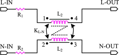
FIGURE 9. HF equivalent circuit model of the PCB tracks L and N.
Table 2 shows that with the increase in frequency, self-inductance and mutual inductance values hardly change, while resistance values change greatly and provide some useful experiences and lessons for an ultra-high frequency motor drive control system.
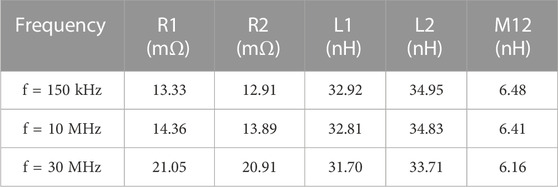
TABLE 2. HF parasitic parameters of PCB tracks L and N.
2.2 Equivalent circuit models of the motor drive control system
Figure 10 presents the system-level equivalent circuit models of the motor drive control system, including the power battery pack, LISN, three-phase inverter, busbar cable, and PMSM. The spectrum of the EMI source is distributed in the frequency range of 150 kHz–30 MHz. Therefore, the parasitic parameters must be considered to research and analyze the transmission path of the conducted EMI.
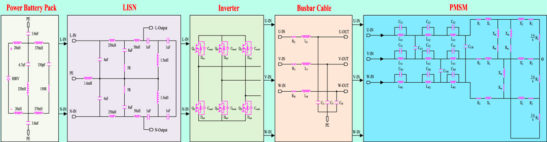
FIGURE 10. System-level equivalent circuit models of the motor drive control system.
3 Discussion of EMI suppression of the motor drive control system
Section 3 introduces the conducted EMI model of the motor drive control system in NEEVs to better understand how it generates and propagates paths and predicts noise levels. However, due to EMC standards, the conducted EMI needs to be limited. To improve the conducted EMI, it is usually necessary to consider three aspects: suppressing the interference source, optimizing the propagation path, and improving equipment immunity.
3.1 EMI suppression and optimization measures
Currently, regarding the motor drive control system, the specific measures mainly include electromagnetic shielding grounding, installation filters, advanced PWM strategies, and redesigning the system structure and layout.
3.1.1 Electromagnetic shielding
An electromagnetic wave is the main mode of electromagnetic energy transmission. Electromagnetic shielding is a shell made of soft magnetic metal material that almost surrounds the equipment to prevent the effects of the external electromagnetic field. The inverter can be shielded as a whole and has sound grounding.
3.1.2 Filter
An electromagnetic shield is usually used to prevent the radiation of EMI. For conduction EMI, filtering is the most effective measure of protection. Adding filters is a convenient solution, including passive and active EMI filters. However, due to the limited bandwidth of the integrated operational amplifier in active EMI filters, it is difficult to suppress EMI effectively in a wide frequency range. Because of its relatively simple structure, effective frequency bandwidth, and large noise attenuation, a passive EMI filter is the most widely used to suppress EMI in the motor drive control system.
The EMI filter mismatched impedance usually has a better performance. According to the filter mismatch principle, inductor
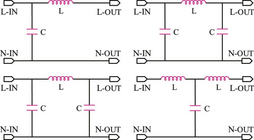
FIGURE 11. Impedance mismatch of passive EMI filters.
The CM and DM passive EMI filters are now mainly applicable to the motor drive control system. When the CM component of a signal attempts to go through the choke, it will meet a high impedance due to the inductance created by the magnetization of the core and the coils. In contrast to the CM behavior, the DM component of the signal encounters almost no impedance in the choke, and this phenomenon could be explained with the magnetic field compensation inside the core. If the core is not magnetized, then no inductance will appear in the line. The two- and three-phase common mode busbar cable chokes of the Würth Elektronik Group are widely used in conduction EMI filtering circuits because of their high impedance parameters, high power density, and diverse magnetic cores, as shown in Figure 12.
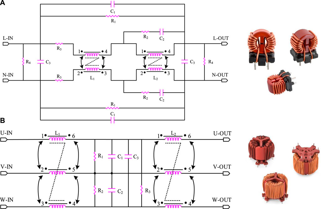
FIGURE 12. CM busbar cable choke and full-size diagram of (A) two-phase and (B) three-phase chokes.
3.1.3 Advanced PWM strategies
The angular frequency of the EMI spectrum is determined by the duty cycle and switching frequency of the PWM waveform. Based on the different frequencies, it can be divided into constant switching frequency PWM (CSFPWM) and variable switching frequency (VSFPWM): random switching frequency PWM (RSFPWM), period switching frequency PWM (PSFPWM), and model prediction switching frequency PWM (MPSFPWM). By using VSFPWM, the output voltage and current concentrated harmonics of the inverter in the low-frequency range are expanded to a wider band, which has a lower EMI peak value. As shown in Figure 13, the ordinate axis is of harmonic amplitude and

FIGURE 13. Harmonic magnitude of VSFPWM and CSFPWM: (A) RSFPWM, (B) PSFPWM, and (C) MPSFPWM.
3.1.4 Complex inverter circuit topologies
Section 3 elaborates how the EMI always exists in the motor drive control system based on the three-phase two-level inverter. To further minimize EMI, some improved inverter circuit topologies have been proposed, such as a three-level inverter and double-parallel inverter, as shown in Figure 14. Multistage inverters have smaller dv/dt, which can reduce the inverter output voltage and current harmonics. Unfortunately, more complex inverter circuit topologies have higher hardware costs and control complexity and reduce the power density of the system.
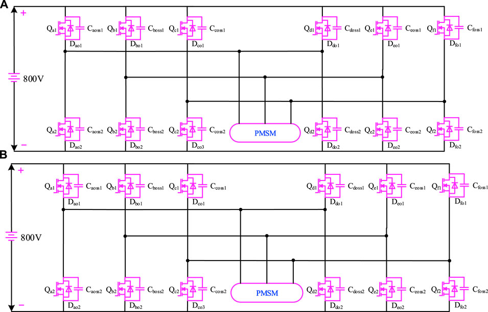
FIGURE 14. Complex inverter circuit topologies: (A) three-level inverter and (B) double-parallel inverter.
3.2 EMI solves problems of the motor drive control system
In order to suppress the conducted EMI noise of the motor drive control system, the passive filters with high insertion loss, wide frequency band, and strong currents are usually installed on the power battery pack, busbar cables, three-phase inverters, and motors, as shown in Figure 15.
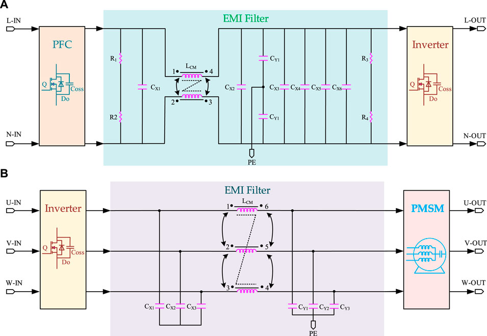
FIGURE 15. CM and DM passive EMI filters (A) between the power battery back to the inverter and (B) between the inverter to the PMSM.
The main cause of common-mode (CM) current in the motor drive control system is the parasitic parameters that couple to ground and shield the busbar cables and PMSM. The high-frequency current produces DM noise. After accurately capturing CM and DM effects, the EMC filters can be calculated to meet EMC standards.
4 Simulation validation and experiment results
In this section, a system-level equivalent circuit model of the motor drive control system based on the PMSM with the SiC MOSFET for NEEVs is established using SIMetrix/SIMPLIS circuit simulation software, which is used to simulate the conducted EMI noise effectively. The simulation model of the EMI setup is created by combining the component models reviewed in Section 2, Section 3, and Section 4 into a complete system model, demonstrating the model’s accuracy in predicting the measured conducted EMI noise. According to EMC Standards, the noise of the conducted EMC is measured in the laboratory, and the comparison between simulation and experimental results was analyzed.
4.1 Test arrangement
The experimental equipment is composed of two LISNs, an EMI receiver, a power battery pack, long four-core shielding busbar cables, a three-phase inverter, a PMSM, and a dynamometer machine. Under normal circumstances, the EMI receiver can measure the conductive interference voltage of the positive and negative power lines within a frequency range of 150 kHz–30 MHz by LISN.
The six SiC MOSFET drive voltage signals with a switching frequency of 10 KHz under the space vector PWM (SVPWM) control algorithm and three-phase winding current are given in Figure 16. The switching speed of the SiC MOSFET can be flexibly regulated with the changing of external RG (on) and RG (off) gate resistors.
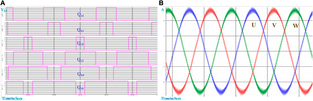
FIGURE 16. SVPWM control PMSM: (A) drive voltage signal and (B) three-phase winding current.
4.2 Analysis and comparison of simulation and experiment results
4.2.1 Complex inverter circuit topologies
Figure 17 shows the CM and DM voltage noise spectra curve for different switching frequencies. It can be observed that the CM voltage noise source makes up the majority in the low-frequency range, while the CM and DM are nearly equal in the high-frequency range. The reason is that the noise source in the low-frequency range is determined by the PWM modulation method, while the high-frequency range is caused by the turn-on and -off behavior and parasitic parameters of the SiC MOSFET. Obviously, the lower switching frequencies can effectively suppress the conducted EMC noise in the motor drive control system. However, due to the increase in size and volume of passive components, the lower switching frequencies cannot ensure higher power density. In order to balance the power density between the conducted EMC noise and motor drive control system, it is necessary to optimize the switching frequency.
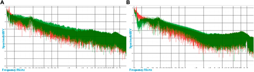
FIGURE 17. CM and DM voltage noise spectrum curves for switching frequencies (A) 10 KHz and (B) 20 KHz.
4.2.2 Load power
Figure 18 compares the spectrum curves of CM and DM noise under different load–power conditions. It can be found that the CM noise varies little with the load power in the low-frequency range, in contrast to the DM noise. The level of CM noise and DM noise under heavy load power is significantly higher than that under light load power.
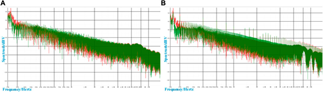
FIGURE 18. CM and DM voltage noise spectrum curves under (A) light and (B) heavy load power.
4.2.3 EMI filter
Figure 19 shows the total EMI noise spectrum curves obtained by simulation and experiment. Adding CM and DM passive EMI filters can reduce the conducted EMI noise of the motor drive control system and further affect the radiated interference.

FIGURE 19. Total EMI noise spectrum curves (A) before no EMI filter (B) after have filter.
5 Conclusion and future work
The urgent need to address energy and environmental challenges in the 21st century has become increasingly apparent alongside societal and industrial progress. With the rapid growth of the automotive industry, the motor drive control system of NEEVs has garnered the attention of the research community globally. SiC MOSFET and PMSM technologies have demonstrated substantial advancements in efficiency, performance, and power density, enabling the realization of high-speed motor controllers. However, this progress has also brought about intensified EMI noise. Therefore, it is imperative to carry out the mechanistic modeling, simulation, and experimental verification to study conducted EMI of the motor drive control system. This paper focuses on the system-level equivalent circuit model, encompassing the power battery pack, busbar cable, LISN, three-phase inverter, PMSM, and other power electronic components. This modeling approach not only establishes EMI sources and CM and DM propagation paths but also enables the simulation of control strategies and operating conditions. The simulation and experimental results corroborate the feasibility of the proposed scheme.
This paper contributes significantly by predicting the conducted EMI noise during the initial design phase, thereby avoiding additional PCB updating. It remains to be seen whether this work has multiple extensions. For instance, it is essential to assess the advantages of an active EMC filter in reducing the reliance on expensive CM and DM passive EMI filters. Additionally, while EMI simulation proves invaluable in analyzing conducted EMI and designing the necessary filters, further endeavors should concentrate on developing similar simulation tools for radiated EMI.
Data availability statement
The original contributions presented in the study are included in the article/supplementary material; further inquiries can be directed to the corresponding author.
Author contributions
CZ: conceptualization, data curation, formal analysis, investigation, methodology, project administration, resources, software, validation, visualization, writing–original draft, and writing–review and editing. JJ: supervision and writing–review and editing. MM: supervision and writing–review and editing. NA: supervision and writing–review and editing. XH: funding acquisition and writing–review and editing.
Funding
The author(s) declare financial support was received for the research, authorship, and/or publication of this article. This work was supported by the National Natural Science Foundation of China (No. U21A20170) and Ministry of Science and Technology of China (2019YFA0705703).
Acknowledgments
The authors acknowledge Infineon Technologies AG, Neubiberg 85579, Germany, and ABB Asea Brown Boveri Ltd., Zurich CH-8050, Switzerland. The authors thank their respective departments for providing the facilities for conducting the work.
Conflict of interest
Author CZ was employed by Infineon Technologies China Co., Ltd. and ABB Beijing Drive Systems Co.
The remaining authors declare that the research was conducted in the absence of any commercial or financial relationships that could be construed as a potential conflict of interest.
Publisher’s note
All claims expressed in this article are solely those of the authors and do not necessarily represent those of their affiliated organizations, or those of the publisher, the editors, and the reviewers. Any product that may be evaluated in this article, or claim that may be made by its manufacturer, is not guaranteed or endorsed by the publisher.
References
Alcázar-García, D., and José Luis Romeral, M. (2022). Model-based design validation and optimization of drive systems in electric, hybrid, plug-in hybrid and fuel cell vehicles. Energy 251 (A), 123719. doi:10.1016/j.energy.2022.123719
Barroso, D. G., Yang, Y., Machado, F. A., and Emadi, A. (2022). Electrified automotive propulsion systems: state-of-the-art review. IEEE Trans. Transp. Electrification 8 (2), 2898–2914. doi:10.1109/TTE.2021.3131917
Buenger, U., and Michalski, J. (2018). The impact of E-mobility in a future energy system dominated by renewable electricity. Chem. Ing. Tech. 90, 113–126. doi:10.1002/cite.201700084
Cheok, Q., Husaini, N. H., and Nauman, M. M. (2022). Economic feasibility of electric vehicles: a case study. Energy Storage 4 (3), e302. doi:10.1002/est2.302
Didat, M., New, C. D., Choi, S., and Lemmon, A. (2020). Improved methodology for conducted EMI assessment of wide band-gap power electronics. IEEE Open J. Power Electron. 3, 731–740. doi:10.1109/OJPEL.2022.3214761
Ding, X., Lu, P., and Shan, Z. (2021). A high-accuracy switching loss model of SiC MOSFETs in a motor drive for electric vehicles. Appl. Energy 291, 116827. doi:10.1016/j.apenergy.2021.116827
Gong, X., and Ferreira, J. A. (2010). “Extracting the parameters of a common mode EMI equivalent circuit model for a drive inverter,” in The 2010 International Power Electronics Conference - ECCE ASIA, Sapporo, Japan, 892–899. doi:10.1109/IPEC.2010.5543356
Gurpinar, E., Wiles, R., Ozpineci, B., Raminosoa, T., Zhou, F., Liu, Y., et al. (2018). “SiC MOSFET-based power module design and analysis for EV traction systems,” in 2018 IEEE Energy Conversion Congress and Exposition (ECCE), Portland, OR, USA, 1722–1727. doi:10.1109/ECCE.2018.8557609
He, R., Xu, Y., Walunj, S., Yong, S., Khilkevich, V., Pommerenke, D., et al. (2020). Andreas. Modeling strategy for EMI filters. IEEE Trans. Electromagn. Compat. 62 (4), 298–309. doi:10.1109/TEMC.2020.3006127
Hossain, M. S., Kumar, L., El Haj Assad, M., and Alayi, R. (2022a). Advancements and future prospects of electric vehicle technologies: a comprehensive review. Complexity 2022, 1–21. doi:10.1155/2022/3304796
Hossain, M. S., Kumar, L., Islam, M. M., and Selvaraj, J. (2022b). A comprehensive review on the integration of electric vehicles for sustainable development. J. Adv. Transp. 2022, 1–26. doi:10.1155/2022/3868388
Hu, J., Xu, X., Cao, D., and Liu, G. (2018). Analysis and optimization of electromagnetic compatibility for electric vehicles. IEEE Electromagn. Compat. Mag. 8 (4), 50–55. doi:10.1109/MEMC.2019.8985599
Hu, X., Han, J., Tang, X., and Lin, X. (2021). Powertrain design and control in electrified vehicles: a critical review. IEEE Trans. Transp. Electrification 7 (3), 1990–2009. doi:10.1109/TTE.2021.3056432
Jia, X., Hu, C., Dong, B., He, F., and Wang, H. (2020). “Dehong. System-level conducted EMI model for SiC powertrain of electric vehicles,” in 2020 IEEE Applied Power Electronics Conference and Exposition (APEC), New Orleans, LA, USA, 885–892. doi:10.1109/APEC39645.2020.9124375
Jia, X., Hu, C., Dong, B., He, F., Wang, H., and Xu, (2021). Influence of system layout on CM EMI noise of SiC electric vehicle powertrains. CPSS Trans. Power Electron. Appl. 6 (4), 298–309. doi:10.24295/CPSSTPEA.2021.00028
Kalair, A., Abas, N., Saleem, M. S., Kalair, A. R., and Khan, N. (2021). Role of energy storage systems in energy transition from fossil fuels to renewables. Energy Storage 3, e135. doi:10.1002/est2.135
Kene, R., Olwal, T., van Wyk, , and Barend, J. (2021). Sustainable electric vehicle transportation. Sustainability 13 (22), 12379. doi:10.3390/su132212379
Kumar, M., and Jayaraman, K. (2022). Design of a modified single-stage and multistage EMI filter to attenuate common-mode and differential-mode noises in SiC inverter. EEE J. Emerg. Sel. Top. Power Electron. 10 (4), 4290–4302. doi:10.1109/JESTPE.2021.3133374
Li, Z., Wu, L., Xu, Y., and Zheng, X. (2022). Stochastic-weighted robust optimization based bilayer operation of a multi-energy building microgrid considering practical thermal loads and battery degradation. IEEE Trans. Sustain. Energy 13 (2), 668–682. doi:10.1109/TSTE.2021.3126776
Liu, C., Chau, K. T., Lee, C. H. T., and Song, Z. (2021). A critical review of advanced electric machines and control strategies for electric vehicles. Proc. IEEE 109 (6), 1004–1028. doi:10.1109/JPROC.2020.3041417
Liu, Y., See, K. Y., Yin, S., Simanjorang, R., Gupta, A. K., and Lai, J.-S. (2019). Equivalent circuit model of high power density SiC converter for common-mode conducted emission prediction and analysis. IEEE Electromagn. Compat. Mag. 8 (1), 67–74. doi:10.1109/MEMC.2019.8681373
López, I., Matallana, A., Andreu, J., and Kortabarria, I. (2019). Next generation electric drives for HEV/EV propulsion systems: technology, trends and challenges. Renew. Sustain. Energy Rev. 114, 109336. doi:10.1016/j.rser.2019.109336
Ma, G., Ghasemi, M., and Song, X. (2018). Integrated powertrain energy management and vehicle coordination for multiple connected hybrid electric vehicles. IEEE Trans. Veh. Technol. 67 (4), 2893–2899. doi:10.1109/tvt.2017.2780268
Mihet-Popa, L., and Saponara, S. (2018). Toward green vehicles digitalization for the next generation of connected and electrified transport systems. Energies 11 (11), 3124. doi:10.3390/en11113124
Oswald, N., Anthony, P., McNeill, N., and Stark, B. H. (2014). An experimental investigation of the tradeoff between switching losses and EMI generation with hard-switched all-Si, Si-SiC, and all-SiC device combinations. IEEE Trans. Power Electron. 29 (5), 2393–2407. doi:10.1109/TPEL.2013.2278919
Ozaki, T., Funaki, T., and Ibuchi, T. (2017). “An experimental study on conducted noise emission for PMSM drive with SiC inverter Conducted noise reduction by snubber circuit,” in 2017 IV International Electromagnetic Compatibility Conference, Ankara, Turkey (EMC Turkiye), 1–6. doi:10.1109/EMCT.2017.8090353
Ranjan Kumar, R., and Kumar, A. (2020). Adoption of electric vehicle: a literature review and prospects for sustainability. J. Clean. Prod. 253, 119911. doi:10.1016/j.jclepro.2019.119911
Rao, H., Zhou, B., Zhang, F., Xu, Y., Hong, C., and Yang, J. (2021). “Electromagnetic compatibility of power electronic devices in electric vehicle drive system,” in 2021 IEEE 4th International Conference on Electronics Technology (ICET), Chengdu, China, 509–512. doi:10.1109/ICET51757.2021.9451118
Rifan, M., Media's, E., and Firmansyah, H. (2021). Intelligent control system for high efficiency Electric Vehicles. IOP Conf. Ser. Mater. Sci. Eng. 1098 (4), 042072. doi:10.1088/1757-899X/1098/4/042072
Robles, E., Matallana, A., Aretxabaleta, I., Andreu, J., Fernandez, M. l., Martin, L., et al. (2022). The role of power device technology in the electric vehicle powertrain. Int. J. Energy Res. 46 (15), 22222–22265. doi:10.1002/er.8581
Safayet, A., and Islam, M. (2021). Modeling of conducted emission for a three-phase motor control inverter. IEEE Trans. Industry Appl. 37 (2), 1202–1211. doi:10.1109/TIA.2021.3052744
Tran, D.-D., Vafaeipour, M., El Baghdadi, M., Barrero, R., Van Mierlo, J., and Hegazy, O. (2020). Thorough state-of-the-art analysis of electric and hybrid vehicle powertrains: topologies and integrated energy management strategies. Renew. Sustain. Energy Rev. 119, 109596. doi:10.1016/j.rser.2019.109596
Van Do, T., Joao Pedro, F., Li, K., and Boulon, L. (2021). Wide-bandgap power semiconductors for electric vehicle systems: challenges and trends. IEEE Veh. Technol. Mag. 16 (4), 89–98. doi:10.1109/MVT.2021.3112943
Wang, K., Lu, H., Chen, C., and Xiong, Y. (2022). Modeling of system-level conducted EMI of the high-voltage electric drive system in electric vehicles. IEEE Trans. Electromagn. Compat. 64 (3), 741–749. doi:10.1109/TEMC.2022.3147521
Wang, Y. S., Guo, H., Yuan, T., Ma, L. F., and Wang, C. (2021). Electromagnetic noise analysis and optimization for permanent magnet synchronous motor used on electric vehicles. Eng. Comput. 38 (2), 699–719. doi:10.1108/EC-02-2020-0070
Wu, Z., Jiang, H., Zheng, Z., Qi, X., Mao, H., Liu, L., et al. (2022). Dynamic dv/dt control strategy of SiC MOSFET for switching loss reduction in the operational power range. IEEE Trans. Power Electron. 37 (6), 6237–6241. doi:10.1109/TPEL.2021.3137825
Yang, Y., He, Q., Fu, C., Liao, S., and Tan, P. (2020). Efficiency improvement of permanent magnet synchronous motor for electric vehicles. Energy 213, 118859. doi:10.1016/j.energy.2020.118859
Zhai, L., Hu, G., Song, C., Lv, M., and Zhang, X. (2021). Comparison of two filter design methods for conducted EMI suppression of PMSM drive system for electric vehicle. IEEE Trans. Veh. Technol. 70 (7), 6472–6484. doi:10.1109/TVT.2021.3080924
Zhang, B., and Wang, S. (2021). “Radiated electromagnetic interference modeling for three phase motor drive systems with SiC power modules,” in 2021 IEEE Applied Power Electronics Conference and Exposition (APEC), Phoenix, AZ, USA, 2243–2250. doi:10.1109/APEC42165.2021.9487419
Zhao, X., Wang, L., Zhou, Y., Pan, B., Wang, R., Wang, L., et al. (2022). Energy management strategies for fuel cell hybrid electric vehicles: classification, comparison, and outlook. Energy Convers. Manag. 270, 116179. doi:10.1016/j.enconman.2022.116179
Keywords: EMI, new energy electric vehicles, SiC MOSFET, PMSM, motor drive control system, conducted emissions, suppression measures
Citation: Zhang C, Jasni J, Mohd Radzi MA, Azis N and He X (2024) Research and analysis of electromagnetic interference of a motor drive control system based on PMSM with SiC MOSFET for new energy electric vehicles. Front. Energy Res. 11:1338212. doi: 10.3389/fenrg.2023.1338212
Received: 14 November 2023; Accepted: 12 December 2023;
Published: 08 March 2024.
Edited by:
Zhengmao Li, Aalto University, FinlandReviewed by:
Shuangchun Xie, Nanyang Technological University, SingaporeJingwei Zhu, Nanyang Technological University, Singapore
Copyright © 2024 Zhang, Jasni, Mohd Radzi, Azis and He. This is an open-access article distributed under the terms of the Creative Commons Attribution License (CC BY). The use, distribution or reproduction in other forums is permitted, provided the original author(s) and the copyright owner(s) are credited and that the original publication in this journal is cited, in accordance with accepted academic practice. No use, distribution or reproduction is permitted which does not comply with these terms.
*Correspondence: Chi Zhang, ee.zhangchi@gmail.com