A decision-making method for the operation flexibility enhancement of hybrid cascaded MTDC
 Yuhan Wang
 Zhou Li*
  Yuanshi Zhang
- School of Electrical Engineering, Southeast University, Nanjing, China
To enable the integration of large-scale renewable energy, hybrid HVDC technology, which combines the technical advantages of LCC-HVDC and VSC-HVDC, is being gradually deployed in the power grid nowadays. The operation of the Wu-dong-de Hybrid DC Project and the Jian-su Hybrid cascaded MTDC Project has proved its advantages. However, for the simultaneous application of different converter station technologies in the system, the control strategies become complex. Issuing appropriate control instructions to ensure system stability according to operational requirements is an issue that cannot be ignored in decision-making. Even under abnormal conditions, when the topology changes due to various failure scenarios, reasonable decision-making and precise control instruction definitions are required. To achieve flexible planning of the MTDC system, this paper presents a decision-making method for control strategies of a hybrid cascaded MTDC system, which analyzes the control strategy combinations selected for normal and abnormal conditions of the MTDC system. In addition, a control instruction calculating method and decision-making process for precise control in normal and abnormal control conditions is proposed. Simulation results based on a five-terminal hybrid cascaded MTDC in PSCAD/EMTDC have verified the effectiveness of the proposed method.
1 Introduction
High-voltage direct current technology, including LCC-HVDC and VSC-HVDC, plays an important role in power transmission and allocation, as well as variable renewable energy (VRE) regulation (Liu et al., 2015; Alves et al., 2020). LCC-HVDC power transmission technology has the advantages of large transmission capacity, a high voltage level, low manufacturing cost, and high reliability (Kwon et al., 2018; Chen et al., 2022), making it widely used in large-capacity and long-distance power transmission systems. VSC-HVDC power transmission technology (Flourentzou et al., 2009; Wang R. et al., 2020; Zhao and Tao, 2021; Xu et al., 2023) has advantages of flexible control and easy power flow reversal, making it more advantageous in the fields of large-scale renewable energy integration (Wang et al., 2022), passive grid power supply, and multi-terminal HVDC transmission (Rao et al., 2019; Li et al., 2021a; Li et al., 2021b; Li et al., 2022).
Hybrid HVDC transmission technology (Rao et al., 2022) combines the technical advantages of LCC-HVDC and VSC-HVDC, which not only overcomes the challenges of long-distance transmission with high-power but also solves VRE integration, power quality, and grid asynchronous interconnection in a power system, and is gradually applied in engineering. Currently, the Wu-dong-de Hybrid DC Project and the Jian-su Hybrid cascaded MTDC Project in China are in operation and have proven their worth (Haleem et al., 2019; Reza Ahrabi et al., 2022).
However, due to the simultaneous use of VSC and LCC commutation technologies (Aziz et al., 2019; Wang T. et al., 2020), the physical mechanism of MTDC is more complex. In this system, there are control requirements related to multiple voltage levels, as well as the determination of power commands at different converter stations. Under normal operating conditions, a variety of available control modes can be selected for different converters, and the control strategy combinations without restriction are complex and confusing for decision-making. In addition, issuing appropriate control instructions to ensure system stability according to operational demands is a problem that cannot be ignored in decision-making. Under abnormal operating conditions, permanent faults occur on the AC or DC side of the system, leading to changes in the topology (Ren et al., 2023). To reduce the impact of faults, decision-making methods are also needed to provide the corresponding combinations of control strategies and solve the allocation problem of transmission power of faulty poles.
Previous research has mainly focused on studying a single strategy in specific scenarios, while little research has been performed at the system level to select control strategy combinations for hybrid cascaded MTDC systems with different converter stations, which cannot provide appropriate control strategies and precise instructions for a system based on regulatory requirements (Li et al., 2020). To achieve flexible planning of the MTDC system, it is necessary to analyze the coupling relationship between different converter stations in the hybrid cascaded MTDC system, sort out various control strategies adopted by multiple converter stations, and identify feasible control strategy combinations under normal and abnormal conditions.
In view of the aforementioned considerations, this paper proposes a control strategy decision-making method for the hybrid cascaded MTDC system with the following contributions:
1) For normal control, a two-stage analysis method is proposed for the selection of control strategy combinations for the selection of the hybrid cascaded MTDC system. In the first stage, VSCs are considered VSCBs, and the control strategies of series LCCs are determined. In the second stage, the station-level control strategies for VSCs are determined.
2) For abnormal control, abnormal conditions that cause the quitting operation of converter stations are classified. In addition, control strategy combinations of the selection method including three control strategy combinations that can deal with the quitting operation of converter stations are proposed.
3) A control instruction calculating method and decision-making process for normal and abnormal controls are proposed. According to the calculation method, under normal conditions, the control instructions are accurately calculated and assigned to the controllers of the MTDC system. Under abnormal conditions, reasonable instructions for converters in bipolar MTDC are calculated to achieve the transfer of active power in faulty poles.
The rest of the paper is organized as follows: in Section 2, the topology and control strategies of the hybrid cascaded MTDC system are analyzed, and the decision-making method for control strategies and the control instruction calculating method for the hybrid cascaded MTDC system under normal and abnormal conditions are proposed. In Section 3, simulations in different scenarios of different control strategies are analyzed to verify the effectiveness of the proposed strategy. Finally, the conclusions are drawn in Section 4.
2 Decision-making method for the control strategy of a hybrid cascaded MTDC system
2.1 Features and control demand of a hybrid cascaded MTDC
As shown in Figure 1, the topology of the hybrid cascaded MTDC system is based on the real hybrid HVDC project. The project is responsible for transmitting abundant hydropower power from the Baihetan Hydropower Station, which is the second largest hydropower station in the world, to the southern part of Jiangsu Province. The DC system adopts a bipolar topology, with the rectifier side composed of LCCs (±800 kV) and the inverters composed of parallel-connected VSCs (±400 kV) connected in series with LCCs (±400 kV). Three VSCs connected in parallel can be equated to a VSCB (Bank of VSCs) as they are at the same voltage level, as shown in Figure 2, and their capacitance is equal to their sum. LCC and VSC inverters are connected to different AC buses and with weak interactions.

FIGURE 1. Hybrid cascaded MTDC system.
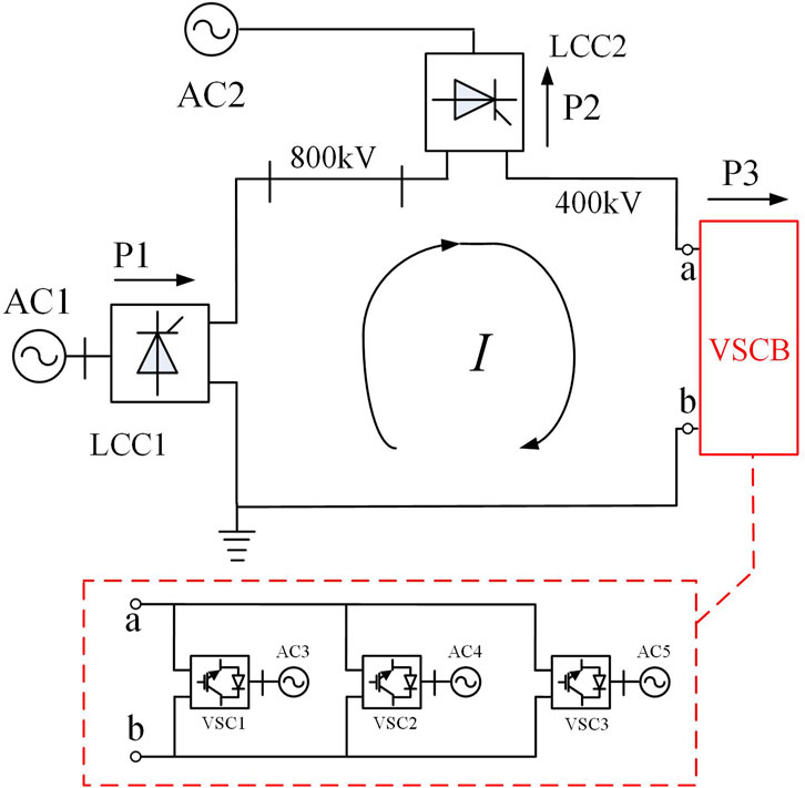
FIGURE 2. Unipolar equivalent circuit of a hybrid cascaded MTDC system.
To facilitate the analysis of control strategies for hybrid cascaded MTDC systems, LCCs and VSCBs can be categorized into two types, namely, the power control station and voltage control station, depending on the overall control effect of LCC/VSCB, which will be discussed in Section 2.2.
Based on the analysis of the topology of the hybrid cascaded MTDC system, features and control demands of the system can be summarized into the following rules (Li et al., 2020):
Rule 1: Since the receivers LCC and VSCB are connected in series, and there are two voltage levels in the transmission line, to achieve stable control in a hybrid cascade system, it is necessary to have two converter stations serving as voltage control stations. Since the system converter station operates in the series mode, the system must have a converter station that serves as a power control station.
Rule 2: The status of the hybrid cascaded MTDC system can be calculated using Eq. 1 as follows:
where
Rule 3: The topologies of the hybrid cascaded MTDC system are symmetrical. Therefore, the control strategies in each pole can be symmetrical accordingly.
2.2 Decision-making method for normal control
2.2.1 Control strategy combination selecting method for normal control
To improve the flexibility of the system, different control strategies can be used to maintain the operation of converter stations under different objectives. However, since the hybrid cascaded MTDC system includes both LCCs and VSCs, many available control strategy combinations can be selected for different converters, of which the combination of control strategies without a constraint is complex and confusing for decision-making. Thus, to solve the decision-making problem, reasonable combinations of control strategies based on the system topology and demands are analyzed in this section.
The analysis process is divided into two stages. In the first stage, shown in Figure 3, VSCs are considered VSCBs, and the control strategies of series LCCs are determined. In the second stage, shown in Figure 4, station-level control strategies for VSCs are determined, which solves the problem of difficulties in decision-making.
1) Stage 1: The control strategies of LCCs are analyzed under the assumption that VSCs are considered VSCBs. The functions of each converter station (power control station/voltage control station) are determined. Since the selection of control strategies is strongly related to power regulation instructions under normal circumstances, recommended operation control strategies can be provided based on power dispatch instructions from different ends, combined with Figure 3.
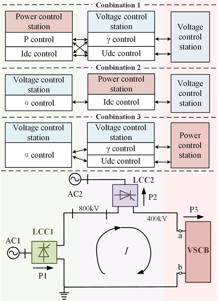
FIGURE 3. Selection of control strategy combinations in the first stage.
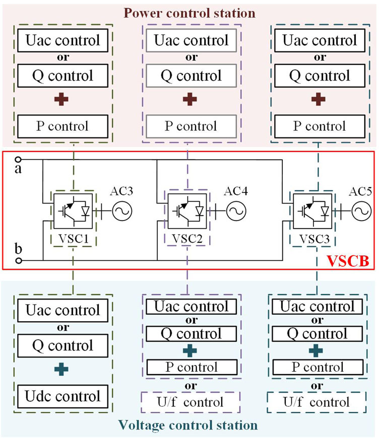
FIGURE 4. Selection of control strategy combinations in the second stage.
When there is a scheduling requirement for LCC1, to be selected as the power control station, LCC2 and VSCB are simultaneously selected as the voltage control station. Based on combination 1 in Figure 3, there are two recommended control modes for LCC1: the constant power control mode or constant DC current control mode. In the constant power control mode, LCC1 directly controls the active power transmission on the AC side. In the constant DC current control mode, power control can be achieved through calculations based on the voltage control station.
When there is a system power dispatch command at LCC2, LCC2 can be used as a power control station or voltage control station for its current coupling relationship with other converter stations. Based on combination 1, when LCC2 is selected as a power control station, it operates in a constant DC current control mode. Based on combinations 1 and 3, when LCC2 is used as a voltage control station, LCC1 or VSCB can also be selected as a power control station to control line current and perform calculations, using current coupling relationships to achieve indirect power control.
When receiving system power scheduling commands in VSCs, VSCB can serve as a voltage control station or power control station.
2) Stage 2: The control strategies at the station level are determined for three VSCs. If the VSCB serves as a voltage control station and not all VSCs have power control commands, VSCs without power control commands can be selected to operate in a constant DC voltage control mode, while other VSCs have no restrictions (see Figure 4). If the power control requirement exists in all VSCs, VSCB is selected as the power control station, which means that all VSCs adopt the constant power control mode. In addition, each VSC station can select appropriate reactive power control strategies based on the demand on the AC side of the converter station nearby.
2.2.2 Control instruction calculating method and decision-making process for normal control
After the aforementioned analysis and considering the upper and lower limit issues, equality constraints, and compatibility issues between different converter station control strategies during the operation and control process of hybrid cascaded MTDC systems, the control strategy to achieve the target steady-state operating point of the system can be derived from the following process:
Step 1: Obtain scheduling requirements and select corresponding control strategies. For example, if active power control is required at a converter station in a hybrid cascaded MTDC system, control strategies that can be applied in each converter station can be seen in Figure 3 and Figure 4.
Step 2: Calculation of the operating point. Based on the conditions mentioned in step 1 and the two voltage levels of the system, the system mathematical model within a five-terminal hybrid cascade MTDC system can be expressed as in Eq. 1. Without considering the active power feedback of VSC, the transmission power of VSC in VSCB which adopts a constant power control mode can be expressed as Eq. 2:
where P3 is calculated in Eq. 1.
Step 3: Control reference instruction assignment (U1, U2, U3, P1, P2, P3, α, γ, and Idc). The control reference needed is assigned to the controllers according to control strategy combinations selected in step 1.
2.3 Decision-making method for abnormal control
2.3.1 Classification of abnormal conditions in a hybrid cascaded MTDC system
As shown in Figure 5, abnormal conditions in a hybrid cascaded MTDC system can be divided according to the duration of the fault. If faults in the MTDC system can be quickly cleared, such faults are classified as transient abnormal conditions, after which the decision-making method for normal control can be re-run for the MTDC system (see Section 2.2). Otherwise, such faults belong to permanent abnormal conditions, and these types of faults will inevitably cause the converter in the system to quit operation.
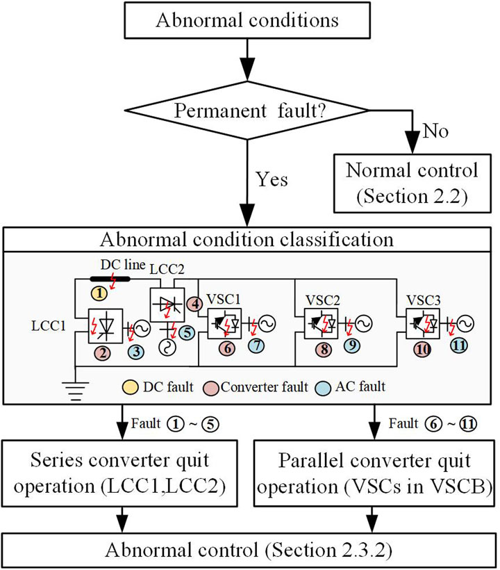
FIGURE 5. Classification of abnormal conditions.
Permanent abnormal conditions in a hybrid cascaded MTDC system include short circuits and broken line faults in DC and AC lines. When the system is in a permanent abnormal condition, it is necessary to classify the abnormal conditions. The persistence of the fault will cause the neighboring inverter to quit operation. According to the topology analysis in Figure 1, if there is an AC fault near the converter station, both poles of the converter station will quit operation simultaneously due to the connection to the same AC bus. If the fault is in the converter itself or in the DC line, it is generally a unipolar fault. In the following section, decision-making will be analyzed under abnormal conditions based on the quitting of the converter station and the original control strategy combinations of the system.
2.3.2 Control strategy combination selecting method for abnormal control
Due to the bipolar topology of the MTDC system, an independent analysis of the unipolar/bipolar fault is required when the system is in a permanent abnormal condition. It is worth noting that this article mainly analyzes common faults (including N-1) in the MTDC system.
In the case of unipolar faults, the topology of the system fault pole needs to be adjusted after the fault as the converter station quits. Moreover, there are completely different control strategies between the DC pole without fault and the faulty pole of the system. As shown in Figure 6, there are three strategy combinations for the fault pole which can deal with the topology adjustment after the fault. In addition, the DC pole without fault can adjust the power reference value to partially transfer the faulty pole power to itself.
1) According to mode 1 shown in Figure 6, the topology and control strategy of fault response are to solve the operational difficulty when LCC1 or LCC2 quits operation due to faults. In this fault response mode, VSCB must operate as a voltage control station to maintain the DC voltage. According to the principle of voltage control stations, taking VSC1 as an example in Figure 6, one VSC needs to be selected to operate in a constant DC voltage mode internally in VSCB, while the other two converter stations are not restricted in their operating modes.
2) According to mode 2, the parallel converter quits operation in abnormal conditions, when VSCB operates as a power control station. Mode 2 of fault response is to address the fault of VSC quit operation from VSCB, which operates as a power control station. In this mode, after the fault occurs, it is not necessary to adjust the control strategy of each converter station.
3) According to mode 3, VSCB operates as a voltage control station. Mode 3 of fault response is to address the fault of VSC quit operation from VSCB, which operates as a voltage control station. When a fault occurs, if the quit VSC is in constant power or the U/f control mode, the control strategy adopted by inverters remains unchanged. If the quit VSC operates in the constant DC voltage control mode, the system needs to select another VSC for changing the control strategy to the constant DC voltage control mode.
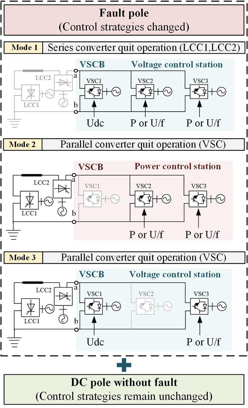
FIGURE 6. Feasible topology and control strategy combinations after a fault.
When analyzing bipolar faults in the system, due to the identical topology and control strategy before the positive and negative pole faults, the control strategy after the fault is identical as well and can replicate the control mode for unipolar faults.
After completing the post-fault analysis of the operational control strategy, the calculation of instructions for each converter station with differences between unipolar and bipolar faults will be discussed in detail in Section 2.3.3.
2.3.3 Control instruction calculating method and decision-making process for abnormal control
Based on the previous analysis, we can conclude that the three modes of control strategy combinations to cope with topology adjustment in Figure 6 mainly involve the analysis of VSC. Therefore, the control instructions for each converter station within VSCB must be calculated first, and then, the reference value of the MTDC system can be calculated according to Eq. 1. In this section, a control instruction calculation method and decision-making process based on the power transfer capability of bipolar MTDC (see Figure 7) are proposed to achieve power transfer between converter stations under fault conditions. The calculation method for the control instructions of the VSCB instruction used for abnormal control is as follows:
1) Calculation of control instructions of mode 1. If the fault is a bipolar fault, VSC that can provide active power support will provide power to the other VSCs, as shown in Eq. 3, and there is one VSC for each pole operating in a constant DC voltage control mode, instructions of which can be calculated by Eq. 4:
where
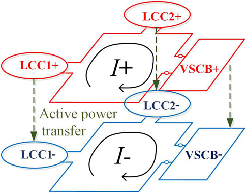
FIGURE 7. Active power transfer under abnormal conditions.
If the fault is a unipolar fault, there is no need for a DC pole without fault to modify the control reference.
2) Calculation of control instructions of mode 2. All the remaining VSCs in each pole operate in the constant power control mode, and the power reference values are shown in Eq. 5:
where
3) Calculation of control instructions of mode 3. If the VSC that has failed is in the constant power or U/f control mode, the active power reference values of remaining VSCs, which operate in the constant power control mode, are shown in Eq. 6:
where
If the VSC that has failed is in the constant DC voltage control mode, one VSC in each pole should be selected to operate in the constant DC voltage control mode, and the control instructions are calculated according to Eq. 7:
where U3 is calculated according to Eq. 1 after the fault. Thus, in abnormal conditions, the decision-making process consists of the following steps:
Step 1: Obtain the status of the quit converter and the status of the system during normal operation before the fault. According to the method in Section 2.3.2, determine the system structure and operation control strategy after the fault.
Step 2: Operation point calculation under abnormal conditions. The calculation of VSCB for adjusting control instructions under different control strategy combinations can be calculated by Eqs 3–7, and then, the system operational point can be calculated by Eq. 1.
Step 3: Control instruction assignment. Assign the calculated instruction values to the corresponding converter station controllers.
3 Simulations and analyses
3.1 Simulation system and scenarios
To verify the effectiveness of the control strategy selection method for the hybrid cascaded MTDC system, a five-terminal simulation system based on the bipolar hybrid HVDC project is set in PSCAD/EMTDC, as shown in Figure 1.
In this simulation system, LCC1 operates as a rectifier, LCC2 operates as an inverter to transmit power to the AC side, and under normal circumstances, VSCs operate as inverters. The rated value of power in the rectifier side is 4000 MW, the voltage is 800 kV, the rated value of power in the inverter side LCC2 is 2000 MW, the rated voltage is 400 kV, the rated value of power in the inverter side VSC is 1000 MW, the rated voltage is 400 kV, and the system rated current is 5 kA.
In this paper, active power allocation scenarios for the five-terminal DC system during winter and summer peak periods are set to verify the effectiveness of the normal control strategy. In addition, scenarios with bipolar and unipolar faults are set to verify the effectiveness of the decision-making method for abnormal control.
3.2 Scenario 1: Power allocation during the hydropower peak period in summer
Scenario 1 is set up to verify the effectiveness of the control strategy combination selection method in allocating power during the summer hydropower peak using the following steps:
Step 1: There is a need for power control for the sending-end LCC1 during the summer hydropower peak. Based on the strategies in Figure 3, the rectifier side can be selected to operate in the constant DC current control mode, the inverter side can be selected to operate in the constant arc extinction angle control mode, any VSC is selected as the voltage control station, and the other VSCs operate in the constant power control mode to distribute the transmission power of the sending LCC. This control mode can prevent large changes of current in the hybrid cascade system while maintaining the highest voltage on the inverter side under normal conditions, which is economical.
Step 2: After selecting a control strategy combination, the control variables can be calculated according to Eqs. 1, 2. The active power of the sending-end LCC gradually increases from 50% to 75% and finally to the rated power. According to the standard operating voltage calculation, the voltage on the rectification side of the system is 800 kV, and the voltage of the inverter is 400 kV. Based on the constraints of the aforementioned variables, the calculated control instructions are shown in Table 1.
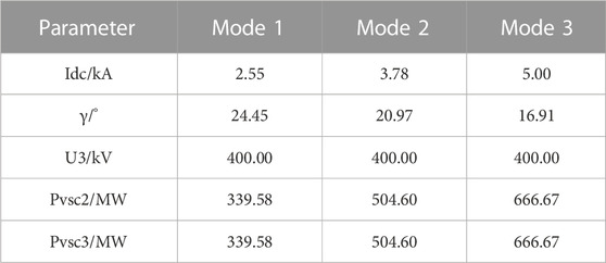
TABLE 1. Calculation results of the decision-making method in scenario 1.
Step 3: Based on the control strategy combination selected in step 1, the corresponding control variables can be assigned according to the calculation results in step 2 to obtain the actual operating point of the system, as shown in Figure 8.
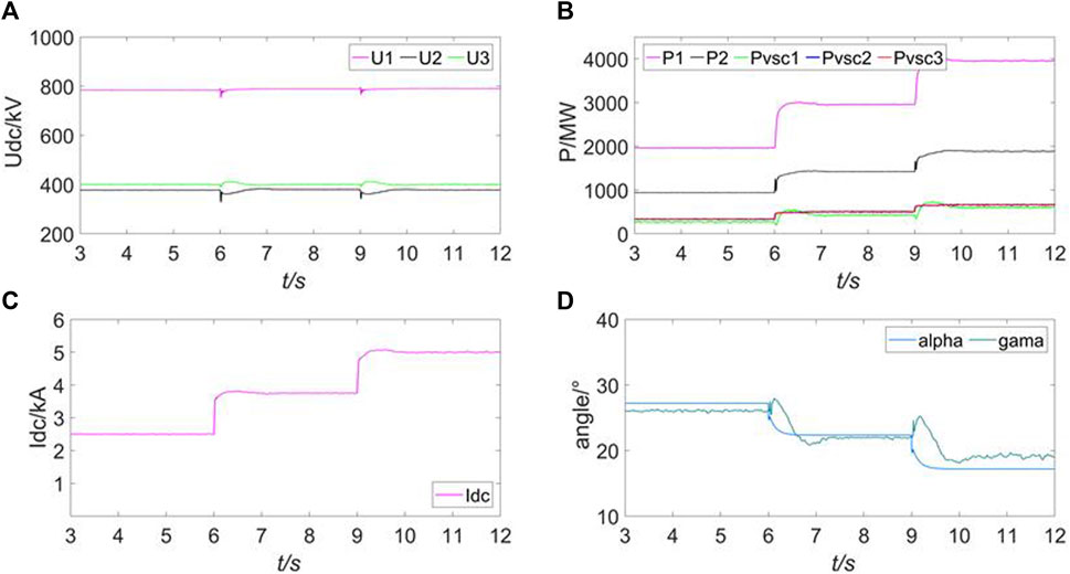
FIGURE 8. Simulation results of different operation modes in scenario 1. (A) DC voltage of each converter. (B) active power of each converter. (C) DC current of the DC grid. (D) Trigger delay angle of LCC1 and the extinction angle of LCC2.
The simulation results in Figure 8 show that the control instructions are accurately assigned to the system and that the hybrid cascaded MTDC system operates normally in summer.
3.3 Scenario 2: Power allocation during the wind power peak period in winter
Scenario 2 is set to verify the effectiveness of the control strategy selection method for VSC power reverse transmission during winter.
Step 1: During the wind power peak in winter, the Baihetan Hydropower Station connected to the LCC1 converter station is in the dry season with a transmission capacity of 2000 MW. At the same time, in winter, there is a surplus of wind power in the AC power grid connected to the receiving converter station VSC1, and the active power is sent back to the DC power grid. Based on the control strategy selection method, VSC2/VSC3 have power control demand and operate in the constant power control mode, and VSC1 operates in the constant DC voltage control mode to collectively absorb the transmission power from LCC1. Therefore, VSCB is generally equivalent to a voltage control station. Then, LCC1 operates in the constant α control mode as a voltage control station, while LCC2 can operate in the constant DC current control mode as a power control station.
Step 2: After selecting a control strategy combination, the controlled variables can be calculated according to Eqs. 1, 2. At this time, the transmission power of LCC1 is 2000 MW, and VSC1 is −500 MW. After calculating the standard operating voltage, the voltage of LCC1 is 800 kV, and the voltage of VSCB is 400 kV. Based on the constraints in the system, the calculated control instructions are shown in Table 2:
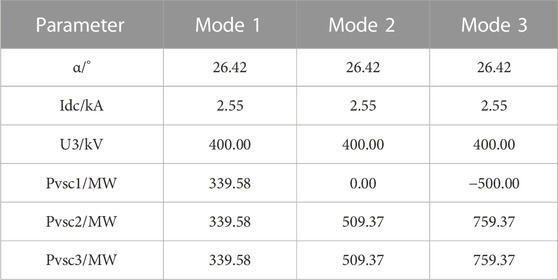
TABLE 2. Calculation results of the decision-making method in scenario 2.
Step 3: Based on the control strategy combination selected in step 1, control reference instructions are assigned to the corresponding converter station controllers based on the calculation results.
The simulation results in Figure 9 show that VSCB can achieve stable and accurate power support capability under the condition of VSC1 power feedback.
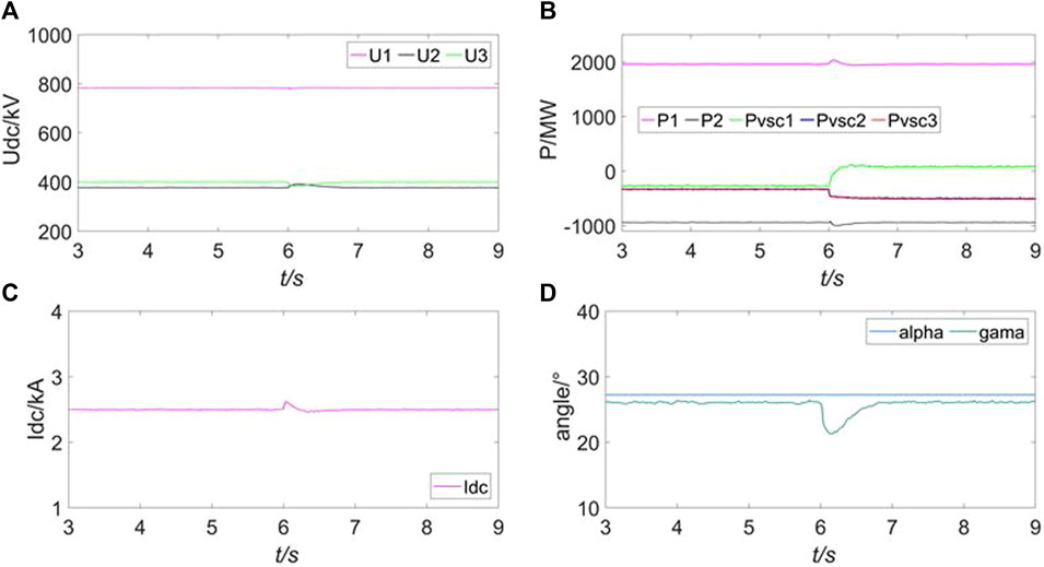
FIGURE 9. Simulation results of different operation modes in scenario 2. (A) DC voltage of each converter. (B) Active power of each converter. (C) DC current of the DC grid. (D) Trigger delay angle of LCC1 and the extinction angle of LCC2.
3.4 Scenario 3: Unipolar fault of VSC1 during the hydropower peak period in summer
Scenario 3 is set to verify the effectiveness of the decision-making method for abnormal control of high hydropower generation in summer and VSC1 quitting operation due to faults.
Step 1: Similar to scenario 1, LCC1 is in a state of full power transmission during the period of high hydropower generation in summer. Under normal circumstances, the transmission capacity of LCC1 is 4000 MW and that of LCC2 and VSCB are 2000 MW. At this time, both VSCB and LCC2 serve as voltage control stations. At t = 6s, a fault occurred in the positive pole of VSC1, and it was unable to automatically return to normal control after the transient process. According to mode 3 in Section 2.3.2, if the VSC that has quit adopts the constant DC voltage control mode, another VSC in the VSCB needs to be selected to control the DC voltage (VSC2 is selected in this example), while the control modes of the other converter stations remain unchanged.
Step 2: After selecting a control strategy combination, according to Eq. 6, the control variables for the VSCB are calculated. VSCs adopting constant power control increase the reference value based on control instructions and absorb excess active power. In addition, according to Eq. 1, the voltage reference values of the positive and negative VSCBs are adjusted simultaneously so that the transmission power of LCC2 remains unchanged; the calculated control instructions are shown in Table 3:

TABLE 3. Calculation results of the decision-making method in scenario 3.
Step 3: Based on the control strategy combination selected in step 1, assign the corresponding control variables according to the calculation results in step 2 to obtain the actual operating point of the system. As shown in Figure 10, under the permanent fault, according to the scheduling strategy under the fault, the system adjusts the voltage and power reference values to transfer the faulty pole power part to the VSCs in the normal pole, achieving steady operation of the system.
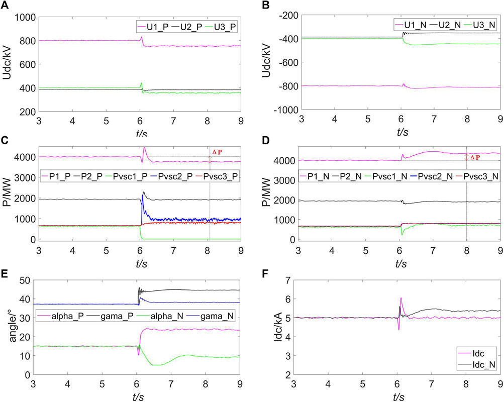
FIGURE 10. Simulation results of different operation modes in scenario 3. (A) DC voltage of a positive pole. (B) DC voltage of a negative pole. (C) Active power of a positive pole. (D) Active power of a negative pole. (E) Trigger delay angle of LCC1 and the extinction angle of LCC2. (F) DC current of the DC grid.
The simulation results in Figure 10 indicate that when VSC1 quits operation due to a fault, the calculation method for abnormal control can achieve reasonable transfer of power flow under faults, reduce the risk of exceeding limits in various parts of the MTDC, and improve the transmission capacity of the system under permanent faults.
3.5 Scenario 4: Bipolar fault of LCC2 during the wind power peak period in winter
Scenario 4 is set to verify the effectiveness of the decision-making method for abnormal control in the scenario of high wind power generation in winter.
Step 1: Similar to scenario 2, there is excess wind energy in the AC power grid in winter, which is connected to the receiving converter station VSC1, and power is fed back to the DC power grid. If a fault occurs at t = 6s, the transmit power from LCC1 cannot be transmitted to VSCB because LCC2 in the series part of the hybrid cascade system has quit operation. According to mode 1 in Section 2.3.2, LCC1 and LCC2 should quit operation, VSC1 can be used to support the operation of VSCB, and the operation mode of VSCs remains unchanged.
Step 2: After selecting a control strategy combination, control variables for VSCB are calculated according to Eqs 3, 4. VSCs using constant power control reduce the reference value based on control instructions; the calculated control instructions are shown in Table 4:
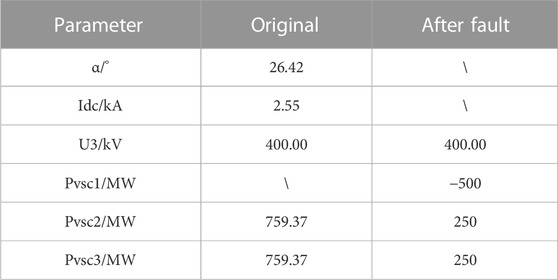
TABLE 4. Calculation results of the decision-making method in scenario 4.
Step 3: Based on the control strategy combination selected in step 1, assign the corresponding control variables according to the calculation results in step 2 to obtain the actual operating point of the system. As shown in Figure 11, the operating status of the system positive pole is displayed under the fault.
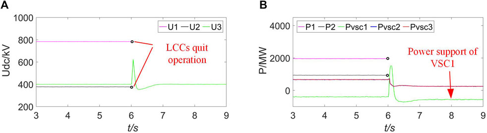
FIGURE 11. Simulation results of different operation modes in scenario 4. (A) DC voltage of each converter. (B) Active power of each converter.
The simulation results in Figure 11 indicate that when LCC2 quits operation due to a fault, calculation and decision-making methods for abnormal control can achieve the stable operation of VSCB independently after the faults in the sending end of VSCB.
4 Conclusion
This paper proposes a decision-making method that is used for flexible operation of a hybrid cascaded MTDC system. Simulation results based on PSCAD/EMTDC verify the effectiveness of the proposed method with the following contributions:
1) For normal control, a two-stage analysis method for the selection of control strategy combinations selecting the hybrid cascaded MTDC system is proposed. In the first stage, VSCs are considered VSCBs, and the control strategies of series LCCs are determined. In the second stage, station-level control strategies for VSCs are determined, which solves the problem of difficulties in decision-making.
2) The control instruction calculating method and decision-making process for normal control are proposed. According to the calculation method, under normal conditions, the control instructions are accurately calculated, and based on the decision-making process, the system can achieve precise and stable operation control of the MTDC system.
3) For abnormal control, abnormal conditions that lead to the quitting operation of converter stations are classified. A method for selecting control strategy combinations is also proposed, including three control strategy combinations, which can deal with the quitting operation of converter stations, resolving operational issues under system failure.
4) The control instruction calculating method and decision-making process for abnormal control are proposed. Under abnormal conditions, reasonable instructions for converters in bipolar MTDC systems are calculated, and the transfer of active power in the fault pole is achieved, improving the safety operation margin of the system.
Data availability statement
The raw data supporting the conclusion of this article will be made available by the authors, without undue reservation.
Author contributions
YW and ZL were responsible for conceptualization, methodology, validation, formal analysis, and writing—original draft and resources. YZ was responsible for investigation, validation, and writing—review and editing. All authors contributed to the article and approved the submitted version.
Funding
This work was supported by the National Natural Science Foundation of China under Grant 52207083.
Conflict of interest
The authors declare that the research was conducted in the absence of any commercial or financial relationships that could be construed as a potential conflict of interest.
Publisher’s note
All claims expressed in this article are solely those of the authors and do not necessarily represent those of their affiliated organizations, or those of the publisher, the editors, and the reviewers. Any product that may be evaluated in this article, or claim that may be made by its manufacturer, is not guaranteed or endorsed by the publisher.
References
Alves, E. F., Bergna, G., Brandao, D. I., and Tedeschi, E. (2020). Sufficient conditions for robust frequency stability of AC power systems. IEEE Trans. Power Syst. 36 (3), 2684–2692. doi:10.1109/tpwrs.2020.3039832
Aziz, S., Peng, J., Wang, H., and Jiang, H. (2019). ADMM-based distributed optimization of hybrid MTDC-AC grid for determining smooth operation point. IEEE Access 7, 74238–74247. doi:10.1109/access.2019.2919700
Chen, N., Zha, K., Qu, H., Li, F., Xue, Y., and Zhang, X.-P. (2022). Economy analysis of flexible LCC-HVDC systems with controllable capacitors. CSEE J. Power Energy Syst. 8, 1708–1719. doi:10.17775/CSEEJPES.2022.01620
Flourentzou, N., Agelidis, V. G., and Demetriades, G. D. (2009). VSC-based HVDC power transmission systems: an overview. IEEE Trans. Power Electron. 24 (3), 592–602. [online]. doi:10.1109/tpel.2008.2008441
Haleem, N. M., Rajapakse, A. D., Gole, A. M., and Fernando, I. T. (2019). Investigation of fault ride-through capability of hybrid VSC-LCC multi-terminal HVDC transmission systems. IEEE Trans. Power Deliv. 34 (1), 241–250. doi:10.1109/tpwrd.2018.2868467
Kwon, D.-H., Kim, Y.-J., and Moon, S.-I. (2018). Modeling and analysis of an LCC HVDC system using DC voltage control to improve transient response and short-term power transfer capability. IEEE Trans. Power Deliv. 33 (4), 1922–1933. doi:10.1109/tpwrd.2018.2805905
Li, Y., Zhao, J., Liu, H., Kong, Q., Zhao, Y., Cheng, L., et al. (2022). Adaptive droop control of the VSC-MTDC distribution network considering Power–Voltage deviation. Front. Energy Res. 9. [online]. doi:10.3389/fenrg.2021.814489
Li, Z., He, Y., Li, Y., Gu, W., Tang, Y., and Zhang, X.-P. (2019). Hybrid control strategy for AC voltage stabilization in bipolar VSC-MTDC. IEEE Trans. Power Syst. 34 (1), 129–139. doi:10.1109/tpwrs.2018.2866131
Li, Z., Wei, Z., Zhan, R., Li, Y., Tang, Y., and Zhang, X.-P. (2021a). Frequency support control method for interconnected power systems using VSC-MTDC. IEEE Trans. Power Syst. 36 (3), 2304–2313. doi:10.1109/tpwrs.2020.3026035
Li, Z., Wei, Z., Zhan, R., Li, Y., and Zhang, X.-P. (2020). System operational dispatching and scheduling strategy for hybrid cascaded multi-terminal HVDC. Int. J. Electr. Power and Energy Syst. 122, 106195. doi:10.1016/j.ijepes.2020.106195
Li, Z., Zhang, T., Wang, Y., Tang, Y., and Zhang, X.-P. (2021b). Fault self-recovering control strategy of bipolar VSC-MTDC for large-scale renewable energy integration. IEEE Trans. Power Syst. 37 (4), 3036–3047. doi:10.1109/tpwrs.2021.3127192
Liu, L., Li, H., Xue, Y., and Liu, W. (2015). Reactive power compensation and optimization strategy for grid-interactive cascaded photovoltaic systems. IEEE Trans. Power Electron. 30 (1), 188–202. doi:10.1109/tpel.2014.2333004
Rao, H., Zhou, Y., Xu, S., Cai, X., Cao, W., Xu, Y., et al. (2019). Key technologies of ultra-high voltage hybrid LCC-VSC MTDC systems. CSEE J. Power Energy Syst. 5, 365–373. doi:10.17775/CSEEJPES.2019.01140
Rao, H., Zou, C., Xu, S., Cai, X., Li, Y., Zhao, X., et al. (2022). The on-site verification of key technologies for kunbei-liuzhou-longmen hybrid multi-terminal ultra HVDC project. CSEE J. Power Energy Syst. 8 (5), 1281–1289. doi:10.17775/CSEEJPES.2022.04780
Ren, Y., Sun, H., Wang, S., Zhao, B., Xu, S., Liu, M., et al. (2023). Study on the characteristic of the grounding fault on the cascaded midpoint side of the hybrid cascaded HVDC system. Front. Energy Res. 11. [online]. doi:10.3389/fenrg.2023.1187620
Reza Ahrabi, R., Li, Y. W., and Nejabatkhah, F. (2022). Unified control of the parallel LCC-VSCs interlinking converters in a hybrid AC/DC network. IEEE Trans. Smart Grid 13 (2), 975–985. doi:10.1109/tsg.2021.3137300
Wang, R., Ma, D., Sun, Q., Sun, Q., Mu, Y., and Wang, P. (2022). Accurate current sharing and voltage regulation in hybrid wind/solar systems: an adaptive dynamic programming approach. IEEE Trans. Consumer Electron. 68 (3), 261–272. doi:10.1109/tce.2022.3181105
Wang, R., Qiuye, S., Zhang, P., Gui, Y., Qin, D., and Peng, W. (2020a). Reduced-order transfer function model of the droop-controlled inverter via Jordan continued-fraction expansion. IEEE Trans. Energy Convers. 35 (3), 1585–1595. doi:10.1109/tec.2020.2980033
Wang, T., Li, C., Mi, D., Wang, Z., and Xiang, Y. (2020b). Coordinated modulation strategy considering multi-HVDC emergency for enhancing transient stability of hybrid AC/DC power systems. CSEE J. Power Energy Syst. 6, 806–815. doi:10.17775/CSEEJPES.2019.02000
Xu, Q., Lou, J., Ning, D., and Li, P. (2023). Transient stability enhancement control through VSC-HVDC system and fast frequency response resources. Front. Energy Res. 10. [online]. doi:10.3389/fenrg.2022.1022905
Keywords: LCC-HVDC, VSC-HVDC, hybrid cascaded HVDC, MTDC, decision-making, normal control, abnormal control
Citation: Wang Y, Li Z and Zhang Y (2023) A decision-making method for the operation flexibility enhancement of hybrid cascaded MTDC. Front. Energy Res. 11:1251496. doi: 10.3389/fenrg.2023.1251496
Received: 01 July 2023; Accepted: 28 August 2023;
Published: 14 September 2023.
Edited by:
Mingfei Ban, Northeast Forestry University, ChinaReviewed by:
Feng Li, Nanjing Normal University, ChinaRui Wang, Northeastern University, China
Dongliang Xiao, South China University of Technology, China
Copyright © 2023 Wang, Li and Zhang. This is an open-access article distributed under the terms of the Creative Commons Attribution License (CC BY). The use, distribution or reproduction in other forums is permitted, provided the original author(s) and the copyright owner(s) are credited and that the original publication in this journal is cited, in accordance with accepted academic practice. No use, distribution or reproduction is permitted which does not comply with these terms.
*Correspondence: Zhou Li, lizhou1985@163.com