Visual-admittance-based model predictive control for nuclear collaborative robots
 Jun Qi
 Zhao Xu
 Jiru Chu
 Minglei Zhu
 Yunlong Teng4
- 1China Nuclear Power Engineering Co., Ltd., Beijing, China
- 2School of Automation, Chengdu University of Information Technology, Chengdu, China
- 3School of Mechanical and Electrical Engineering, University of Electronic Science and Technology of China, Chengdu, China
- 4Shenzhen Institute for Advanced Study, University of Electronic Science and Technology of China (UESTC), Shenzhen, China
This paper presents a novel visual-admittance-based model predictive control scheme to cope with the problem of vision/force control and several constraints of a nuclear collaborative robotic visual servoing system. A visual-admittance model considering the desired image feature and force command in the image feature space is proposed. Moreover, a novel constraint scheme of the model predictive control (MPC) is proposed to cancel the overshoot in the interaction force control for most cases by taking the desired force command as the constraint of the proposed MPC. Via applying the robotic dynamic image-based visual servoing (IBVS) model, some other constraints, such as the actuator saturation, joint angle, and visual limits, can be satisfied simultaneously. The simulation results for the two-degrees-of-freedom (DOF) robot manipulator with an eye-to-hand camera are present to demonstrate the effectiveness of the proposed controller.
1 Introduction
In recent years, collaborative robots have become more and more popular in the nuclear industry since the increasing need for safe and secure nuclear power plants (NPPs). Interaction between the robot and the environment or human is a fundamental requirement for the construction of NPPs 1, such as moving objects, deburring, grinding, polishing, and high-precision assembling (Nabat et al., 2005; Yang et al., 2008; Xu et al., 2017; Wu et al., 2017; Song et al., 2022, Figure 1). How to realize the precision position control and compliant interaction force control simultaneously in the nuclear environment is crucial for the execution of an interaction task.
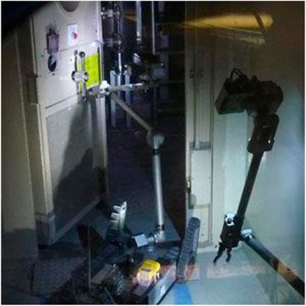
FIGURE 1. Application of collaborative robots in nuclear power plants (NPPs).
To cope with this problem, numerous force control schemes have been proposed. Two main categories of those control schemes are direct and indirect force control. Direct force control adds the feedback of the force sensor directly into the closed motion control loop. For example, in the hybrid position/force control approach, the force and position controllers work separately and are connected with a diagonal section matrix (Raibert and Craig, 1981). However, these kinds of schemes lead to a trade-off between the force controller and the position controller, which implies that neither force nor position can precisely converge to their desired target. The indirect force control includes impedance control and admittance control. They all create a mass–spring–damper (MSD) model to describe the interaction force between the robot and the environment (Mason, 1981; Hogan, 1985) and are inverse to each other. When the robot is controlled with the conventional model-based controller, precise interaction environment information and an accurate dynamic model of the robot are essential in compliant force control.
In the nuclear environment, where nuclear radiation can affect sensors and electronics, measuring accurate knowledge of the interaction environment and robot feedback is quite hard. Motivated by reducing or avoiding the need for precise preliminary knowledge of the environment, numerous researchers are trying to equip robot systems with vision and force sensors together. This method allows the robot system to get the environmental information and modify the vision/force controller online. In order to combine the visual and force information, several vision/force control schemes have been proposed to replace the motion control of the aforementioned force control with visual servoing (Bellakehal et al., 2011; Zhu et al., 2022b). For instance, in the hybrid vision/force control scheme (Zhu et al., 2022b), the force and vision are controlled separately, and a trade-off matrix is used to combine the output of two sensor controllers. Thus, these kinds of methods may result in local minima and reduce the robot control precision. In Lippiello et al. (2018), three vision-impedance controllers with the feedback of the camera and force sensor have been proposed to realize the physical interaction of a dual-arm unmanned aerial manipulator. However, the impedance control schemes can neither combine the vision and force sensing simultaneously nor avoid the trade-off between the two control loops.
To handle this problem, we propose a novel visual-admittance-based model to drive the robot with the trajectory of vision and the command of contact force. In this approach, the vision and force can be coupled in the image feature space successfully. Therefore, the convergence to a local minimum can be avoided, and the discrepancy between the modalities of vision and force sensors can be overcome.
However, due to the combination of force and vision in the image feature space, the controller is only employed to track the image feature commands generated from the aforementioned vision-admittance model without real-time perception of the contact force, which may lead to the unacceptable overshoot phenomenon and thus break the interaction environment or robot body. Therefore, we propose to consider the force command as a contact force constraint of the vision tracking controller. In practical applications, there are some other constraints on robot control systems, such as actuator saturation and visual limitation, that prevent the visual features from leaving the camera view.
Model predictive control (MPC) has been proven to be an efficient optimal control scheme aimed at addressing the disturbances and constraints of the system (Allibert et al., 2010; Deng et al., 2022). Recently, more and more researchers have concentrated on the advantages of MPC and applied this control scheme to the visual control of robots. In contrast to the aforementioned vision/force control scheme, MPC can explicitly handle the system constraints and resist disturbances. In Allibert et al. (2010), an MPC-based image-based visual servoing (IBVS) method is designed based on the conventional image Jacobian matrix and considers the constraints of image features. According to Hajiloo et al. (2016), a robust online MPC scheme based on the tensor product (TP) model of IBVS is proposed to realize the online control of MPC. By simplifying the image Jacobian matrix as a TP model, the computational speed of MPC is considerably increased. In Fusco et al. (2020b), the image feature acceleration is used to construct the model of MPC in order to get a shorter sensor trajectory and better motion in the feature space in Cartesian space. However, the aforementioned methods only consider the image feature constraints and kinematics constraints, such as the joint velocity or acceleration of the robot system, without taking into account the dynamic constraints of the robot system.
In general, in this paper, a novel visual-admittance-based MPC scheme with non-linear constraints based on the dynamic IBVS of the collaborative robot and desired force constraint is proposed to address the problem of the vision/force control with constraints. The visual-admittance model is formulated to converge the force and vision commands into image features to avoid the trade-off between two targets’ (vision and force) tracking control. Considering the overshoot of the visual-admittance model, force constraints are added to the predictive model of the MPC. Moreover, the non-linear input bounds are added to the proposed MPC based on the dynamic model of the robot.
This paper is organized as follows: in Section 2, some preliminaries of the robot dynamic model and IBVS are presented. The vision-admittance-based trajectory generator is introduced to combine the force and visual information in Section 3. Section 4 presents the MPC controller with the non-linear constraints based on the dynamic model of the robot and force constraints. In Section 5, simulations based on a robot manipulator model with an eye-to-hand camera are performed to verify the effects of the proposed control scheme. Finally, the conclusions are given in Section 6.
2 Preliminaries
2.1 Dynamic model of the robot manipulator
The dynamic model of the manipulator robot with n actuators in the task space is often described as an Euler–Lagrange second-order equation (Roy et al., 2018). When the end effector of the robot comes into contact with the environment, the environment exerts an interactive force on the robot system. Considering the external force developing from the contact between the end-effector of the robot and the environment, the dynamic model of a robot can be written as
where
2.2 Dynamic model of image-based visual servoing
Image-based visual servoing (IBVS) is a sensor-based control scheme. It uses cameras as the main sensor to estimate the pose of the robot directly.
In this work, an eye-to-hand IBVS system is established to get the visual information, and we denote the visual feature estimated by the single fixed camera as
where s = (x,y)T is the projection of p in the image space and
Differentiating Eq. 2, the relationship between the time variation of the visual feature vector
where Ls is the interaction matrix related to s (Chaumette and Hutchinson, 2006; Zhu et al., 2022a) given as
The robot spatial velocity
where cTe denotes the transform matrix from the kinematic screw to the camera frame. We define
In order to generate the actuator torque, the relationship between the image feature and acceleration of the actuator joint has been formulated in the IBVS dynamic model (Fusco et al., 2020a; Liang et al., 2022).
By differentiating Eq. 3, the second-order interaction model can be demonstrated as
When differentiating Eq. 5, we derive
where
Substituting Eqs 5, 8 into Eq. 1, the dynamic model of IBVS can be written in the following form:
where
Assumption 1: During the control process, the robot and the IBVS controller do not encounter the controller singularity (Zhu et al., 2020). J and Ls are full-rank matrices.
3 Visual-admittance-based trajectory generator
In this section, a novel visual-admittance-based (VAB) trajectory generation is proposed and used to generate a reference trajectory for the robot end-effector online with feedback from the force sensor and camera in the image feature space. The structure of the robot manipulator system with an eye-to-hand visual servoing system is given in Figure 2.

FIGURE 2. Structure of the visual-admittance-based model predictive control.
The contact dynamic model between the robot end-effector and environment is often considered a second-order MSD model in the Cartesian space (Wu et al., 2022). We assume the contact model as follows:
where ep = pr − pd represents the error between the reference trajectory and the desired trajectory of the robot end-effector in the Cartesian space. KM, KD, KS denote the positive definite impedance parameters.
Due to the intrinsic technological constraints (such as the need for certain robot intrinsic parameters), the visual/force control cannot be realized directly (Oliva et al., 2021). Therefore, the vision-admittance-based trajectory generator is designed to avoid those limits.
First, after some simple manipulations with Eq. 9, the relationship between image features and external force can be rewritten as follows:
where
where fpumi represents the vector of per unit mass/inertia (p.u.m.i) virtual forces applied on the image feature space corresponding to the robot in the Cartesian space. fu denotes the actuator torque projection in the image feature space.
Multiplying both sides of Eq. 10 by Js, the relationship between fpumi and the position error ep can be rearranged as follows:
Substituting Eqs 2, 3, 7 into Eq. 13 and denoting p = Pzs, the impedance model corresponding to the image feature can be rearranged as
where
where es = sr−sd represents the error between the reference trajectory generated from the interaction force and the desired trajectory. When the contact force of the robot is zero, sr = sd. Otherwise, the vision-based admittance model can generate the reference trajectory to perform the force control of the system.
When the system is at equilibrium, the error of the image feature acceleration will converge to zero. To simplify the admittance model and reduce the calculation complexity, we set
By solving Eq. 16, we obtain
where
Considering the desired force command
where ef = Fd − Fe, Fd is the predefined desired contact force, and Kd = diag(kd1, ⋯kdn), Kp = diag(kp1, ⋯kpn), and Ki = diag(Ki1, ⋯kin) are positive defined diagonal matrices.
4 Visual/force predictive controller
4.1 Model predictive control
MPC is an optimal control scheme proposed to solve the multi-variable constraint control problem. It determines the best input signal for a system by considering the finite future evolution of the system state. More precisely, it finds an optimal control sequence U* that minimizes a cost function Jm with a set of predefined constraints over a finite predictive horizon Np. The obtained control sequence is described as
with
which is subjected to the constraints
where
4.2 The predictive model
In this work, we choose the joint configuration, interaction force, and image features as the state vectors of MPC. This allows the controller to explicitly take the image feature and force constraints into account and handle the redundancy during the optimization process. Then, the discrete predictive model of the IBVS robot system can be described as
where Δt is the sample time of MPC and ui is the actuator acceleration at the step i. Js and J are evaluated with the change in the state vector (Allibert et al., 2010).
4.3 The joint acceleration constraints
The joint acceleration constraints aim at taking into account the physical boundaries of the actuators. Due to the interaction with the environment, it is possible that the input torque of the system exceeds the physical limit of the actuator torque, while the joint acceleration satisfies the rated acceleration constraints of the actuator. Thus, substituting the predictive state xt+i into Eq. 1, the relationship between the joint acceleration and actuator torque can be rewritten as
Then, the joint acceleration constraints of the MPC can be proposed as follows:
where i = 1, …, Np and Πt+i can be generated from the predictive state xt+i.
4.4 The terminal constraint (TC)
In this case, the stability of the proposed controller is ensured by a terminal constraint. TC imposes the last predicted visual features equal to the desired feature. However, it is difficult to satisfy a strict equality constraint when solving the optimizing problem. Thus, the constraints are converted into inequalities by defining a small enough threshold δtc.
4.5 The image feature constraints
In the context of visual serving, the image feature must remain visible. The following constraint prevents the image feature from escaping the field of the camera pixel view:
where i = 0, …, Nc − 1.
4.6 The force constraints
Considering that the possible overshoot of force control can break the interactive environment, we set the desired force as a state constraint given as
where
5 Simulation
In this section, to demonstrate the control effects of the proposed visual-admittance-based model predictive controller, several simulations are illustrated in the two-link manipulator with an eye-to-hand camera. The force sensor is inserted in the end-effector of the robot, and the robot is controlled to track the predefined force and image feature trajectory.
5.1 Simulation design
In this simulation, we choose a two-link robot manipulator as the control object of the proposed controller. The structure of the two-link robot manipulator with eye-to-hand camera configuration is given in Figure 3. The coordinate of the origin of the robot system is Pb = (0, 0, 0) m, and the dynamic model of this robot is given as
with
where,
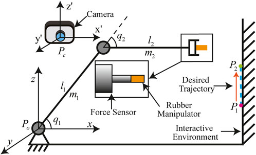
FIGURE 3. Structure of the two-link robot manipulator with eye-to-hand camera configuration.
where q1 and q2 are the joint angles of two actuators. m1 and m2 are the masses of links 1 and 2, respectively. l1 and l2 are the lengths of two links, respectively. l1c and l2c are the distances between the mass center of two links and the actuator joints, respectively. p1(0) and p2(0) are the initial joint angles. The aforementioned elements are listed in Table 1.
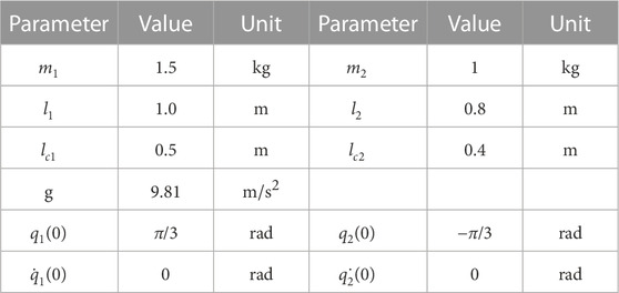
TABLE 1. Parameters and initial joint angle of the robot.
The camera set is fixed at Pc(0, 0,−2) m, and the image plane of the camera (X’OZ’) is set to be parallel to the Cartesian plane (XOZ). The camera resolution is 1280 × 720 pixels, and the focal length of the camera is 10 mm. The ratio of a pixel and unit length is 100 pixels/mm along the two axes of the pixel plane. The frequency of the camera observation is set at 50 Hz.
The constraints of actuator torque, actuator acceleration, and the image feature are, respectively, given as
In this simulation, we use Eq. 10 as the dynamic model of the force sensor. In the real interactive environment, compared with kS and KD, the value of KM is small enough to be ignored. Then, the parameters of this equation are given as KS = 10000 and KD = 0.57. The threshold of the TC is given as δtc = 100.
In the visual-admittance model, the parameters of Eq. 19 are given as Kp = 5 × 10⁻⁴, Ki = 6 × 10⁻⁴, and Kd = 2 × 10⁻⁵.
In order to validate the convergence capability and the control performance of the proposed controller, the position trajectory is predefined and consists of two phases: the approach phase and the interaction phase. The image feature trajectory we used in the MPC is generated by a virtual camera model from the position trajectory. During the approach phase, the robot needs to converge to P1, (1.5, 0.4, 0) m in 1.5 s, and in the interaction phase, the robot moves from P1 to P2, (1.5, 0.365, 0) m in 3.5 s, and the position trajectory is given as follows:
During the interaction phase, a 10 N force command is applied along the x-axis from 2 to 4 s.
In order to verify the effects of the proposed controller, three sets of controllers are introduced in this simulation to drive the robot to track the desired trajectory:
•Controller 1: The MPC we proposed in this paper. The control and prediction horizon are set at nc = 5 and np = 6, respectively, and the discretization time used in the controller is given as △t = 0.1 s. The parameters of the predictive model cost function are chosen as Kmf =, 10000, Qx = diag{1000}, and Qu = diag{0.001}.
•Controller 2: The classical MPC without the torque or interaction force constraints. The parameters of this controller are similar to Controller 1.
•Controller 3: The parallel visual and force control (PVFC) scheme proposed in Zhu et al. (2022b) with input constraints. The parameters of this controller are given as Kv = 7.5, Kp = 20, Ki = 0.01, and Kf = 0.01.
5.2 Results and analysis
In this section, to illustrate the performance of the proposed controller with the torque constraints, three controllers are investigated through the simulation on a two-DOF robot manipulator with an eye-to-hand camera. We use MATLAB to conduct the simulation and sequential quadratic programming algorithm (fmincon function in the MATLAB optimization toolbox) to solve the optimization problem of MPC. The frequency of the MPC is equal to that of the camera which is given as 50 Hz. Similarly, the frequency of the torque generator is equal to that of the joint and force sensor given as 1,000 Hz.
The image trajectories and the image errors of the three aforementioned controllers are given in Figure 4. From Figures 4A–C, we can find that the image trajectory of the IBVS system under the proposed MPC is smoother than that under the PVFC and is similar to that under the classical MPC. When the force command is applied, the overshoot of the IBVS system under the PVFC is much more serious than that of the classical MPC and proposed MPC. As is shown in Figures 4D–F, during the approach phase, the converge time of the proposed MPC (approximately 0.8 s) is shorter than that of the PVFC (approximately 1.25 s) and is very close to the classical MPC (approximately 0.75 s).
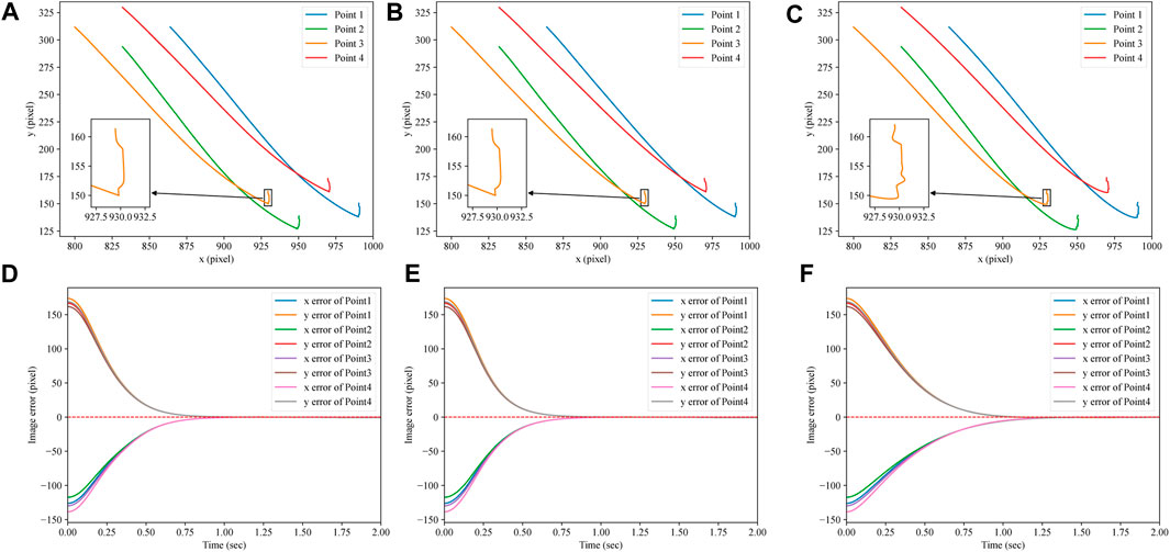
FIGURE 4. Image trajectories and errors of three controllers. (A) Image trajectory of the proposed MPC. (B) Image trajectory of the classical MPC. (C) Image trajectory of the PVFC. (D) Image errors of the proposed MPC. (E) Image errors of the classical MPC. (F) Image errors of the PVFC.
The position and force trajectories of the three aforementioned controllers are shown in Figure 5A and Figure 6, respectively. As is shown in Figure 5A, during the approach process, the length of the position trajectory in the Cartesian space under the proposed controller is shorter than that under the PVFC and, in the interaction phase, the positioning accuracy of the IBVS robot system under the proposed MPC is better than that under the PVFC. From Figures 6A, B, we can find that the overshoot and chatters of the force control in the IBVS robot system under the PVFC are the most serious within the three aforementioned controllers, and the overshoot of the force control in the IBVS system under the classical MPC still exists. Nevertheless, due to the effectiveness of the virtual interaction model and the force constraints, the overshoot and chatters of the force control in the IBVS robot system under the proposed controller are eliminated.
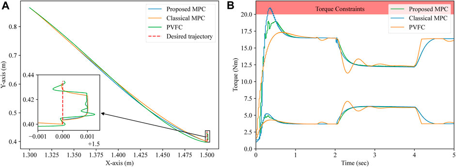
FIGURE 5. Position trajectories and input torques of three controllers. (A) Proposed and classical MPC. (B) PVFC.
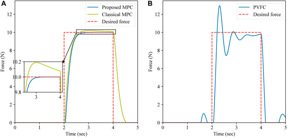
FIGURE 6. Force trajectories of the three controllers. (A) Proposed and classical MPC. (B) PVFC.
The input torques of three controllers are given in Figure 5B. The red zone in Figure 5B is the predefined torque constraint. As is shown in Figure 5B, the classical MPC without the non-linear torque constraints cannot make the IBVS system obey the torque constraints strictly, and the proposed MPC can satisfy the torque constraints. Compared with the PVFC, in the interaction phase, the input torque of the IBVS system under the proposed MPC is smoother than that under the PVFC.
6 Conclusion
In this paper, a visual-admittance-based model predictive controller is developed to cope with the overshoot and trade-off of the classical position/force control scheme in the nuclear environment. A visual-admittance-based trajectory generator is presented to combine the desired image features and the force feedback into the reference image trajectory. Considering the integration element of the visual-admittance-based trajectory generator, we propose a novel predictive model constraints scheme. In this scheme, the desired force command is considered a constraint to avoid the overshoot of the force control, and the non-linear constraints based on the dynamic model of the robot are proposed to satisfy the actuator torque limits. A torque generator is used to generate the input signal of the robot system with the proposed MPC output and the real-time feedback of the robot joint sensors. An illustrative example of a two-DOF robot manipulator with an eye-to-hand camera is given to validate the effect of the proposed control scheme. Moreover, compared with the PVFC, the proposed MPC controller has better precision in force and position tracking. Compared with the classical MPC, the proposed controller can satisfy the image feature, torque, and force constraints and eliminate the overshoot of force control.
The proposed controller still needs information about the interaction environment, such as the elements of the virtual force model in the predictive model. Our ongoing research is finding a new observer to identify the elements of the interaction environment online. In addition, simplification of the optimization process in the MPC is in progress to construct a real-time MPC scheme of the IBVS robot system with non-linear constraints. In the future, experiments will be conducted to validate the proposed method.
Data availability statement
The original contributions presented in the study are included in the article/Supplementary Material; further inquiries can be directed to the corresponding author.
Author contributions
JQ: methodology, software, validation, formal analysis, investigation, data curation, writing—original draft, and writing—review and editing. JC and ZX: validation, writing—review and editing, and data curation. MZ and YT: conceptualization, supervision, writing—review and editing, and funding acquisition. All authors contributed to the article and approved the submitted version.
Funding
This study was supported by the Natural Science Foundation of Sichuan Province (2023NSFSC0872) and the Shenzhen Science and Technology Program (CYJ20210324143004012).
Conflict of interest
Authors JQ, ZX, and JC were employed by the company China Nuclear Power Engineering Co., Ltd.
The remaining authors declare that the research was conducted in the absence of any commercial or financial relationships that could be construed as a potential conflict of interest.
Publisher’s note
All claims expressed in this article are solely those of the authors and do not necessarily represent those of their affiliated organizations, or those of the publisher, the editors, and the reviewers. Any product that may be evaluated in this article, or claim that may be made by its manufacturer, is not guaranteed or endorsed by the publisher.
References
Allibert, G., Courtial, E., and Chaumette, F. (2010). Predictive control for constrained image-based visual servoing. IEEE Trans. Robot.26, 933–939. doi:10.1109/TRO.2010.2056590
Bellakehal, S., Andreff, N., Mezouar, Y., and Tadjine, M. (2011). Vision/force control of parallel robots. Mech. Mach. Theory.46, 1376–1395. doi:10.1016/j.mechmachtheory.2011.05.010
Chaumette, F., and Hutchinson, S. (2006). Visual servo control. i. basic approaches. IEEE Robot. Autom. Mag.13, 82–90. doi:10.1109/mra.2006.250573
Deng, Y., Léchappé, V., Zhang, C., Moulay, E., Du, D., Plestan, F., et al. (2022). Designing discrete predictor-based controllers for networked control systems with time-varying delays: Application to a visual servo inverted pendulum system. IEEE/CAA J. Autom. Sin.9, 1763–1777. doi:10.1109/JAS.2021.1004249
Fusco, F., Kermorgant, O., and Martinet, P. (2020a). “A comparison of visual servoing from features velocity and acceleration interaction models,” in 2019 IEEE/RSJ International Conference on Intelligent Robots and Systems (IROS).
Fusco, F., Kermorgant, O., and Martinet, P. (2020b). Integrating features acceleration in visual predictive control. IEEE Robot. Autom. Lett.5, 5197–5204. doi:10.1109/lra.2020.3004793
Hajiloo, A., Keshmiri, M., Xie, W.-F., and Wang, T.-T. (2016). Robust online model predictive control for a constrained image-based visual servoing. IEEE Trans. Indust. Electron.63, 1–2250. doi:10.1109/TIE.2015.2510505
Hogan, N. (1985). Impedance control: An approach to manipulation: Part III—applications. J. Dyn. Syst. Meas. Control107, 17–24. doi:10.1115/1.3140701
Liang, X., Wang, H., Liu, Y.-H., You, B., Liu, Z., Jing, Z., et al. (2022). Fully uncalibrated image-based visual servoing of 2dofs planar manipulators with a fixed camera. IEEE Trans. Cybern.52, 10895–10908. doi:10.1109/TCYB.2021.3070598
Lippiello, V., Fontanelli, G. A., and Ruggiero, F. (2018). Image-based visual-impedance control of a dual-arm aerial manipulator. IEEE Robot. Autom. Lett.3, 1856–1863. doi:10.1109/lra.2018.2806091
Mariottini, G. L., Oriolo, G., and Prattichizzo, D. (2007). Image-based visual servoing for nonholonomic mobile robots using epipolar geometry. IEEE Trans. Robot.23, 87–100. doi:10.1109/TRO.2006.886842
Mason, M. T. (1981). Compliance and force control for computer controlled manipulators. IEEE Trans. Syst. Man. Cybern.11, 418–432. doi:10.1109/tsmc.1981.4308708
Nabat, V., de la O Rodriguez, M., Company, O., Krut, S., and Pierrot, F. (2005). “Par4: Very high speed parallel robot for pick-and-place,” in 2005 IEEE/RSJ International Conference on Intelligent Robots and Systems (IEEE), 553–558.
Oliva, A. A., Giordano, P. R., and Chaumette, F. (2021). A general visual-impedance framework for effectively combining vision and force sensing in feature space. IEEE Robot. Autom. Lett.6, 4441–4448. doi:10.1109/LRA.2021.3068911
Raibert, M. H., and Craig, J. J. (1981). Hybrid position/force control of manipulators. J. Dyn. Syst. Meas. Control.102, 126–133. doi:10.1115/1.3139652
Roy, S., Roy, S. B., and Kar, I. N. (2018). Adaptive–robust control of euler–Lagrange systems with linearly parametrizable uncertainty bound. IEEE Trans. Contr. Syst. Technol.26, 1842–1850. doi:10.1109/TCST.2017.2739107
Song, S., Zhu, M., Dai, X., and Gong, D. (2022). “Model-free optimal tracking control of nonlinear input-affine discrete-time systems via an iterative deterministic q-learning algorithm,” in IEEE Transactions on Neural Networks and Learning Systems, 1–14. doi:10.1109/TNNLS.2022.3178746
Wu, J., Gao, Y., Zhang, B., and Wang, L. (2017). Workspace and dynamic performance evaluation of the parallel manipulators in a spray-painting equipment. Robot. Comput. Integr. Manuf.44, 199–207. doi:10.1016/j.rcim.2016.09.002
Wu, R., Li, M., Yao, Z., Liu, W., Si, J., and Huang, H. (2022). Reinforcement learning impedance control of a robotic prosthesis to coordinate with human intact knee motion. IEEE Robot. Autom. Lett.7, 7014–7020. doi:10.1109/LRA.2022.3179420
Xu, P., Li, B., and Chueng, C.-F. (2017). “Dynamic analysis of a linear delta robot in hybrid polishing machine based on the principle of virtual work,” in 2017 18th International Conference on Advanced Robotics (ICAR) (IEEE), 379–384.
Yang, G., Chen, I.-M., Yeo, S. H., and Lin, W. (2008). “Design and analysis of a modular hybrid parallel-serial manipulator for robotised deburring applications,” in Smart devices and machines for advanced manufacturing (Springer), 167–188.
Zhu, M., Chriette, A., and Briot, S. (2020). “Control-based design of a DELTA robot,” in ROMANSY 23 - Robot Design, Dynamics and Control, Proceedings of the 23rd CISM IFToMM Symposium.
Zhu, M., Briot, S., and Chriette, A. (2022a). Sensor-based design of a delta parallel robot. Mechatronics87, 102893. doi:10.1016/j.mechatronics.2022.102893
Keywords: visual-admittance model, visual/force control, model predictive control, collaborative robot, dynamic visual servoing
Citation: Qi J, Xu Z, Chu J, Zhu M and Teng Y (2023) Visual-admittance-based model predictive control for nuclear collaborative robots. Front. Energy Res. 11:1203904. doi: 10.3389/fenrg.2023.1203904
Received: 11 April 2023; Accepted: 08 June 2023;
Published: 23 June 2023.
Edited by:
Zhi-Wei Liu, Huazhong University of Science and Technology, ChinaReviewed by:
Sahaj Saxena, Thapar Institute of Engineering & Technology, IndiaTiedong Ma, Chongqing University, China
Ruizhuo Song, University of Science and Technology Beijing, China
Copyright © 2023 Qi, Xu, Chu, Zhu and Teng. This is an open-access article distributed under the terms of the Creative Commons Attribution License (CC BY). The use, distribution or reproduction in other forums is permitted, provided the original author(s) and the copyright owner(s) are credited and that the original publication in this journal is cited, in accordance with accepted academic practice. No use, distribution or reproduction is permitted which does not comply with these terms.
*Correspondence: Jiru Chu, chujr@cnpe.cc