Research on multi-energy cooperative participation of grid frequency inertia response control strategy for energy storage type doubly-fed wind turbine considering wind speed disturbance
 Dongyang Sun
 Fanqi Zhao2
  Jixuan Yu
- 1School of Electrical and Electronic Engineering, Harbin University of Science and Technology, Harbin, China
- 2Marine Design and Research Institute of China, Shanghai, China
With the proposal of carbon peaking and carbon neutralization, the penetration rate of wind power generation continues to increase. This paper focuses on the problem that doubly fed induction wind turbines are vulnerable to input “source” disturbances and have weak frequency modulation ability, which reduces the stability of the power grid. Based on the structural model of energy storage system embedded in doubly fed wind power generation system, it is compared the ability of super capacitor energy storage and releasing rotor kinetic energy to provide inertia response power and energy, and the feasibility of multi-energy coordinated inertia response is analyzed. Based on the inertia time constant of conventional synchronous generator set, the inertia time constant and actual inertia constant of energy storage doubly fed wind power generation system under variable wind speed are defined. An extended state observer is used to estimate the change of captured mechanical power caused by the change of wind speed, and a control strategy for doubly fed induction generator with super capacitor to participate in power grid frequency regulation is designed. Finally, considering the aggregation of wind power and the difference of the state of charge during the operation of distributed energy storage, the 3*3*3 wind farm model is established using Matlab/Simulink simulation software. The feasibility and advantages of the frequency modulation control strategy proposed in this paper are verified by building a power grid frequency modulation simulation involving wind farms and traditional generators.
1 Introduction
At the 75th UN General Assembly, China proposed to strive to peak carbon dioxide emissions by 2030 (Li et al., 2021a; Xin, Shan, Li). To solve the contradiction between energy demand and carbon emissions, global wind power generation will reach 3.8 TW and the wind power generation of China will account for more than 50% (Sun et al., 2021). This change will change the dominant position of conventional synchronous machine power supply. With the rapid development of UHV(ultra high voltage) transmission and the widespread application of power electronic converter equipment at the distribution side (Xie et al., 2021). The “double high” characteristic will become more prominent and become an important technical feature of the new generation of power systems (Yuan et al., 2016). Double fed induction generator (DFIG), as one of the mainstream wind turbines (Li et al., 2022), decouples the rotor speed from the grid frequency during grid connected power generation, resulting in poor inertia response of the system. Therefore, how to enhance the ability of DFIG to participate in the power grid frequency modulation is a great significance for the stable operation of power grid (Tan et al., 2015; Peng et al., 2019).
Most of the existing studies on enhancing the inertia response ability of wind turbines focus on generator rotor control or additional energy storage device to improve the inertia response ability of DFIG. For generator rotor control, there are two methods commonly adopted (Kang et al., 2016; Liu et al., 2017; Altin et al., 2018; Chu et al., 2020; Li et al., 2021b; Xu and Wang, 2021; Si et al., 2022), one is to increase the electromagnetic torque to obtain additional instantaneous power to provide inertia response for system frequency modulation. The essence of this control method is to release the kinetic energy of the blade rotor to compensate for the energy imbalance when the grid frequency fluctuates. In literature (Xu and Wang, 2021), an improved torque limit-based inertial control (TLBIC) based on torque limits is proposed, when the system frequency changes, DFIG rapidly increases the active reference power to the torque limit and then smoothly decreases to the maximum power point tracking (MPPT) curve by exponential function. Improve frequency nadir by releasing less kinetic energy, while ensuring rapid frequency stabilization and reducing second frequency drop. In literature (Li et al., 2021b), a fuzzy adaptive control method for virtual inertia of wind turbines based on frequency response interval division is proposed. With the rapid change of damping frequency, the system frequency recovery is accelerated, and the rational distribution of finite rotor kinetic energy in the process of system frequency response is realized. In literature (Chu et al., 2020), a new inertia control strategy for wind turbines is proposed, which eliminates the influence of secondary frequency drop, and integrates the analysis of inertia dynamic characteristics of wind turbines into the frequency dynamic characteristics of the system. Literature (Altin et al., 2018) considers that the fixed design method of wind turbines with different sizes may cause the wind turbines to produce excessive inertia response in some cases. Therefore, it is necessary to study the optimal inertia response energy released in the same wind speed range. Literature (Liu et al., 2017) based on the study of traditional virtual inertia and short-term release of rotor kinetic energy method, an improved control method is proposed to achieve a proper balance between preventing frequency drop twice and restoring speed. In literature (Kang et al., 2016), a method of releasing rotor kinetic energy suitable for DFIG is proposed. In the early stage of inertia response, the release of kinetic energy is limited by the maximum torque to achieve the best inertia response effect. When exiting, the recovery speed of the rotor is slowed down to avoid a serious secondary drop in the grid frequency. However, it is still proposed in the literature that the problem of power grid frequency secondary drop will exist no matter how to optimize.
For this reason, some studies propose to change its maximum power point tracking (MPPT) curve and obtain power margin through over speed load shedding, which can avoid the second drop of the power grid. In literature (Si et al., 2022), it is suggested an enhanced primary frequency response strategy of a doubly-fed induction generator in association with pitch angle control. The DFIG works in de-loaded operation with a certain reserve power via pitch angle control prior to disturbances for frequency regulation. In literature (Ochoa and Martinez, 2016), for large-scale wind power systems, a simplified model of wind turbine is proposed to analyze the system frequency dynamic characteristics. Based on the function of grid frequency deviation and its time derivative, the virtual inertial controller of optimized power point tracking (OPPT) method is designed, and the instantaneous active power of the system is changed by changing the maximum power point tracking curve.
However, changing the optimal power curve of the wind farm will lead to the reduction of the sustainable power generation of the wind farm. Therefore, some studies suggest that additional energy storage devices (batteries, super capacitors, super conducting energy storage, flywheel energy storage, etc.) can be used to improve the inertia response capability of DFIG. Literature (Anping et al., 2018) starting from the inertial characteristics of macroscopic objects in the inertial reference frame, the concepts of electric potential energy and magnetic field energy inertia are introduced and their characterization methods are given based on the physical viewpoint that inertia is an inherent property of energy. According to the law of energy conservation, the calculation method of the equivalent moment of inertia of electric potential energy and magnetic field energy is given. Taking the power battery energy storage system as an example, the calculation method of the equivalent moment of inertia of the energy storage battery body and the energy storage converter is demonstrated. In literature (Yoo et al., 2019), the influence of energy storage on different parameters in power grid frequency modulation is analyzed, and the optimal method of control parameters of energy storage system with the increase of wind farm permeability is designed. In literature (Liu et al., 2015), the virtual inertia of the wind energy storage system is defined, and the capacity requirements of the energy storage device to assist the wind farm to compensate for the inertia is studied. Based on the fuzzy logic control, a control strategy using the energy storage device to compensate the inertia of the wind farm is proposed. In literature (Zhu et al., 2017), an integrated inertia control strategy for wind turbines based on DFIG is proposed. In the proposed scheme, Li-ion super capacitors are added to the DC link of the power electronics conversion system of the DFIG generator to increase additional energy storage capacity and minimize the maximum frequency deviation under specific operating conditions. In literature (Miao et al., 2015; Musarrat et al., 2018), superconducting energy storage is applied to wind power frequency modulation control and rotor speed recovery to enhance the inertia response ability of wind storage system. In literature (Liang et al., 2020), on the basis of variable proportional coefficient speed regulation and flywheel energy storage to achieve frequency support, a two-layer cooperative control scheme of flywheel energy storage and MPPT operating wind turbine to provide frequency response is proposed based on the theory of cooperative control. In literature (Miao et al., 2015), a coordinated control strategy based on wind turbine and energy storage system is proposed to compensate the inertia of wind farm, which can improve the temporary frequency support of wind turbine and overcome the problems of system frequency oscillation and secondary frequency drop. In literature (Choi et al., 2016), a hybrid operation strategy based on wind turbine and energy storage device is proposed. The wind turbine abandons the maximum wind energy tracking curve to obtain power margin, and the energy storage device adjusts the short-term frequency response by fast charging and discharging to ensure the stable operation of the power system.
For DFIG to participate in instantaneous frequency modulation of power grid, it is necessary to ensure both instantaneous power and energy balance in the whole frequency modulation process. This paper completes the following:
1) Firstly, A single-machine frequency modulation control method combining super capacitor and doubly-fed wind turbine is adopted. This Architecture is called SCESS-DFIG in this paper. Based on the energy-power perspective, the inertia response capability of the single-machine energy-storage DF2) IG at different speeds is studied, and the instantaneous adjustable range of the energy-storage DFIG at different speeds is determined. According to the research results, the method of multi-energy sources (rotor kinetic energy and energy storage) cooperatively controlling and participating in the frequency modulation of the power grid is more feasible.
2) Secondly, considering the instantaneous influence of wind speed variation on inertia response, the inertia time constant of energy storage DFIG under variable wind speed is defined. The influence of wind speed change on the inertia response of the fan is classified into “inertia, over inertia, negative inertia” according to the effect of the influence. The inertia response capacity configuration of SCESS-DFIG is determined by considering wind disturbance.
3) An expanded state observer (ESO) is established to estimate the instantaneous mechanical energy change captured by the wind turbine, and a multi-energy cooperative control strategy based on energy storage is designed using the estimated value and the state of charge (SOC) of the energy storage device. The control strategy can rationally utilize or suppress the influence of wind speed variation, and enhance the inertia response ability of energy-storing DFIG. Matlab/Simulink was used to build the frequency modulation simulation of the energy-storage DFIG to verify the proposed control strategy.
2 Analysis of economy and operation characteristics of SCESS-DFIG
2.1 Architecture and economic analysis of super capacitor energy storage in wind power frequency modulation control
The topology of super capacitor combined with DFIG is shown in Figure 1. It is mainly divided into (a) Centralized energy storage power station and wind farm architecture; (b) Distributed SCESS-DFIG architecture. Compared with the architecture adopted in Figure 1, the energy-storage DFIG architecture shown in Figure 1 has the following advantages:
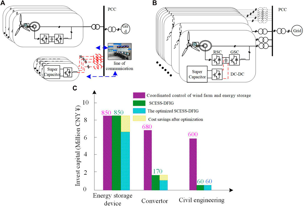
FIGURE 1. Architecture of energy storage system participating in wind farm power regulation and economic comparison between them.
Economic analysis of super capacitor energy storage system: In the process of DFIG operation, the instantaneous power of the grid-side converter is related to the mechanical power captured by the wind turbine, and it does not operate at full load in real time. Therefore, the spare capacity of the grid-side converter (GSC) of DFIG can be used to replace the AC-DC converter in the traditional super capacitor energy storage system. This design can greatly optimize the economy of energy storage device assisting wind power system in participating in power grid frequency modulation. According to (Sun et al., 2019; Yan et al., 2020), the summary and topology analysis are summarized. Figure 1 and Figure 1 shows the comparison of investment in cooperative frequency modulation between wind power plants (100 MW, cost about 760 million CNY¥) and energy storage systems (8 MW × 30 min) under different architectures. If the architecture as shown in Figure 1 is adopted, the wind farm needs to invest about 21.3 million CNY¥ for the configuration of the energy storage system, including the energy storage device, grid-connected inverter, DC-DC converter, basic field construction, communication system and other configuration costs. However, the energy storage DFIG architecture as shown in Figure 1 reduces the converter investment by about 5.1 million CNY¥, which is about 15.96% of the total investment of the energy storage power station.
Optimize the economy of civil engineering, communication system and other supporting facilities: as shown in Figure 1, the investment costs required under different combined wind storage architectures are summarized according to (Sun et al., 2019; Yan et al., 2020). Since each doubly-fed wind turbine has an independent energy storage device, the DC converter control circuit and dual PWM control circuit can be integrated in a single control board to achieve a highly integrated design of wind storage control. At the same time, the energy storage type DFIG can be installed inside the wind turbine without additional infrastructure land, which saves about 25.35% of the total system investment (about 5.4 million ¥).
In addition, as shown in the third column of Figure 1, the generator set with energy-storage DFIG architecture can adjust the control strategy according to its own situation, coordinate the energy relationship between the rotor kinetic energy and the super capacitor energy storage, and improve the energy utilization rate and service life of the super capacitor energy storage device. This can further optimize the economy of frequency modulation of the system. Thus, for a wind farm with 100 MW capacity, the architecture of energy-storage DFIG can save 41.16% of the energy storage system cost.
For a power generation system, it is necessary to solve the problem of system performance while considering the economy. In the following, studies will be conducted to ensure that the system has the ability of frequency modulation under full working conditions, coordinate the distribution of the kinetic energy of the wind turbine rotor and the weight of the energy storage system, and enhance the stability of the system and optimize the energy utilization efficiency while suppressing the influence of wind speed.
2.2 Analysis of inertia response capacity of SCESS-DFIG
There are two main energy sources for SCESS-DFIG to participate in power grid frequency modulation: mechanical energy (kinetic energy of wind turbine blades or wind energy captured by load shedding) and electric energy (energy stored by super capacitor). The former can extract additional rotor kinetic energy by controlling the rotor-side converter (RSC) power. Its advantage is that it has a faster response speed and does not need to be configured with additional equipment. However, the disadvantages are also obvious. If the kinetic energy of the blade is released in a long time scale, the wind energy captured by the wind turbine will be reduced, which is easy to cause the second drop in the grid frequency. Super capacitor energy storage can provide stable frequency modulation energy and enhance the inertia response ability of wind turbines. However, its response ability is not only affected by the capacity of the energy storage device configured, but also by the capacity of the converter and GSC configured. The following will analyze the inertia response capability of the two turbines at different speeds from the perspectives of energy and power.
2.2.1 Analysis of inertia response capacity based on power angle
As shown in Figure 2, the inertia response capability provided by rotor kinetic energy control and energy storage is compared respectively. Figure 2 shows the 3D diagram when the inertia time constant H is three and the rotor kinetic energy is released by control to provide the inertia response energy under different slip rates and wind speed variation. It can be seen from the figure that the higher the rotor speed is, the greater the inertia response power can be provided instantaneously through the rotor kinetic energy. Figure 2 shows the inertia response power provided by the super capacitor under different slip rates and wind speed variations. When the value of slip is very small, the GSC absorbs power, and the maximum instantaneous theoretical release power of the super capacitor is close to the rated power two times. As the rotor speed increases, the DFIG shifts from the sub-synchronous speed condition to the super-synchronous speed condition, and the instantaneous theoretical maximum released power of the super capacitor decreases continuously.
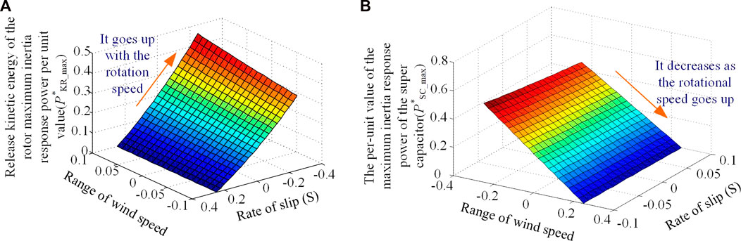
FIGURE 2. Investment cost under different wind storage coordination structures.
The range of instantaneous output power PSD of SCESS-DFIG is:
Where, ωs is the stator angular velocity, ωm is the angular velocity of the DFIG rotor, ω Max is the highest speed of DFIG, PDFIG is the instantaneous power of DFIG, and PDFIG_N is the rated power of DFIG. Eq. 1 is not only applicable to the sub-synchronous speed, but also to the synchronous and super-synchronous speed. Simplification 1) can be rewritten as shown in Eq. 2. If energy storage is considered to have sufficient capacity, the power range of energy-storing DFIG is essentially only related to rotor speed.
The relationship between the output power of doubly-fed wind turbine and rotor speed at different speeds:
kopt is the proportional coefficient of the maximum power tracking curve; ω1 is the angular velocity of cutting in; ω2 is the electric angular velocity when entering the constant speed zone; ω3 is the electric angular velocity when entering the constant power region. Substitute 2) into 3) to obtain the power operating range of SCESS-DFIG under full working conditions.
The instantaneous power expression of SCESS-DFIG in [ω1, ω2] region is:
The instantaneous power expression of SCESS-DFIG in [ω2, ω3] region is:
Thus, the maximum power range of the super capacitor can be obtained: In the region [ω1, ω2], the maximum value of the power released and absorbed by the super capacitor is:
In the region [ω2, ω3], the maximum value of the power by the super capacitor is:
As shown in Figure 3, power curve comparison between DFIG and SCESS-DFIG under full working conditions can be obtained according to Eqs 3–7. The upper area of the DFIG power curve represents the power range released by the super capacitor, and the lower area represents the power range absorbed by the super capacitor.
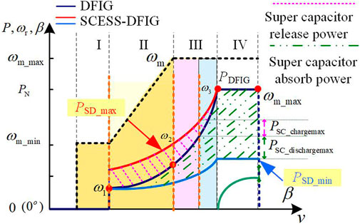
FIGURE 3. Comparison of DFIG and Energy storage type DFIG power operation under full operating conditions.
2.2.2 Comparative analysis of inertia response capacity of different energy sources based on energy
Figure 4 shows the rotor speed or the number of super capacitor modules required when the active release of rotor kinetic energy and the super capacitor energy storage system have different inertia response constants under different wind speed variations. The parameters used in this paper are given in the Appendix. Figure 4 shows that if the inertia response energy is provided only by the rotor kinetic energy, the rotor speed needs to reach 2000 rpm when the inertia time constant H = 3, which is already beyond its maximum operating speed for the two-pair motor. As can be seen from Figure 4, with the increase in the number of super capacitor modules, the energy possessed by the super capacitor increases continuously.
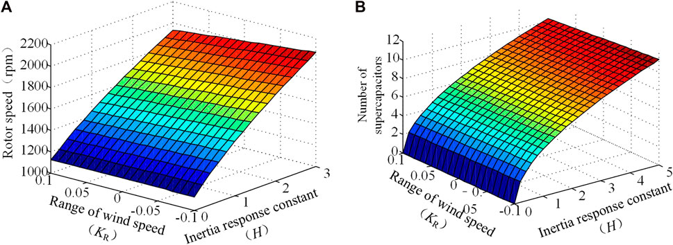
FIGURE 4. Minimum speed or number of modules required for inertia response constants of different methods.
The theoretical analysis in this section shows that the kinetic energy of the blade released by active control and the energy of the super capacitor can be complementary at different speeds. The energy demand of the super capacitor can be reduced through reasonable coordinated control without reducing the economy of the doubly-fed wind turbine under normal conditions.
3 Grid frequency inertia response control with SCESS-DFIG considering wind speed variation
3.1 Definition of SCESS-DFIG inertia time constants taking into account wind speed variation.
The inertia time constant H is usually used to represent the influence of the inertia on the dynamic behavior of grid-connected generator sets. For the doubly fed induction generator, the inertia time constant H is described as shown in Eq 8:
EK is the kinetic energy stored in the rotor of the simulated synchronous generator at rated speed.
Theoretically, according to (8), the equivalent inertia time constant HSD_N of SCESS-DFIG under wind speed change can be defined as:
The ESD is the total inertia response energy of SCESS-DFIG, ESC is the energy of inertia response provided by the super capacitor, EKR is the kinetic energy of DFIG blade, △Ewind is the energy change of DFIG system caused by wind speed change. Hsc is the equivalent inertial time constant of the super capacitor, HKR is the equivalent inertia time constant of kinetic energy of DFIG rotor, Hwind is the equivalent inertia time constant of wind speed change. However, HSD_N is the maximum value of inertia time constant of the wind turbine with energy storage in theory, but absorbing the kinetic energy of the wind turbine rotor will temporarily improve the inertia response ability of the system, but it is easy to cause the second drop of the grid frequency.
The expression of super capacitor energy in Eq 9 can be expressed as follows:
USC_N is the rated voltage of the super capacitor.
The expression of rotor kinetic energy in Eq. 11 can be expressed as follows:
JDFIG is the virtual equivalent moment of inertia of SCESS-DFIG, ΩDFIG is the initial mechanical angular velocity of DFIG blade.
In the actual operation process, Eqs 10, 11 can be rewritten as the following:
USC is the initial voltage of the super capacitor, and USC_min is the minimum voltage threshold of the super capacitor.
ΩDFIG_min is the lowest threshold of the mechanical angular velocity of the DFIG blade. Ω△w is the change of mechanical angular velocity of the blade under the influence of wind speed in the process of inertia response.
For energy storage, the maximum charging energy of the super capacitor E'SC_chargemax and the maximum discharging energy E'SC_chargemax can be written as:
Therefore, the adjustment range of inertia time constant of energy storage in the system can be set as [H'SC_min, H'SC_max], and the expression is as follows:
Assuming that the inertia response time is t, the change of energy at the “source” side due to the change of wind speed in the process of inertia response is shown in Eq. 16:
Where, △Pmppt is the change of generator output power。
According to Eqs 12–16, the inertia response constant H'SD of the SCESS-DFIG can be redefined as follows:
E'SD is the total energy of inertial response provided by energy storage DFIG, E'SC is the energy of inertial response provided by energy storage, E'KR is the kinetic energy provided by DFIG blades, and △E’wind is the energy change caused by wind speed change to DFIG system. H’sc is the actual equivalent inertia time constant of the super capacitor, H'KR is the actual equivalent inertia time constant of DFIG rotor kinetic energy, and H’wind is the actual equivalent inertia time constant of wind speed change.
In order to enable SCESS-DFIG to have rotational inertia like traditional synchronous generator sets, the relation of its inertia time constant HSD is as follows:
J'SD represents the virtual equivalent moment of inertia of DFIG with actual energy storage.
The inertial response power ΔPSD can be obtained through Eq. 18:
ωg is the electrical angular velocity of the power grid.
According to Eq 19, HSD can be written in a form related to the virtual moment of inertia JSD and the rated grid angular velocity ωgN:
Substituting Eq. 20 into Eq. 19, the relationship between the ratio of inertia response power of SCESS-DFIG and its rated generation capacity, inertia time constant and the unit value of the change rate of electrical angular frequency of the power grid can be obtained after sorting:
After sorting, the relations between the inertia response power unit value
3.2 Influence analysis of wind speed variation on SCESS-DFIG inertia response
State Grid Corporation points out in “Technical Regulations on Wind Farm Access to Power System” that wind farms should have the ability to regulate active power, and stipulates that the change of active power cannot exceed the regulations when wind farms are connected to the power system. This makes the influence of wind speed variation on inertia response reliable. The maximum change of active power of wind farm in 1 min is about 10% of the rated capacity of wind farm, while the time scale of inertia response is lower than 1 min. In this paper, it is assumed that the power change during the inertial response does not exceed 10% of the rated power (GB/T 19963–2011, 2011).
As shown in Figure 5, the 40 wind generators are divided into eight groups, the curves of mechanical power and electromagnetic power captured by a single DFIG and the whole DFIG are given under different random wind speeds. It is not difficult to find from Figure 5 and Figure 5 that the random wind speed has an impact on the captured mechanical power of the wind turbine and the electric energy output of the system. Due to the moment of inertia of the blades, the latter has a certain lag filtering effect compared with the former. By analyzing Figure 5, it can be seen that the overall power of the wind farm is also affected by the change of wind speed. Although multiple units have aggregation effect, the overall output power will still fluctuate. If the grid frequency drop occurs at 2 s, the power fluctuation caused by the 2 s–10 s wind speed change in Figure 5 can be divided into three regions. In region 1, the wind farm power increases with the wind speed change, which plays a positive inertia response to the grid frequency, which is beneficial to the grid stability control. In the process of wind speed variation from 5.5 s to 8. 5 s, the output power of the wind farm is lower than the initial time of frequency modulation, which plays a negative inertia response to the frequency variation of the power grid, aggravating the power frequency imbalance and power sag of the power grid, which is harmful to the stability control of the power grid. As shown in Figure 5, the output power of the wind farm increases after 8.5 s, and the frequency change rate of the power grid is low at this time, and the power change of the wind farm is easy to cause over-inertia response.
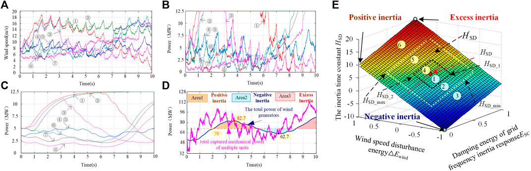
FIGURE 5. The curves of captured mechanical power and generated power of single machine and wind farm under different wind speeds and the influence of wind speed variation on inertia response.
The essence of SCESS-DFIG simulating the inertia response characteristics of conventional generator sets is to virtual a moment of inertia, which is not only a rotating body with mass, but the moment of inertia coupling its kinetic energy with the frequency of the power grid. When simulating the virtual moment of inertia, as shown in Eq. 8, when other parameters are fixed, the kinetic energy determined by the moment of inertia is associated with the inertia constant. As can be seen from the description in the previous section, H can be regarded as a time, that is, the time for continuously providing the inertia response power. However, according to (18), it can be concluded that the magnitude of the inertia time constant will also have an impact on the magnitude of the instantaneous inertia response power. For a conventional generator set, its moment of inertia is fixed, and its moment of inertia time constant H is also fixed. As a result, both the instantaneous inertia response power and the inertia response duration of the conventional generator set are passive and unadjustable. However, the SCESS-DFIG can separate the two, that is, the instantaneous inertia response power and duration can be adjusted, and to a certain extent, the mutual constraints of the two can be avoided. As shown in Figure 5, the influence of wind speed variation on fan inertia response is classified into “inertia, excess inertia and negative inertia” according to the effect of the influence.
3.3 Analysis of inertia response capacity allocation in SCESS-DFIG
In engineering practice, when energy-storing DFIG participates in the process of power grid frequency adjustment, the power grid frequency can only be in a limited area fmin to fmax. fmin with the fmax is different from 50 Hz about 2–3 Hz. It is expected that SCESS-DFIG has the same virtual moment of inertia as the traditional generator. For an ultra-short time scale, the instantaneous release power increment and periodic energy increment of SCESS-DFIG are the same as those of the simulated conventional generator, which means that they have the same inertia effect on the frequency support of the power grid. Therefore, the energy storage system taking into account wind disturbance should be theoretically analyzed in terms of power and energy.
3.3.1 Theoretical analysis of inertia response power capacity considering wind disturbance
In order to obtain the typical value of instantaneous power, a comparative analysis between TJ, HSD_s and △t is required. It can be considered that the time for wind power to participate in inertia response relying on SCESS-DFIG is equal to that. SCESS-DFIG provides the power capacity of frequency inertia response is:
In the actual operation process, it is affected by the change of wind speed. The average active power △PSD_a of SCESS-DFIG participating in the inertial response process of the system is shown in Eq. 24:
Therefore,H'SD should be controlled in the actual control to make the system output power close to the typical value △PSD, as shown in Eq. 25:
3.3.2 Energy matching analysis of inertia response to wind disturbance
The maximum rotor kinetic energy that can be released by the synchronous generator during the inertial response is:
When the generator is operating at rated speed, the kinetic energy stored in the rotor will be released during △t when the grid frequency drops to the lowest value f*min as follows:
According to the above analysis, in the process of inertial response, if SCESS-DFIG releases the same energy as the synchronous generator, △ESD = △ESG_K, and the performance of inertia response in the energy perspective is similar. It is assumed that the time for the wind farm to participate in the inertial response of the system by relying on energy storage is consistent with the inertial time constant of synchronous power generation, namely TJ = 2HSD = △t. The typical value of inertia response energy matching in SCESS-DFIG can be represented by Eq. 28:
The actual operation process is affected by the change of wind speed. The energy of energy-storing DFIG participating in the inertial response process of the system is △ESD_a, as shown in Eq. 29:
In the actual control, the system should control H'SD so that the inertia response energy provided by the system is close to the typical value △ESD, which is shown in Eq. 30:
In the actual operation control process, considering the compensation of the effect of the wind speed change and the regulation of H'SD, it is necessary to grasp the real-time mechanical power captured by the fan. In the next section, the expanded state observer (ESO) will be established through the equation of motion of DFIG to estimate the instantaneous captured power of the wind turbine.
4 Optimal control strategy of grid frequency inertia response based on SCESS- DFIG considering wind speed variation
4.1 Mechanical power estimation of fan capture based on ESO
The influence of wind speed and torque limit are taken into account in the above section. Considering the torque constraint of mechanical structure, the instantaneous captured mechanical power of wind turbine needs to be estimated and applied to the control strategy. Based on the traditional observer, ESO expands the total disturbance affecting the controlled output of the system into a new state variable, and then estimates the state variable and the total disturbance of the system (Liu et al., 2016; Zhao and Guo, 2017).
Considering a class of uncertain non-linear dynamic systems shown in Eq. 31:
Where x is a state variable;
xn is a dilated state that quantifies the effect of perturbations on the system. Considering the interaction between states and perturbations in a single extended dynamic system, an ESO can be established for Eq. 32 as shown in Eq. 33 below.
Where,
The expression of the function
As the wind energy captured by the wind turbine is an internal state quantity, it cannot be directly sampled and measured by the sensor. The rotor speed of the variable related to the captured mechanical power of the wind turbine is controlled digitally by the encoder sampling output signal, which is easy to cause interference to affect the differential value of the speed dωm/dt, and the captured mechanical power cannot be calculated directly according to the dynamic equation. The purpose of using ESO in this paper is to estimate the real-time state of the input mechanical power of the wind turbine only according to the dynamic response characteristics of the generator without passing the dωm/dt of the rotor speed, and the estimation result is used as a control input for the inertia response control of the SCESS-DFIG.
Since (38) is a non-linear differential equation, it cannot be directly estimated by using the expanded state observer, so it is necessary to transform the differential of speed and speed into the form with only the differential of speed:
After finishing, it can be rewritten as the standard first-order differential form about ω2m:
The wind captured power and the mechanical loss power are combined into PSD_M, which is the actual input mechanical power of the generator. After expanding the state of ω2m Eq. 38 is obtained:
Set z1 in Eq. 38 as ω2m, the dilated state (interference) z2 = PSD_M/JDFIG, input u1 = PSD_es + PSD_rsc, input coefficient b1 = −1/JDFIG, thus the dilated state observer can be constructed as follows:
Where
In the process of estimating the input mechanical power PSD_M by the extended observer, the required parameters mainly include JDFIG, ωm, stator side power Pes and RSC power PSD_rsc. JDFIG is intrinsic parameters, the rest of the variables can be after speed, voltage, current sensor detection through simple to calculate, this makes the extended state observer for implementation, and can not through the generator differential mid-value directly estimate the rotational speed of the motor input mechanical power, enhance the anti-interference ability of the system of measurement noise.
As shown in Figure 6, after accurately estimating the input mechanical power of the starting motor by ESO, it can be used as a reference for the control of the output power of the generator.
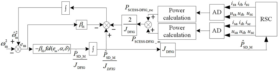
FIGURE 6. The working principle of the ESO for the mechanical power estimation.
Therefore, the constant value of inertia time caused by wind speed change in Eq. 16 can be rewritten as follows:
4.2 Optimal control strategy of grid frequency inertia response based on energy storage DFIG considering wind speed variation
As shown in Figure 7, when the capacity configured by the super capacitor and the kinetic energy of the rotor are different, the capability of providing inertia response is different. The inertia time constants can be divided into[HSD_min, HSD_1], [HSD_1,HSD], [HSD,HSD_2], [HSD_2,HSD_max] according to the frequency regulation ability. In the actual control process, according to H’sc、H’wind、H'KR of the actual state regulation system H'SD, the system has better inertia response ability under the operating wind speed.
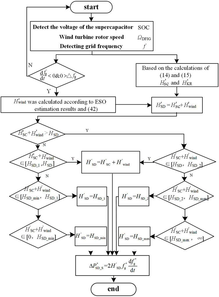
FIGURE 7. Power control flow chart of inertia response based on actual system running state.
As shown in Figure 7, the system states can be divided into six types according to the four regions, and the operation strategies of each state are explained below. Among them, ①∼③ is the inertia response control strategy under the condition of wind speed decline,①when (H’sc + H’wind) in [HSD_1, HSD], the overall inertia time constant of the system is within a reasonable range, so kinetic energy of the blade does not need to be absorbed in this region, and the actual inertia time constant of SCESS-DFIG is H'SD = H’sc + H’wind and H'KR = 0; ② (H’sc + H’wind) in [HSD_min, HSD_1], the system is in the weak inertia characteristic due to the influence of wind speed. At this time, relying only on energy storage cannot provide reliable inertia response. Therefore, in order to avoid deviation from the MPPT curve, only part of the rotor kinetic energy is absorbed to make H'SD = HSD_1; ③ (H’sc + H’wind) less than Hmin, the system is in the characteristic of strong and weak inertia. In this case, the system needs to release all the stored energy (energy storage and rotor kinetic energy) to make the system inertia time constant H'SD = Hmin, so that the system can provide the inertia response support required by the load system under the influence of wind speed. ③ (H’sc + H’wind) less than Hmin, the system is in the characteristic of extremely weak inertia. In this case, the system needs to release all the stored energy.
(energy storage and rotor kinetic energy) to make the system inertia time constant H'SD = Hmin, so that the system can provide the inertia response support required by the load system under the influence of wind speed. ④∼⑥ is the inertia response control strategy when the wind speed rises. ④(H’sc + H’wind) in [HSD,HSD_2], the overall inertia time constant of the system is in a reasonable range, so kinetic energy of the blade does not need to be absorbed in this region, and the actual inertia time constant of SCESS-DFIG should be H'SD = H’sc + H’wind and H'KR = 0; ⑤when (H’sc + H’wind) in [HSD_2,HSD_max], the system is in the extremely inertia characteristic. At this time, the system needs to depend on energy storage to adjust H’sc to make system H'SD = HSD_2. ⑥. When the (H’sc + H’wind) greater than HSD_max, the sudden rise of wind speed makes the system have too strong inertia response, and in this case, it still needs to rely on H’sc and H'KR to make system H'SD = Hmax.
Figure 8 shows the control block diagram of the rotor-side converter and the DC-DC converter of the super capacitor in the SCESS-DFIG power generation system. In the figure, the sampling points and sampling quantities of the system are marked. The instantaneous power commands of the super capacitor and DFIG are obtained through the above flow chart and given to the RSC and DC-DC converters, respectively, so that the system can complete the frequency modulation control.
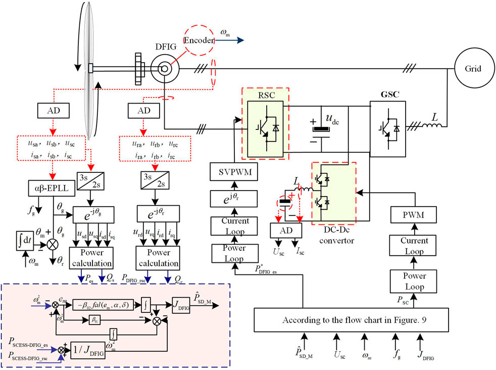
FIGURE 8. Control block diagram of RSC and DC-DC converter in SCESS-DFIG.
5 The simulation verification
Figure 9 is inertia response simulation model architecture of SCESS-DFIG with variable wind speed. The simulation model shown in Figure 12 mainly includes wind farm (27 units with rated power of 2.5 MW the states and working conditions of different DFIG are shown in Table A1), synchronous generator (rated power of 220 MW), and conventional load L1, sudden load L2. The model of the wind farm includes the parameters given by different wind speed changes, rotor speed and super capacitor SOC. The initial rotor speed is divided into low, medium, high wind speeds. The influence of wind speed change is rising (positive inertia), steady (no influence) and falling (negative inertia). The super capacitor SOC is high (100%), medium (85%) and low (70%). A 3 × 3 × 3 simulation model of 27 units is built. The electrical parameters of the SCESS-DFIG in the simulation are shown in Table A2 below. In the initial stage of the simulation system, the system frequency remains stable under steady load, and the load is L2 at 2 s When the system is cut in, the system frequency drops, and at this time, the combined wind storage system and the thermal generator set start to adjust the frequency. The simulation results are shown as follows.

FIGURE 9. Three-dimensional simulation model architecture of SCESS-DFIG inertia response with variable wind speed.

TABLE A1. 27 units with rated power of 2.5 MW the states and working conditions of different DFIG.
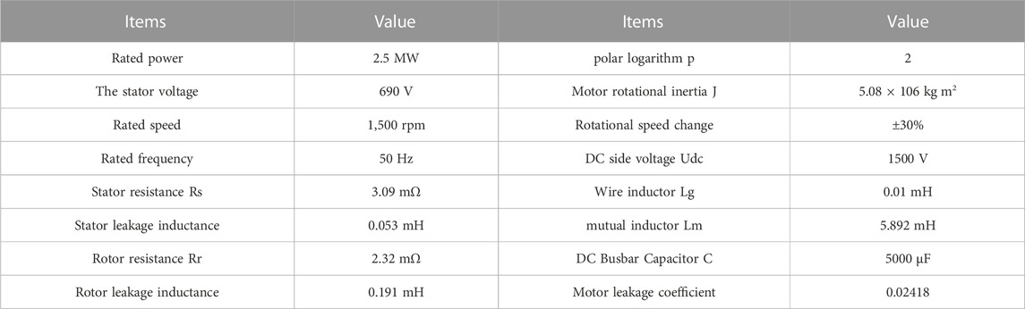
TABLE A2. Parameters of the doubly-fed induction generator model in the simulation.
Figure 10 shows different wind speed curves given by the wind turbine, which are divided into low wind speed, medium wind speed and high wind speed. Figure 11 shows the frequency variation curves of the power grid system under the condition of sudden load with different control strategies. In ①, the wind power system does not have the capacity of inertia response; In ②, the control strategy that the wind storage frequency modulation system can coordinate the inertia response and has no recovery link in the process of inertia response; In ③, the super capacitor in the wind storage system provides the inertia response power independently and has no recovery link in the inertia response process; In ④, the control strategy of multi-energy coordination of inertia response and recovery link in the process of inertia response in the combined frequency modulation system of wind storage; In ⑤, the super capacitors in the wind storage system independently provide the inertia response power and there is a recovery link in the inertia response process; In ⑥, the control strategy of the wind turbine provides the inertia response by releasing the kinetic energy of the rotor.
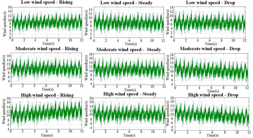
FIGURE 10. Different wind speed curves given for SCESS-DFIGs.
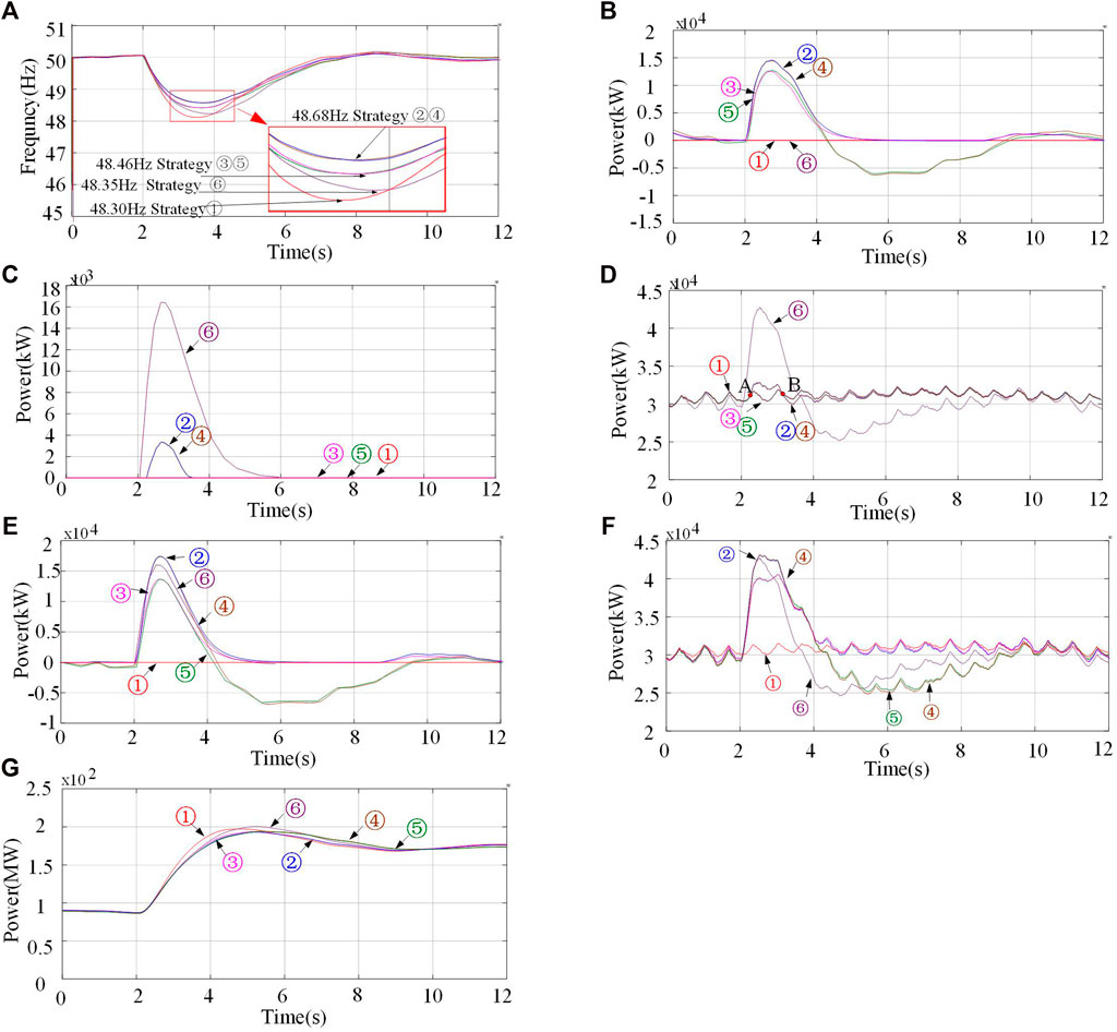
FIGURE 11. The simulation results.
It can be seen from Figure 11 that if the DFIG does not have inertia response, the power grid frequency drop depth reaches 48.30 Hz at most. When only the rotor kinetic energy release of the DFIG is used to provide the inertia response power, the grid frequency drop reaches 48.35 Hz. As can be seen from the figure, the lowest point of the system drop has a certain delay, which is mainly due to the release of rotor kinetic energy, which causes the wind turbine to fall out of the MPPT curve, and the capture of mechanical power leads to the loss of power generation. When the super capacitor is used to independently perform the frequency regulation, the deepest drop of the grid frequency reaches 48.46 Hz. As shown in Figure 11, the simulation results show that when the DFIG and the super capacitor are combined in frequency regulation, the deepest drop of the power grid frequency reaches 48.68 Hz. The power grid frequency of control strategy ③⑤ is affected by the converter capacity and real-time SOC, and its frequency modulation capability is weaker than that of control strategy ②④. Because the control strategy②④adopts the frequency regulation strategy based on super capacitor and supplemented by the release of rotor kinetic energy, the effect of mechanical energy capture is much smaller than that of the control strategy ⑥, which will not affect the normal operation of the wind generator.
Figure 11 shows the total output power of the super capacitor under different control strategies. Since the wind turbine releases part of the rotor kinetic energy, the converter has more power margin, and the output power of the super capacitor is higher than that of the control strategy ③⑤. Figure 11 shows the total output power based on the release of rotor kinetic energy under different control strategies. The control strategy ⑥ releases a large amount of rotor kinetic energy at the initial stage of inertia response. Control strategy ②④ releases a small amount of rotor kinetic energy to supplement the inertia response of the system. Figure 11 shows the total electric power curves of the inertia response process under different control strategies. This part of power is generated by the electromechanical energy conversion of the wind turbine, and does not include the regulating energy of the super capacitor. Due to the instantaneous absorption of a large amount of rotor kinetic energy, the wind turbine can increase the output power at the initial stage of inertia response to meet the demand of frequency modulation. However, with the release of rotor kinetic energy, the speed of the wind turbine slows down, resulting in a sudden drop in the output power of the wind turbine captured wind energy out of the MPPT curve. The control strategy ②④adopt the method of frequency modulation coordinated by super capacitor compensation and rotor kinetic energy, so in the inertia response stage (starting from point A), the wind turbine releases part of the kinetic energy, and the total power output of the wind turbine is greater than that of the control strategy ③⑤. When the rotor kinetic energy is released, the output power of the fan of the control strategy ②④ is lower than that of the control strategy ③⑤ for a short time at point B. However, in the overall inertia response process, the output energy of the control strategy ②④ is higher than that of the control strategy ③⑤, and the output power of the control strategy can provide more frequency modulation power in the frequency decreasing stage. Figure 11 shows the comparison of inertia response power curves based on different frequency regulation control strategies. The output power of control strategy ②④ in the process of inertia response is the largest among the six control strategies, and its inertia response regulation ability is the strongest. Compared with the control strategy ②, the super capacitor will absorb the power when the frequency change rate of the power grid increases. This has an adverse effect on the frequency recovery of the system. Figure 11 shows the total output power curves of the wind storage system under different control strategies. Compared with the other five control strategies, the control strategy ② can provide the maximum inertia corresponding power without affecting the recovery of the system. Figure 11 shows the comparison of output power curves of thermal power plants based on different frequency modulation control strategies. Figure 12 shows rotor speed, DFIG output power, wind storage system output power, super capacitor SOC, super capacitor output power, and kinetic energy release power of a single rotor of SCESS-DFIG for No.1, No.3, No.9, No.18, and No.27.
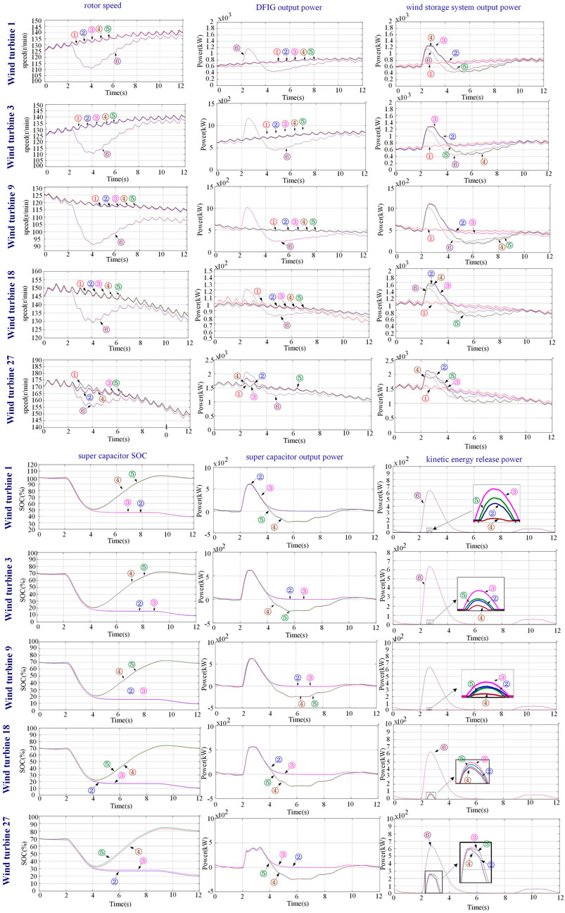
FIGURE 12. State operation curves of some SCESS-DFIGs under different working conditions.
6 Conclusion
This paper focuses on the problem that the DFIG has weak frequency regulation ability and is susceptible to “source” disturbance. Based on the inertia time constants of conventional synchronous generators, the inertia time constants and the actual inertia constants of the dual-fed wind power generation system under variable wind speed are defined.
The specific conclusions are as follows:
1. By analyzing and comparing the cost of different wind storage combined frequency regulation topologies and related parts, it is determined that the wind storage power generation architecture adopting distributed energy storage has higher economy.
2. According to the damping effect of different wind speed changes on the grid frequency changes during the frequency regulation process, the influence of instantaneous power changes on the inertia response of the generator set is divided into “negative inertia”, “positive inertia” and “excess inertia”.
3. By comparing the capacity of providing inertia response power and energy with different energy sources, it is determined that a single energy source cannot meet the inertia response demand of wind power system. The feasibility of multi-energy coordinated control to improve the inertia response capacity of SCESS-DFIG is demonstrated.
4. Considering the influence of wind speed variation and the protection of speed, an expanded state observer is established to estimate the variation of captured mechanical power caused by wind speed variation, and the results are applied to the design of frequency regulation control strategy.
5. Using the state of the generator rotor, the SOC of the super capacitor, and the estimation of the change of the captured mechanical power as the optimization conditions, a control strategy for the SCESS-DFIG to participate in the frequency regulation of the power grid is designed. The feasibility and advantages of the proposed frequency regulation control strategy are proved by constructing a 3 × 3 × 3 wind farm model, which includes the initial wind speed, the state of charge and the wind speed variation trend.
Data availability statement
The original contributions presented in the study are included in the article/Supplementary Material, further inquiries can be directed to the corresponding author.
Author contributions
DS was mainly responsible for the writing of this paper, completed the establishment of the mathematical model, and designed a multi-ability cooperative control strategy. FZ was mainly responsible for the establishment of the mathematical model under the condition of considering the actual engineering application, and completed the construction of some simulation models. YG is mainly responsible for the economic analysis of wind power and energy storage combined with different structures. Participated in the proofreading of articles. FM is mainly responsible for the collection, verification and analysis of simulation data. And participated in part of the simulation construction. WZ is responsible for consulting and analyzing the current situation at home and abroad, and collecting relevant national standards. Participated in the design of control strategies. JY is mainly responsible for basic principle analysis, paper typesetting, picture editing, proofreading and other work.
Conflict of interest
The authors declare that the research was conducted in the absence of any commercial or financial relationships that could be construed as a potential conflict of interest.
Publisher’s note
All claims expressed in this article are solely those of the authors and do not necessarily represent those of their affiliated organizations, or those of the publisher, the editors and the reviewers. Any product that may be evaluated in this article, or claim that may be made by its manufacturer, is not guaranteed or endorsed by the publisher.
References
Altin, M., Hansen, A. D., Barlas, T. K., Das, K., and Sakamuri, J. N. (2018). Optimization of short-term overproduction response of variable speed wind turbines. IEEE Trans. Sustain. Energy 9 (4), 1732–1739. doi:10.1109/tste.2018.2810898
Anping, H., Bo, Y., and Pengpeng, P. (2018). Study on inertial characteristics of energy storage system with power electronic interface. Proc. CSEE 38 (17), 4999–5008. [J].
Choi, J. W., Heo, S. Y., and Kim, M. K. (2016). Hybrid operation strategy of wind energy storage system for power grid frequency regulation. IET Generation, Transm. Distribution 10 (3), 736–749. doi:10.1049/iet-gtd.2015.0149
Chu, Z., Markovic, U., Hug, G., and Teng, F. (2020). Towards optimal system scheduling with synthetic inertia provision from wind turbines. IEEE Trans. Power Syst. 35 (5), 4056–4066. doi:10.1109/tpwrs.2020.2985843
GB/T 19963—2011 (2011). Technical rule for connecting wind farm to power system. Taiwan, China: National standards of people's republic of china.
Kang, M., Kim, K., Muljadi, E., Park, J. W., and Kang, Y. C. (2016). Frequency control support of a doubly-fed induction generator based on the torque limit. IEEE Trans. Power Syst. 31 (6), 4575–4583. doi:10.1109/tpwrs.2015.2514240
Li, B., Yang, S., Yang, B., and Fang, K. (2022). Robust nonlinear control of DFIG-based wind farms for damping inter-area oscillations of power systems. Front. Energy Res. 10, 878. doi:10.3389/fenrg.2022.936580
Li, H., Liu, D., and Zhao, D. (2021). Analysis and reflection on the development of power system towards the goal of carbon emission peak and carbon neutrality. Proc. CSEE 41 (18), 6245–6259.
Li, S., Wang, W., Zhang, X., and Li, C. (2021). Fuzzy adaptive virtual inertia control strategy of wind turbines based on system frequency response interval division. Power Syst. Technol. 45, 1658–1664.
Liang, K., Peng, X. T., Qin, S. Y., Wang, J. R., and Zhang, Z. (2020). Balloon atrial septostomy and transition of subcutaneous to intravenous prostacyclin infusion for rescuing advanced right heart failure in idiopathic pulmonary arterial hypertension: A case report. Proc. CSEE 4, 1–5. doi:10.1093/ehjcr/ytaa052
Liu, J., Yao, W., Wen, J., Ai, X., Luo, W., and Huang, Y. (2015). A wind farm virtual inertia compensation strategy based on energy storage system. Proc. CSEE 35 (7), 1596–1605.
Liu, K., Qu, Y., Kim, H. M., and Song, H. (2017). Avoiding frequency second dip in power unreserved control during wind power rotational speed recovery. IEEE Trans. power Syst. 33 (3), 3097–3106. doi:10.1109/tpwrs.2017.2761897
Liu, Z., Liu, F., Mei, S., Bi, D. Q., and Yao, Y. X. (2016). Application of extended state observer in wind turbines speed recovery after inertia response control. Proc. CSEE 36 (5), 1207–1217.
Miao, L., Wen, J., Xie, H., Yue, C., and Lee, W. J. (2015). Coordinated control strategy of wind turbine generator and energy storage equipment for frequency support. IEEE Trans. Industry Appl. 51 (4), 2732–2742. doi:10.1109/tia.2015.2394435
Musarrat, M. N., Islam, M. R., Muttaqi, K. M., and Sutanto, D. (2018). Enhanced frequency support from a PMSG-based wind energy conversion system integrated with a high temperature SMES in standalone power supply systems. IEEE Trans. Appl. Supercond. 29 (2), 1–6. doi:10.1109/tasc.2018.2882429
Ochoa, D., and Martinez, S. (2016). Fast-frequency response provided by DFIG-wind turbines and its impact on the grid. IEEE Trans. Power Syst. 32 (5), 4002–4011. doi:10.1109/tpwrs.2016.2636374
Peng, X., Yao, W., Yan, C., Wen, J., and Cheng, S. (2019). Two-stage variable proportion coefficient based frequency support of grid-connected DFIG-WTs. IEEE Trans. Power Syst. 35 (2), 962–974. doi:10.1109/tpwrs.2019.2943520
Si, X., Wu, X., You, F., Yuan, H., Xu, Y., and Yang, D. (2022). Primary frequency stability support of a DFIG in association with pitch angle control. Front. Energy Res. 9, 886. doi:10.3389/fenrg.2021.798037
Sun, C., Chen, J., and Tang, Z. (2021). “New energy wind power development status and future trends,” in Proceedings of the 2021 International Conference on Advanced Electrical Equipment and Reliable Operation (AEERO) Beijing, China, October 2021 (IEEE), 1–5.
Sun, D., Sun, L., Wu, F., Zhang, L., Geng, W., Peng, J., et al. (2019). Research on frequency inertia response control strategy of SCESS-DFIG system considering variable wind speed. J. Eng. 2019 (16), 2995–3001. doi:10.1049/joe.2018.8504
Tan, Y., Meegahapola, L., and Muttaqi, K. M. (2015). A suboptimal power-point-tracking-based primary frequency response strategy for DFIGs in hybrid remote area power supply systems. IEEE Trans. Energy Convers. 31 (1), 93–105. doi:10.1109/tec.2015.2476827
Xie, X., He, J., Mao, H., and Li, H. (2021). New issues and classification of power system stability with high shares of renewables and power electronics. Proc. CSEE 41 (2), 461–475.
Xin, B., Shan, B., and Li, Q. Rethinking of the “three elements of energy” toward carbon peak and carbon neutrality. Proc. CSEE 42 (9), 3117–3126.
Xu, Y., and Wang, H. (2021). Torque limit-based inertial control of a DFIG for rapid frequency stabilization. Front. Energy Res. 9, 728. doi:10.3389/fenrg.2021.788989
Yan, X., Cui, S., and Sun, Y. (2020). Inertia and primary frequency regulation strategy of doubly fed wind turbine based on super capacitor energy storage control. Power Syst. autom. 44 (14), 111–120. [J].
Yoo, Y., Jung, S., and Jang, G. (2019). Dynamic inertia response support by energy storage system with renewable energy integration substation. J. Mod. Power Syst. Clean Energy 8 (2), 260–266. doi:10.35833/mpce.2018.000760
Yuan, X., Cheng, S., and Hu, J. (2016). Multi-time scale voltage and power angle dynamics in power electronics dominated large power systems. Proc. Csee 36 (19), 5145–5154.
Zhao, Z. L., and Guo, B. Z. (2017). A novel extended state observer for output tracking of MIMO systems with mismatched uncertainty. IEEE Trans. Automatic Control 63 (1), 211–218. doi:10.1109/tac.2017.2720419
Appendix
Keywords: doubly fed induction generator, super capacitor, multi energy coordination control, source side random change, grid frequency modulation
Citation: Sun D, Zhao F, Guo Y, Meng F, Zheng W and Yu J (2023) Research on multi-energy cooperative participation of grid frequency inertia response control strategy for energy storage type doubly-fed wind turbine considering wind speed disturbance. Front. Energy Res. 11:1068080. doi: 10.3389/fenrg.2023.1068080
Received: 12 October 2022; Accepted: 09 January 2023;
Published: 23 January 2023.
Edited by:
Chenghong Gu, University of Bath, United KingdomReviewed by:
Evgeny Solomin, South Ural State University, RussiaZhuoli Zhao, Guangdong University of Technology, China
Copyright © 2023 Sun, Zhao, Guo, Meng, Zheng and Yu. This is an open-access article distributed under the terms of the Creative Commons Attribution License (CC BY). The use, distribution or reproduction in other forums is permitted, provided the original author(s) and the copyright owner(s) are credited and that the original publication in this journal is cited, in accordance with accepted academic practice. No use, distribution or reproduction is permitted which does not comply with these terms.
*Correspondence: Dongyang Sun, ggdaxx@163.com