Synchronous Generator Imitation Control and Dynamic Power Sharing for Distributed Power Generation Systems
 Huangqing Xiao
 Bicheng Liu
 - School of Electric Power Engineering, South China University of Technology, Guangzhou, China
In this paper, a control method called synchronous generator imitation control (SGIC) as well as a dynamic power sharing for distributed power generation systems (DPGSs) are presented. In order to imitate the behavior of a synchronous generator (SG), the SGIC method for the voltage source converter (VSC) station is proposed. The SGIC includes three loops, namely active power and frequency loop (Pf loop), reactive power and voltage loop (QU loop) as well as inner current loop. The Pf loop is used to emulate the swing equation of the SG. The exciter of the SG is mimicked by the QU loop. The inner current loop is developed for fast current and voltage regulations as well as current limiting. The system stability performances are analyzed through small-signal model, and the effectiveness of the proposed control is validated by PSCAD/EMTDC simulations. The results show that the Pf loop of the VSC emulates the motion equation of the SG rotor very well, which makes the VSC station to have inertia just as a SG; the VSC station can maintain a stable output voltage and regulate the reactive power at the same time; through the dynamic power sharing, precise power control, frequency offset elimination and system stability improvement are achieved; the system has the merits of fault ride-through capability as well as good dynamic performance.
Introduction
Recently, distributed power generation system (DPGS) with renewable energy sources, such as wind turbines and photovoltaic, has been attracting more and more attentions for solving energy crisis and environmental issues. However, when the penetration level of renewable energy is high, the grid equivalent rotational inertia becomes low (Blaabjerg et al., 2017). DPGS with low inertia, which is also known as weak grid, may result in poor voltage and frequency response during large disturbances (Xiao et al., 2021a).
In general, there are two ways to solve this problem. One is to install large number of storage batteries in the DPGS, which is not practical considering the high construction cost. The other solution is to develop new control method that can increase the grid inertia or make the interfacing voltage source converter (VSC) participate in voltage and frequency regulation of the grid (Ashabani and Mohamed, 2014a). This paper will look for a solution from the latter.
In conventional VSC control system, the dq-axis decoupling method is used. That is, the active power is controlled by regulating the d-axis current component, while the reactive power is controlled by regulating the q-axis current component. In this way, the active power and reactive power can be controlled independently. The exiting studies found that the widely used current vector controller for VSC based high voltage direct current (HVDC) systems is not applicable when the AC system is very weak (Zhang et al., 2011a; Zhou and Gole, 2012; Hu et al., 2019). When the AC system is weak (the short circuit ratio is small), the d-axis and q-axis of the current is no longer decoupled. The active power and reactive power cannot be regulated independently. Therefore, in weak AC system, the dq-axis decoupling characteristic of the current vector controller is destroyed, which may lead to the instability of the system (Zhang et al., 2011b).
In order to overcome the above limitation, the conventional droop control (CDC) method is usually adopted for the VSC station (Chandorkar et al., 1993; Coelho et al., 1999; Xiao et al., 2022). With the CDC method, the frequency and the amplitude of the output voltage are directly proportional to the real-time transmission active and reactive power. But there are some serious drawbacks for this method. Important among them are permanent offset of frequency due to the change of power, inaccurate power sharing and no contribution for the system inertia (Mohamed and El-Saadany, 2008), (Ashabani et al., 2015).
Another control method for the VSC connected to weak grid or islanded system is the virtual synchronous generator (VSG) control, which operates the VSC in the similar way as the synchronous generator (SG) (Beck and Hesse, 20072007). So far there have been many VSG models (Zhang et al., 2010; Zhong and Weiss, 2011; Zhong et al., 2014; Ashabani and Mohamed, 2014b; Guan et al., 2015). One of them is presented in (Zhong and Weiss, 2011), with which the characteristics of SG are well mimicked. But the additional control loop makes the control scheme complicated, and also this model is lack of current limiting capability. Another VSG model which is well known as power-synchronization control is proposed in (Zhang et al., 2010). This model is successfully used in powering a weak grid and achieves good performance. But the secondary frequency regulation is not realized by this model, which will cause the frequency offset. A simple and practical VSG model is realized in (Guan et al., 2015). The secondary frequency regulation is also achieved. But the exciter of the SG is not emulated, which means the reactive power cannot be controlled precisely.
In order to precisely control the power and optimize power sharing among distributed generators (DGs), higher level controllers (secondary or tertiary controllers) are usually activated. In general, the controller can be divided into two categories: centralized and decentralized (Xin et al., 2015; Olivares et al., 2014; Xiao et al., 2021b). In a decentralized system each DG is controlled by its local controller and the new DGs can be easily plugged into the grid (Xin et al., 2013). However, it is difficult for the decentralized controller to handle the operation of DPGS requiring high levels of coordination (Olivares et al., 2014). Therefore, centralized controllers containing communication system are needed in a DPGS with strong coupling between DGs. A power sharing method with communication is presented in (Liang et al., 2013) to precisely control the reactive power. But the frequency offset is not eliminated and also the system stability is very sensitive to the communication delays (Kahrobaeian and Ibrahim Mohamed, 2015).
Motivated by the aforementioned reasons, an enhanced control and a novel power sharing for DPGS are proposed in this paper. In this control scheme, each DG adopts a novel control method called synchronous generator imitation control (SGIC). The novel SGIC consists of three loops, including active power and frequency loop (Pf loop), reactive power and voltage loop (QU loop) as well as inner current loop. The novelty and contribution of this paper is summarized as follows:
1) An enhanced control method called synchronous generator imitation control is proposed in this paper. With the proposed control, the VSC could imitate the behavior of a synchronous generator so that the multiple VSCs could operate stably in the weak AC grid or islanded system as well as provide frequency and voltage support for the power systems.
2) A dynamic power sharing control for the DPGS is also proposed. With this power sharing, the reference values of the active and reactive power are adjusted dynamically instead of being constant. As a result, the power can be allocated precisely; the frequency offset can be eliminated; and the system stability can be improved.
This paper is organized as follows. Synchronous Generator Imitation Control of VSC Section presents the principle of SGIC method. The dynamic power sharing for DGPS is introduced in Dynamic Power Sharing for DPGS Section. The small-signal model of a DGPS with multiple DGs is built and the stability performance is analysis in Small-Signal Analysis for a DPGS With the Proposed Control Scheme Section. Case Study Section shows the simulation results of the system in different operation conditions. Finally, Conclusion Section concludes the paper.
Synchronous Generator Imitation Control of VSC
Due to the high penetration level of renewable energy in the power system, the equivalent rotational inertia of the grid is dramatically reduced. It will be of great benefit if the VSC stations can increase the inertia of the grid just like a SG. In such a manner, the VSC stations can also provide frequency and voltage support for the local grid. In this section, the SGIC method, including inner current loop, Pf loop and QU loop, is presented.
Inner Current Loop
The equivalent circuit of VSC connected to an AC system is shown in Figure 1 According to the VSC mathematical model in (Xu et al., 2005; Honglin Zhou et al., 2011; Xiao et al., 2015), the equations describing the dynamic characteristics of the VSC can be rewritten as
where, usj (j = a,b,c) denotes the grid voltage of phase j. uvj and ivj represent the output voltage and current of the VSC respectively. R and L are the resistance and inductance of the interfacing reactor (Xiao et al., 2015). From Eq. 1 it can be seen that the output current of the VSC ivj can be controlled by adjusting the output voltage uvj. In the dq-axis synchronous frame, the dynamic equations of the VSC can be expressed as (Xiao et al., 2015)
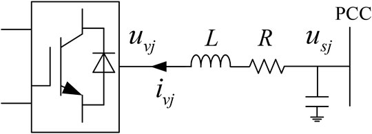
FIGURE 1. Single-phase equivalent circuit of VSC connected to AC system.
where, ω is the angular frequency of the power grid. According to Eq. 2 the inner current loop is built in Figure 2. It should be noted that the inner current loop can provide current regulation and limit the current amplitude during fault and transient process.
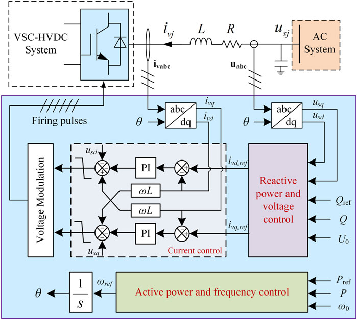
FIGURE 2. Overall control diagram of the proposed SGIC method.
Active Power and Frequency Loop
The inertia effect of the SG is mainly reflected in the motion of the rotor. When there is an unbalance between mechanical and electromagnetic power or torque, the net power or torque will change the angular velocity of the rotor. The inertia of the SG directly affects the angular acceleration. The motion equation representing this process is widely known as the swing equation (Kundru, 1993)
where, P0 is the mechanical power for the SG or the reference active power for the VSC in this paper. P is the electromagnetic power for the SG or the output transmission power for the VSC. J is the inertia coefficient and D is the damping factor. ω0 is the nominal angular frequency of the power grid.
Applying the Laplace transform to Eq. 3, the expression in Eq. 4 can be obtained. Then the reference of angular frequency is given by Equation 5. Equation 5 is the control equation of the Pf loop for the SGIC.
If the inertia coefficient J = 0, Equation 5 can be transformed to the conventional active power droop control equation
From Eqs 5, 6 it can be seen that the Pf loop can be realized by adding a first-order inertia element to the CDC method. This not only increases the inertia of the local grid, but also greatly simplifies the design process of the controller. Furthermore, the virtual inertia coefficient J is a parameter of the controller. Its value can be adjusted to an expected one according to the operation conditions of the grid. In this way, the VSC can achieve the performances that the SG cannot realize because the inertia coefficient of a SG is fixed.
Reactive Power and Voltage Loop (QU loop)
The QU loop is used to emulate the exciter of the SG. The main function of the exciter comprises the control of voltage and reactive power flow, as well as the enhancement of system stability (Kundru, 1993).
The QU loop contains two parts, including the reactive power regulation component and the output voltage regulation component. Therefore, the reference voltage U* also consists of two parts. One part is the no-load voltage U0, the other is the fluctuation component ∆U which is used to regulate the reactive power. Thus, the control equation of QU loop can be expressed as
where, Q0 is the reference reactive power, and Q is the output reactive power of the VSC.
When the integral constant kT = 0, Eq. 7 is transformed to the conventional reactive power droop control equation
After the reference of voltage is obtained, the output current reference i∗vd and i∗vq of the inner current loop can be get through PI controllers
where the references of dq-axis voltage components are given by
So far, the complete model of the SGIC for a VSC station is obtained. The overall control diagram can be seen in Figure 2.
Dynamic Power Sharing for DPGS
When the CDC method or the proposed SGIC method is used in a DPGS, there exist three problems for the whole system. 1) The output power of the VSC stations will deviate from its original set value due to the change of the load demand, which in turn causes the frequency offsets. 2) The reactive power cannot be shared accurately among VSC stations. 3) System stability is highly sensitive to the droop coefficients and the communication delays, which results in low stability margin.
In this section, a novel method named dynamic power sharing is proposed to solve the above three problems.
When the SGIC method is used, each VSC station can be regarded as a SG. In this paper, the real SG and the VSC stations with SGIC method are collectively called generation units (GUs).
In order to eliminate the frequency offset, the power references are adjusted dynamically. The references of active power and reactive power are given by
where, P GUi is the active power reference of GUi and Q GUi is the reactive power reference. Ptotal = ∑P GUi and Qtotal = ∑Q GUi are the total active and reactive powers of the local grid. λi is the active power allocation factor of GUi. γi is the reactive power allocation factor of GUi. The active and reactive power allocation factors satisfy the following equations
Figure 3 is the schematic diagram of the dynamic power sharing. The active and reactive powers generated by each GU are transmitted to the energy management system (EMS) so that the total power demand can be calculated. Then the desired active and reactive powers λiPtotal, γiQtotal are sent back to the GUs as their references.
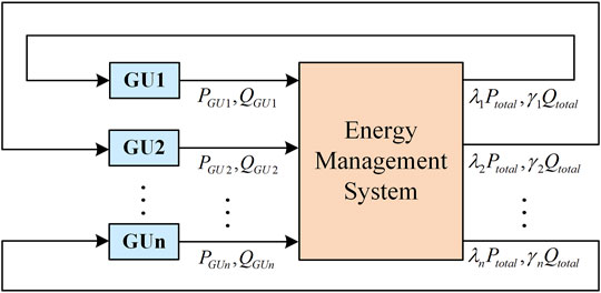
FIGURE 3. Schematic diagram of the dynamic power sharing.
Because the power references are dynamically adjusted according to the real-time power demand, the frequency offset can be eliminated.
Inserting Eqs 13, 14 to Eqs 5, 7, the following equations can be obtained
One of the issues that need to be considered in a centralized based EMS is the handling for a failure of the communication system. When the communication system fails, the power reference for each GU becomes zero (that is λi = γi = 0). In order to stabilize the voltage, the integral term of the QU loop should be set to zero (that is kTi = 0). In this way, the control equations can be rewritten as in Eqs 19, 20
Small-Signal Analysis for a DPGS With the Proposed Control Scheme
In order to analyze the dynamic performance of the system and optimize the controller parameters, it is necessary to carry out small-signal modeling and analysis on the system with the proposed control scheme. This section will perform a small-signal analysis of a DPGS containing n distributed power supplies.
The load angle derivative is given by
Linearization of Eq. 17 yields
The average active and reactive powers are obtained through low-pass filter as following equations
where ωc is the bandwidth of the low-pass filter. pi and qi are the instantaneous active and reactive power. The small-signal equations of Eqs 23, 24 are given by
The linearized form of Eq. 18 can be expressed as
For a DPGS with n power-generating nodes and m load nodes, the network equations can be written as
In order to simplify the analysis, Kron reduction (Anderson and Foad, 2003)- (Dorfler and Bullo, 2013) is used on Eq. 28. Then we can get the system equation containing only n power-generating nodes as
The active and reactive power injected by each generation unit can be expressed as
where Gij and Bij are the real and imaginary parts of the element Yij in the equivalent admittance matrix Yeq (ie, Yij = Gij + jBij).
The linearized form of Eqs 30, 31 can be presented as
The small-signal model of a DPGS with n distributed power supplies is described in Eqs 21, 22; Eqs 25–27; Eqs 30–33. The overall system small-signal state-space model can be derived as
where state variable set is
The proposed model is applied to a DPGS shown in Figure 4. In this system, two VSC stations supply power to a common load through respective connected lines. In order to simplify the analysis, it is assumed that the parameters of the two VSC stations are the same. The active power allocation factor and reactive power allocation factor for the two VSC are 0.5.
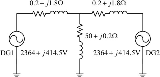
FIGURE 4. A DPGS for small-signal analysis.
Figure 5 shows the system eigenvalue spectrum with different control parameters.
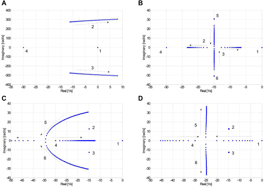
FIGURE 5. System eigenvalue spectrum when (A) kG = 0, kT = 0, D = 1,000 and J changes from 0.1 to 0.5; (B) kG = 0, kT = 0.03, J = 0.1, D from 1e5 to 5e5; (C) kT = 0.03, D = 2e5, J = 0.1 and kG changes from 2e-5 to 2e-3; (D) kG = 5e-4, D = 2e5, J = 0.1 and kT changes from 0.005 to 0.05.
Figure 5A shows the system root locus when kG = 0, kT = 0, D = 1,000 and J changes from 0.1 to 0.5. It can be seen from the figure that with the increase of J, eigen2 and eigen3 move from the left half plane to the imaginary axis. In particular, when J > 0.35, the two conjugate complex roots go into the right half plane, indicating that the system is unstable.
Figure 5B shows the location of eigenvalue with kG = 0, kT = 0.03, J = 0.1, D from 1e5 to 5e5. As can be seen from the figure, eigen2 and eigen3 are very sensitive to parameter D while eigen5 and eigen6 are almost constant. As D increases, eigen2 and eigen3 change from a pair of conjugate complex roots to two real roots. The absolute value of a real root becomes smaller gradually, which indicates that the stability margin of the system decreases.
Figure 5C shows the system eigenvalue spectrum when kT = 0.03, D = 2e5, J = 0.1 and kG changes from 2e-5 to 2e-3. It can be seen that eigen5 and eigen6 are greatly influenced by kG. When kG is less than 1e-3, with the increase of kG, the speed of the system response to the disturbance is accelerated.
Figure 5D shows the system root locus when kG = 5e-4, D = 2e5, J = 0.1 and kT changes from 0.005 to 0.05. When kT < 0.015, eigen5 and eigen6 are negative real roots; when kT > 0.015, a pair of conjugate complex roots is generated and the oscillation frequency of the system increases. But other dominant roots are almost constant, which means satisfactory performance and fast response can be achieved without the loss of stability.
Case Study
In order to verify the accuracy and validity of the proposed control strategy, a DPGS with three distributed generators shown in Figure 6 is built in PSCAD/EMTDC simulation software. The control parameters of the VSC stations can be seen in Table 1.
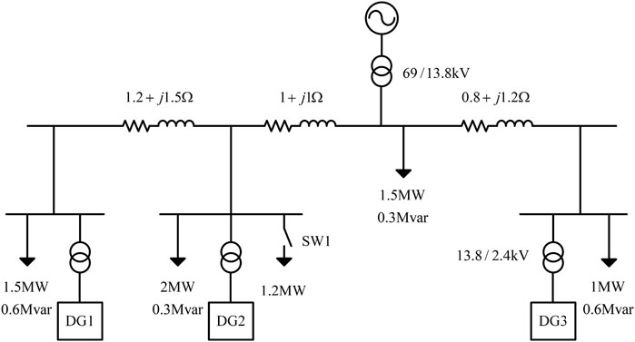
FIGURE 6. A DPGS with three distributed generators.
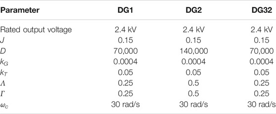
TABLE 1. Control parameters of three VSC stations.
Case 1: Load Change
Assuming that the system operates at steady state before t = 0. At t = 2s, an additional load of 1.2 MW is added to the system by closing switch SW1. The corresponding responses of the system are shown in Figure 7. When the additional load is added, the system frequency drops due to the power unbalance. After that the SGIC takes effect and the three DGs inject more power to the system. Thus, the system frequency increases gradually. Finally, the system restored to a new steady state. During the transient process, the active power of DG2 is increased from 3.0 to 3.6 MW with increment of 0.6 MW. For DG1 and DG3, both active powers are increased from 1.5 to 1.8 MW with increment of 0.3 MW. The ratio of the power increments for the three DGs is 1:2:1, which is equal to the ratio of their allocation factors (0.25:0.5:0.25). It also can be seen that the system frequency restores its nominal value. That means the change of the active power does not lead to frequency offset, which is one of the advantages of the proposed control scheme.
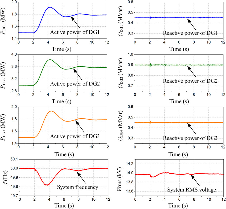
FIGURE 7. Simulation results under load change.
Case 2: Adjustment of Power Allocation Factors
Another advantage of the proposed control scheme is that the system can flexibly select the optimal power output according to different operating conditions. The system adjusts the active and reactive power outputs of DGs at t = 2s so that DG1 provides 40% of the total demands, while both DG2 and DG3 provide 30%. The system performances are illustrated in Figure 8. This process can be achieved only by adjusting the power allocation factors of each DG to λ1 = γ1 = 0.4, λ2 = γ2 = 0.3 and λ3 = γ3 = 0.3. However, for the CDC method, it is necessary to change the controllers’ droop coefficients of each DG to realize this function. As can be seen from the figure, after less than 1s the system transition to a new steady state point. During the transient, the system voltage and frequency fluctuations are very small, which indicates that the disturbance to the system is small.
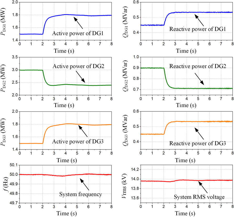
FIGURE 8. Simulation results with power allocation factors adjustment.
Case 3: Station Fault
A fault is applied in DG1, which makes it disconnected from the local grid at t = 2s. After fault, DG1 no longer participates in dynamic power sharing. The loss of the power is compensated by DG2 and DG3. Figure 9 shows the corresponding responses of the system. From the figure it can be seen that the active and reactive power of DG2 is changed from 3.0 MW, 0.9 Mvar to 4.0 MW, 1.2 Mvar; and DG3 from 1.5 MW, 0.45 Mvar to 2.0 MW, 0.6 Mvar. The system frequency decreases at the initial state due to the loss of DG1, but restores to its nominal value when DG2 and DG3 compensate the loss. The voltage is mainly affected by reactive power. So, when the reactive power is changed, the voltage will also change. Even though the total amount of reactive power restores to the pre-defined value, the voltage cannot restore to the original value because the voltage is a locally quantity and the its allocation will also change the voltage. This simulation case also shows that the outage of one VSC station will not cause the blackout of the local grid, which means that the system with the proposed control scheme has high reliability and stability.
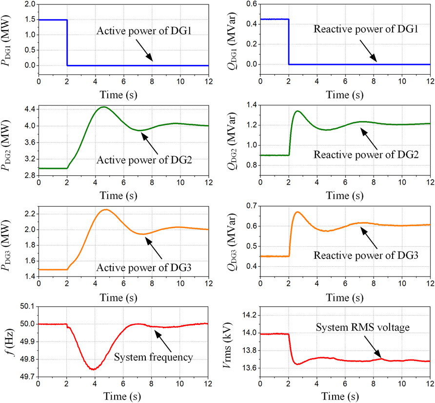
FIGURE 9. Simulation results under station fault condition.
Case 4: Performances with Communication Delays
Time delay is an unavoidable problem for communication systems. The time delay of a communication system with quantities measured on a remote bus can be more than 100 ms (Milano and Anghel, 2012). But it loses stability when the communication delay reaches 24 ms for some fully centralized EMSs (Kahrobaeian and Ibrahim Mohamed, 2015). This indicates that the communication delay is a key factor affecting the stability of the fully centralized communication system. As a contrast, the control scheme proposed in this paper only needs to transmit the power reference values without transmitting voltage amplitude and angle reference and other quantities. Therefore, the time delay does not affect the stability of the system. Figure 10 shows the system performance when the active power allocation factors change at t = 2s with 1s of communication delay. It can be seen that the new active power references take effect after 1s delay. The system has good steady state and dynamic performance.
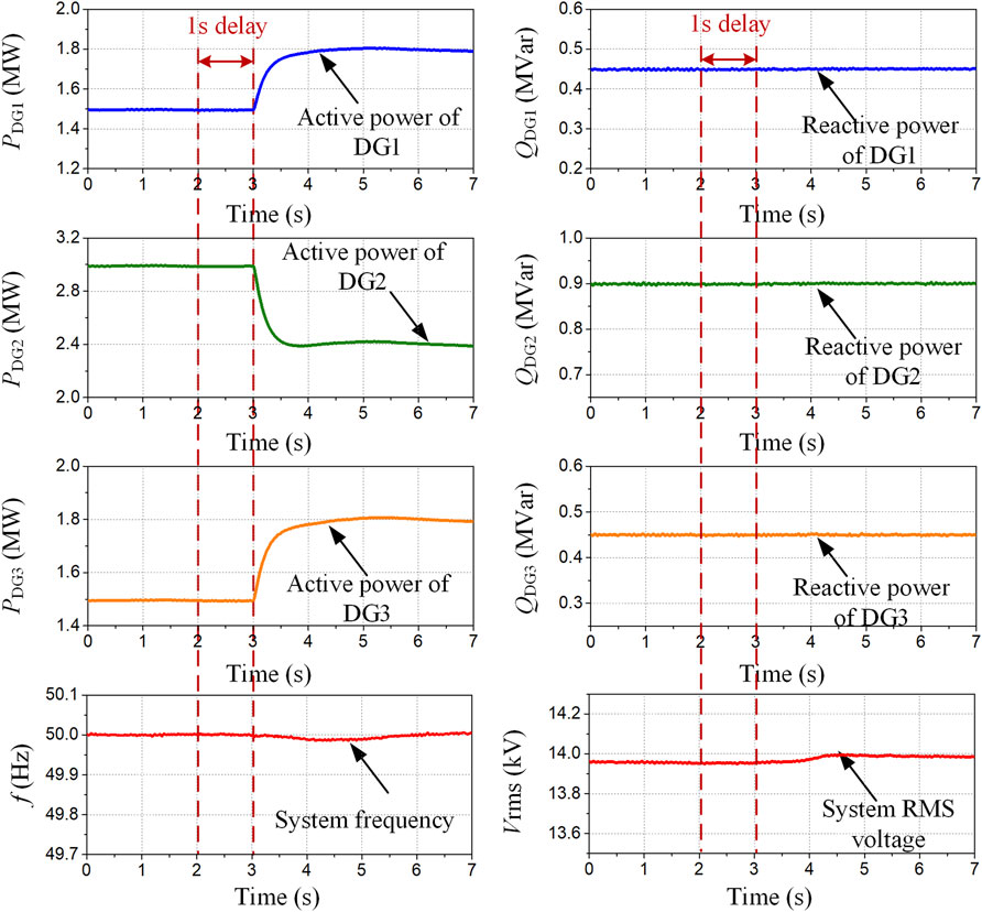
FIGURE 10. Simulation results with communication delay.
Conclusion
This paper presents a control and power sharing method for the distributed power generation system. In this scheme, each of the VSC stations adopts the proposed SGIC method. In order to eliminate the frequency offset, control the power precisely and improve the system stability when there are communication delays, a novel control called dynamic power sharing is proposed. Small-signal model of the whole system has been built and analyzed. A DPGS with three DGs is built in PSCAD/EMTDC software. Various operation conditions including load changes, power allocation factors adjustment, station fault and communication delay are simulated. According to this paper, the important advantages for the proposed scheme can be concluded as follows:
1) The Pf loop is designed through simply adding a first-order inertia element to the CDC method, by which the VSC has the similar inertia as the SG. The QU loop is used to imitate the exciter of the SG. With this loop the VSC station is able to keep the output voltage stable and control the reactive power at the same time.
2) The inner current loop merits fast current response and current limiting ability, which can avoid overcurrent problems during converter blocking or fault.
3) Through the dynamic power sharing, precise power control, frequency offset elimination and system stability improvement are achieved.
4) With the proposed scheme, the system has the merits of fault ride-through capability as well as good dynamic performance.
Data Availability Statement
The raw data supporting the conclusions of this article will be made available by the authors, without undue reservation.
Author Contributions
HX: Conceptualization, Methodology, Writing—original draft. BL and XH: Software, Data curation. ZC: Writing—review and editing.
Funding
This work was supported by the Science and Technology Project of China Southern Power Grid Corporation under Grant GDKJXM20198236.
Conflict of Interest
The authors declare that the research was conducted in the absence of any commercial or financial relationships that could be construed as a potential conflict of interest.
Publisher’s Note
All claims expressed in this article are solely those of the authors and do not necessarily represent those of their affiliated organizations, or those of the publisher, the editors and the reviewers. Any product that may be evaluated in this article, orclaim that may be made by its manufacturer, is not guaranteed or endorsed by the publisher.
References
Anderson, P., and Foad, A. (2003). Power System Control and Stability. Hoboken, NJ: Wiley-IEEE Press.
Ashabani, M., and Mohamed, Y. A.-R. I. (2014a). Integrating VSCs to Weak Grids by Nonlinear Power Damping Controller with Self-Synchronization Capability. IEEE Trans. Power Syst. 29 (2), 805–814. doi:10.1109/tpwrs.2013.2280659
Ashabani, M., Mohamed, Y. A.-R. I., Mirsalim, M., and Aghashabani, M. (2015). Multivariable Droop Control of Synchronous Current Converters in Weak Grids/Microgrids with Decoupled Dq-Axes Currents. IEEE Trans. Smart Grid 6 (4), 1610–1620. doi:10.1109/tsg.2015.2392373
Ashabani, M., and Mohamed, Y. A.-R. I. (2014b). Novel Comprehensive Control Framework for Incorporating VSCs to Smart Power Grids Using Bidirectional Synchronous-VSC. IEEE Trans. Power Syst. 29 (2), 943–957. doi:10.1109/tpwrs.2013.2287291
Beck, H. P., and Hesse, R. (20072007). Virtual Synchronous Machine. in 9th International Conference on Electrical Power Quality and Utilisation. Barcelona, 1–6. doi:10.1109/epqu.2007.4424220
Blaabjerg, F., Yang, Y., Yang, D., and Wang, X. (2017). Distributed Power-Generation Systems and Protection. Proc. IEEE 105 (7), 1311–1331. doi:10.1109/jproc.2017.2696878
Chandorkar, M. C., Divan, D. M., and Adapa, R. (1993). Control of Parallel Connected Inverters in Standalone AC Supply Systems. IEEE Trans. Ind. Applicat. 29 (1), 136–143. doi:10.1109/28.195899
Coelho, E. A. A., Cortizo, P. C., and Garcia, P. F. D. (1999). Small Signal Stability for Single Phase Inverter Connected to Stiff AC systemIndustry Applications Conference. Thirty-fourth IAS Annu. Meet. Conf. Rec. 1999 IEEE, Phoenix, AZ 4, 2180–2187. doi:10.1109/ias.1999.798756
Dorfler, F., and Bullo, F. (2013). Kron Reduction of Graphs with Applications to Electrical Networks. IEEE Trans. Circuits Syst. 60 (1), 150–163. doi:10.1109/tcsi.2012.2215780
Guan, M., Pan, W., Zhang, J., Hao, Q., Cheng, J., and Zheng, X. (2015). Synchronous Generator Emulation Control Strategy for Voltage Source Converter (VSC) Stations. IEEE Trans. Power Syst. 30 (6), 3093–3101. doi:10.1109/tpwrs.2014.2384498
Honglin Zhou, Z., Geng Yang, Y., and Jun Wang, W. (2011). Modeling, Analysis, and Control for the Rectifier of Hybrid HVdc Systems for DFIG-Based Wind Farms. IEEE Trans. Energ. Convers. 26 (1), 340–353. doi:10.1109/tec.2010.2096819
Hu, Q., Fu, L., Ma, F., and Ji, F. (2019). Large Signal Synchronizing Instability of PLL-Based VSC Connected to Weak AC Grid. IEEE Trans. Power Syst. 34 (4), 3220–3229. doi:10.1109/tpwrs.2019.2892224
Kahrobaeian, A., and Ibrahim Mohamed, Y. A.-R. (2015). Networked-Based Hybrid Distributed Power Sharing and Control for Islanded Microgrid Systems. IEEE Trans. Power Electron. 30 (2), 603–617. doi:10.1109/tpel.2014.2312425
Liang, H., Choi, B. J., Zhuang, W., and Shen, X. (2013). Stability Enhancement of Decentralized Inverter Control through Wireless Communications in Microgrids. IEEE Trans. Smart Grid 4 (1), 321–331. doi:10.1109/tsg.2012.2226064
Milano, F., and Anghel, M. (2012). Impact of Time Delays on Power System Stability. IEEE Trans. Circuits Syst. 59 (4), 889–900. doi:10.1109/tcsi.2011.2169744
Mohamed, Y., and El-Saadany, E. F. (2008). Adaptive Decentralized Droop Controller to Preserve Power Sharing Stability of Paralleled Inverters in Distributed Generation Microgrids. IEEE Trans. Power Electron. 23 (6), 2806–2816. doi:10.1109/tpel.2008.2005100
Olivares, D. E., Mehrizi-Sani, A., Etemadi, A. H., Canizares, C. A., Iravani, R., Kazerani, M., et al. (2014). Trends in Microgrid Control. IEEE Trans. Smart Grid 5 (4), 1905–1919. doi:10.1109/tsg.2013.2295514
Xiao, H., Huang, X., Xu, F., Dai, L., Zhang, Y., and Cai, Z. (2022). Improved Multiline HVDC Circuit Breakers with Asymmetric Conducting Branches. Int. J. Electr. Power Energ. Syst. 137, 107882. doi:10.1016/j.ijepes.2021.107882
Xiao, H., Sun, K., Pan, J., Li, Y., and Liu, Y. (2021b). Review of Hybrid HVDC Systems Combining Line Communicated Converter and Voltage Source Converter. Int. J. Electr. Power Energ. Syst. 129, 106713. doi:10.1016/j.ijepes.2020.106713
Xiao, H., Sun, K., Pan, J., Xiao, L., Gan, C., and Liu, Y. (2021a). Coordinated Frequency Regulation Among Asynchronous AC Grids with an MTDC System. Int. J. Electr. Power Energ. Syst. 126 (3), 1–11. doi:10.1016/j.ijepes.2020.106604
Xiao, H., Xu, Z., Xue, G. Y., and Tang, G. (2015). Complete Mathematical Model Derivation for Modular Multilevel Converter Based on Successive Approximation Approach. IET Power Elect. 8 (12), 2396–2410. doi:10.1049/iet-pel.2014.0892
Xin, H., Zhang, L., Wang, Z., Gan, D., and Wong, K. P. (2015). Control of Island AC Microgrids Using a Fully Distributed Approach. IEEE Trans. Smart Grid 6 (2), 943–945. doi:10.1109/tsg.2014.2378694
Xin, H., Zhang, M., Seuss, J., Wang, Z., and Gan, D. (2013). A Real-Time Power Allocation Algorithm and its Communication Optimization for Geographically Dispersed Energy Storage Systems. IEEE Trans. Power Syst. 28 (4), 4732–4741. doi:10.1109/tpwrs.2013.2277592
Xu, L., Andersen, B. R., and Cartwright, P. (2005). VSC Transmission Operating under Unbalanced AC Conditions-Analysis and Control Design. IEEE Trans. Power Deliv. 20, 427–434. doi:10.1109/tpwrd.2004.835032
Zhang, L., Harnefors, L., and Nee, H.-P. (2011a). Interconnection of Two Very Weak AC Systems by VSC-HVDC Links Using Power-Synchronization Control. IEEE Trans. Power Syst. 26 (1), 344–355. doi:10.1109/tpwrs.2010.2047875
Zhang, L., Harnefors, L., and Nee, H.-P. (2011b). Modeling and Control of VSC-HVDC Links Connected to Island Systems. IEEE Trans. Power Syst. 26 (2), 783–793. doi:10.1109/tpwrs.2010.2070085
Zhang, L., Harnefors, L., and Nee, H.-P. (2010). Power-Synchronization Control of Grid-Connected Voltage-Source Converters. IEEE Trans. Power Syst. 25 (2), 809–820. doi:10.1109/tpwrs.2009.2032231
Zhong, Q. C., Phi-Long Nguyen, P. L., Wanxing Sheng, Z., and Sheng, W. (2014). Self-Synchronized Synchronverters: Inverters without a Dedicated Synchronization Unit. IEEE Trans. Power Electron. 29 (2), 617–630. doi:10.1109/tpel.2013.2258684
Zhong, Q.-C., and Weiss, G. (2011). Synchronverters: Inverters that Mimic Synchronous Generators. IEEE Trans. Ind. Electron. 58 (4), 1259–1267. doi:10.1109/tie.2010.2048839
Keywords: distributed power generation system, inertia, small-signal model, dynamic power sharing, synchronous generator imitation control
Citation: Xiao H, Liu B, Huang X and Cai Z (2022) Synchronous Generator Imitation Control and Dynamic Power Sharing for Distributed Power Generation Systems. Front. Energy Res. 10:842318. doi: 10.3389/fenrg.2022.842318
Received: 23 December 2021; Accepted: 09 February 2022;
Published: 28 February 2022.
Edited by:
Chee Wei Tan, University of Technology Malaysia, MalaysiaReviewed by:
Razman Ayop, University of Technology Malaysia, MalaysiaJitendra Kumar, National Institute of Technology, Jamshedpur, India
Copyright © 2022 Xiao, Liu, Huang and Cai. This is an open-access article distributed under the terms of the Creative Commons Attribution License (CC BY). The use, distribution or reproduction in other forums is permitted, provided the original author(s) and the copyright owner(s) are credited and that the original publication in this journal is cited, in accordance with accepted academic practice. No use, distribution or reproduction is permitted which does not comply with these terms.
*Correspondence: Huangqing Xiao, xiaohq@scut.edu.cn