Power optimization control of VSC-HVDC system for electromechanical oscillation suppression and grid frequency control
 Chaohao Bi1
  Yang Qian
 Jianquan Shi
- 1Guangzhou Power Supply Bureau, Guangdong Power Grid Co., Ltd., Guangdong, China
- 2School of Automation, Nanjing Institute of Technology, Nanjing, China
The voltage source converter (VSC) based high-voltage DC (HVDC) transmission system usually adopts damping and inertia control to quickly and independently adjust the active- and reactive- power, to improve the frequency stability and suppress the electromechanical oscillations of the power grid. This paper first analyzes the effect of the proportional-derivative (PD) controller parameter on the HVDC output power. The study shows that when the proportional-derivative controller parameter is increased to the limit value, HVDC will operate in the rapid power compensation (RPC) mode. Namely, according to the positive or negative polarities of the rotor speed deviation and the grid frequency deviation, the active- and reactive- power limits are used as the reference to rapidly control the output power, thereby minimizing the system’s unbalanced power, the rotor oscillation, and the frequency fluctuation. To this end, this paper proposes a coordinated active-/reactive- power control strategy for the VSC-HVDC system based on the RPC mode to suppress the grid electromechanical and frequency oscillations. The RPC mode enables HVDC to quickly release/absorb power, to compensate for system’s required power shortage or suppress excess power. When the speed deviation, the frequency deviation, and their rates of change meet the requirements, the damping control is used to make HVDC exit the RPC mode and further enhance the ability of the VSC-HVDC system. Simulation results prove the effectiveness of the proposed power optimization control strategy.
1 Introduction
With the continuous advancement of the low-carbon energy strategy in China, there are continuously increasing applications of large-scale generation of new energies, Liu et al. (2020); You et al. (2022), and the installed proportion of synchronous generators (SGs) has gradually decreased. The rotating reserve and inertia have been significantly reduced, the frequency fluctuations and electromechanical oscillations of the power grid frequently occur, posing a great threat and challenge to the safe and stable operation of the power grid. As a result, maintaining grid frequency stability and effectively suppressing electromechanical oscillations are critical issues, Kundur et al. (2004). Power electronics connected to the public grid must actively participate in frequency control and oscillation suppression, Xu and Wang (2021).
Existing solutions mainly include: 1) The power system stabilizer to compensate for the negative damping, Kumar (2016); 2) The installation of synchronous condensers to improve the inertia level and damping ability of the power system to suppress electromechanical oscillations and frequency fluctuations, Nguyen et al. (2019); 3) The use of reactive power compensation devices such as the static synchronous compensator to regulate the reactive power output and change the voltage level and power flow distribution of the system, thereby suppressing the grid electromechanical oscillations, Li et al. (2020); 4) The use of energy storage devices to quickly emit or absorb active and reactive power to maintain the active power balance in the system and suppress power oscillations, yet energy storage devices are more expensive and difficult to apply on a large scale, Zhu et al. (2019); 5) The use of the power of the new energies such as photovoltaic and wind generations to compensate for the power deficits or surpluses in the power system Yang et al. (2021), but new energy generations typically operate in the maximum power point tracking mode; if used for grid frequency control and electromechanical oscillation suppression, a certain amount of capacity must be reserved for active participation in the regulation of the system dynamic process at any time, which will sacrifice their inherent power generation capacity, Li et al. (2020).
Currently, the voltage source converter (VSC) based high-voltage DC (HVDC) transmission system is one of the best solutions for large-scale renewable energy exploiting, and has been widely applied in practical projects such as grid-connected wind farms, weak grid power transmission, and islanding power supply, Zhang et al. (2011); Lee et al. (2018). As the VSC-HVDC system has the advantage of fast and independent control of active and reactive power, and it does not require reactive power compensation from the AC grid, it has attracted a lot of attention for suppressing electromechanical oscillations and maintaining power system frequency stability, Wang et al. (2019); Xiong et al. (2021b). Sun et al. (2021) states that when the VSC-HVDC system uses a constant power control strategy, the damping level of the power system cannot be increased. For this reason, the VSC-HVDC system should operate in the variable power control mode to inject real-time adjustable active or reactive power into the SG network based on the change of the grid state, in order to enhance the suppression of electromechanical and frequency oscillations by the VSC-HVDC system. In addition, Varma and Maleki (2019) points out that when the VSC absorbs or emits reactive power to change its voltage at the integration point and improve the grid power distribution, it functions as a STATCOM that can quickly and smoothly modulate the reactive power without the need for a large amount of reactive power provided by the grid Xiong et al. (2015).
To realize that HVDC actively participates in the frequency control and suppresses electromechanical oscillations, the VSC control needs to be improved, such as by adding droop control, inertia control, and proportional-derivative (PD) control, Peng et al. (2020); Shi et al. (2021). Droop control and inertia control cannot adjust the magnitude and speed of frequency change at the same time, Xiong et al. (2022); Wang et al. (2015); the PD control necessitates high precision on system parameters, and the expected control performance is difficult to achieve, Li et al. (2020); Ling et al. (2021). Accordingly, Fang et al. (2018) improved the original virtual inertia control, and proposed a virtual SG (VSG) control with characteristics similar to SGs. To suppress the inherent power oscillation problem of the VSG control and improve the frequency response speed, Kerdphol et al. (2019) proposed an improved VSG strategy based on the fuzzy logic algorithm. However, various improved VSG strategies require information on grid inertia and damping parameters to obtain the optimal inertia and damping control parameters, Ali et al. (2019). To this end, Xiong et al. (2021a) developed a frequency trajectory planning control that decouples from the grid’s disturbances and inertia/damping information that cannot be obtained.
All the previously discussed schemes make the VSC provide appropriate power support as soon as possible to recover the power balance. Obviously, when the frequency and the rotor oscillation exceed their limits, the adjustment power will also exceed the operating range that VSC can withstand. At this time, the VSC over-voltage and -current protection will be triggered, and the additional control mentioned above will lose its intended functionality. Therefore, the VSC control to suppress the frequency fluctuation and electromechanical oscillation must consider the limited VSC control capability under large disturbances. To this end, a coordination control for the VSC-HVDC active/reactive power, based on the Rapid Power Compensation (RPC) mode, is proposed to suppress the electromechanical oscillation and frequency fluctuation, and enhance the safe and stable operation of the power grid under large disturbances. Finally, the effectiveness and superiority of the proposed work are verified by various simulation results.
2 VSC-HVDC system structure and its control strategy
The basic structure of the VSC-HVDC is shown in Figure 1 eabc and isabc are the voltage and line current at the sending-end grid, respectively; θs is the grid voltage phase angle; vd1 and vd2 are the DC voltages at the rectifier end and the inverter end, respectively; id is the DC line current; Vgabc and igabc are the voltage and current at the receiving-end grid, respectively, and UN and fN are the rated voltage and frequency, respectively; PD, PJ, PPD, and PC are the regulated power provided by the droop control, the inertia control, the PD control, and the RPC control, respectively; P0 and Q are the steady-state active- and reactive- power provided by VSC-HVDC to the receiving-end grid, respectively. Through the phase-locked loop, Liu et al. (2022a); Liu et al. (2022b), Vgabc provides the frequency f, phase θ, and voltage amplitude U at the receiving-end grid, and
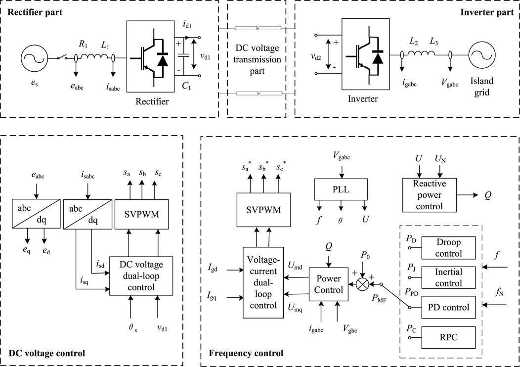
FIGURE 1. The VSC-HVDC system structure and its converter control structure.
At the sending end, the reactance L1 of the rectifier limits the rise of the short-circuit current; the capacitor C1 suppresses the DC voltage fluctuation. The VSC-HVDC system usually adopts a constant DC voltage control to effectively maintain the DC voltage stability; the inner loop tracks the VSC current change in real time, and the outer loop controls power and voltage. When the grid voltage is stable, by neglecting the power loss of the VSC itself, we have
Both vd1 and P are proportional to the d-axis component isd of the rectifier output current, according to which the control rule of the sending-end VSC can be obtained, as shown in Figure 2, where the active and the reactive power are decoupled and controlled separately. If the reactive power reference of the sending end VSC is set to 0, the inner loop can realize steady-state-error-free control to isd and isq Xie et al. (2014). In addition, since the rectifier realizes the DC voltage regulation, the VSC of the receiving-end grid only needs to track the dispatch instructions of the local grid; at the same time, it can be designed to additionally suppress the electromechanical oscillations and frequency fluctuations of the receiving-end grid.
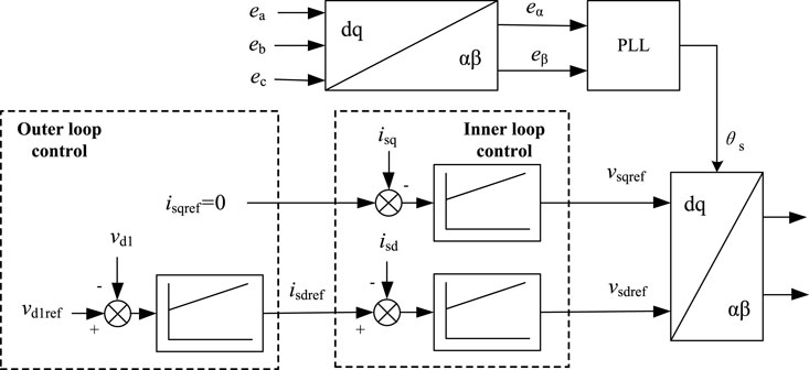
FIGURE 2. Control strategy of the sending-end converter of the VSC-HVDC system.
3 VSC-HVDC suppressing electromechanical oscillations and frequency fluctuations of receiving-end grid
To analyze the principle and strategy of the VSC-HVDC to suppress the electromechanical oscillations and frequency fluctuations of the receiving-end grid, this paper uses an equivalent SG to represent the receiving-end grid, as shown in Figure 3. In addition, to simulate the electromechanical oscillations of the rotor speed of the SG around the rated speed, the equivalent SG is operated in parallel with an infinite bus, so that the SG rotor speed is always clamped around the rated value. When it is necessary to simulate the frequency fluctuation where the frequency deviates from the rated frequency, the infinite bus system can be disconnected. With reference to Figure 3, Pm is the mechanical input power of the prime mover, Pe is the SG electromagnetic power, and Pv and Qv are the active- and reactive- power injected into the SG network by the VSC-HVDC. Iabc and Vabc are the current and voltage at the point of common coupling (PCC). U is the voltage between system two and the PCC, and E is the voltage between the SG and the PCC. Z1, Z2, Z3, and Z4 are equivalent impedances of corresponding lines.
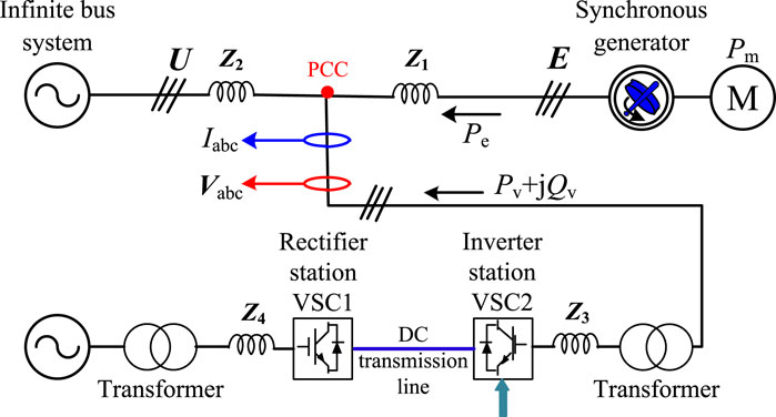
FIGURE 3. Integration of the HVDC into the system with oscillations and frequency fluctuations.
When suppressing the electromechanical oscillations and frequency fluctuations, the inverter VSC2 of HVDC usually adds the damping and the inertia control on top of the direct current control in Figure 4, where Id is the measured current and Iq is the measured reactive current; Idref and Iqref are the reference values of active and reactive currents, respectively. ω0 and ω denote the rated and detected values of rotor speed of the SG (oscillation suppression mode) or grid angular frequency (frequency control mode), respectively; kp1, kp2, kd1, and kd2 are gains of the P and D controllers corresponding to the active and reactive control loops, respectively.
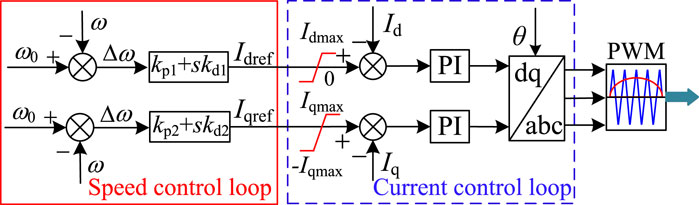
FIGURE 4. Control strategy of the VSC-HVDC to suppress oscillations and frequency fluctuations.
As can be seen from Figure 4, after coupling Idref and Iqref with the rotor speed (grid frequency), the power output of the VSC-HVDC system can be modulated quickly and independently, by controlling the reference values of active and reactive DC current components separately (on the d and q axes in the dq coordinate system), injecting controllable active and reactive power into the receiving-end network and improving the damping capacity and inertia effect of the system. The relevant principles and analysis can be found in Li et al. (2020).
Chi et al. (2019) points out that the damping control is based on the P controller to achieve power modulation, which helps to improve the damping capability of the system, and the inertia control is implemented with the help of the D controller to improve the system inertia. Also, the above strategies are conventional controls for grid-connected inverters to suppress electromechanical oscillations. Through the PI controller, Id and Iq can track their references, Idref and Iqref (Chi et al., 2019), and thus quickly and effectively regulate the active- and reactive- power from the VSC, finally realizing the suppression of electromechanical oscillations and frequency fluctuations of the receiving-end grid, and reducing the fluctuation range of the rotor speed and the grid frequency.
Based on the linearized model in Li et al. (2020), when the active- and reactive- power of the VSC-HVDC system are injected into the infinite system, the inertia coefficient TJ and the damping coefficient TD of the power system can be obtained respectively as
where D and H are the damping and inertia inherent to the power system; β and μ are the VSC2 control coefficients for active and reactive controls, respectively.
Obviously, the larger kd1 and kd2 are, the larger TJ is, the stronger the inertia provided to the grid, which can effectively suppress the rate of change of speed/frequency dω/dt; the larger kp1 and kp2 are, the larger TD is, which can effectively suppress the speed/frequency deviation Δω. However, when the grid suffers from a large disturbance resulting in a large dω/dt and Δω, to effectively suppress the power unbalance, a large range of power variations is required to be output by VSC (i.e., the PD controller gain should be increased), which may exceed the VSC2 design capacity S and power transmission limits shown in Figure 5.
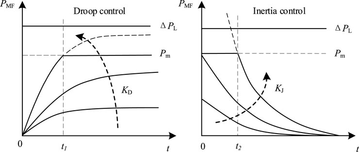
FIGURE 5. VSC power variation law under two typical control strategies.
If the current control dynamic in Figure 4 is ignored, the regulation power of the VSC in the receiving-end grid under the damping control, the inertia control, and the PD control can be roughly expressed as:
where KD is the damping control coefficient, KJ is the inertia control coefficient, and Kp and Kd are the proportional and differential coefficients of the PD controller, respectively.
Obviously, if the gains of the damping control, the inertia control, and the PD controller are reduced, the VSC regulation power can be reduced to prevent VSC overload protection, but at the same time, the inertia and damping of the power system at the receiving end will also be weakened. For this reason, the influence law of the PD controller gains on VSC power output is analyzed in this paper.
4 RPC mode of VSC-HVDC system
Assume that Im characterizes the maximum current of the VSC; Id max and Pmax are the Id limit and power transmission limit, respectively. Since VSC2 cannot absorb active power, the power and current values Pv, Qv, Id, and Iq shown in Figure 3 and Figure 4 satisfy the following constraints
With reference to Figure 6, where the HVDC operates with the damping control as an example, if kp is increased, the VSC active power will also gradually increase (with P0 being the steady-state output value of the VSC active power), and the VSC will operate in linear damping control and non-linear damping control modes, respectively. Among them, the non-linear control is caused when kp is amplified to a certain degree. When the rotor speed/grid frequency is greater than the rated value, the VSC active output value will be 0, as shown in Figure 6 for t1–t2; conversely, the VSC will output active power at the limit value Pmax.
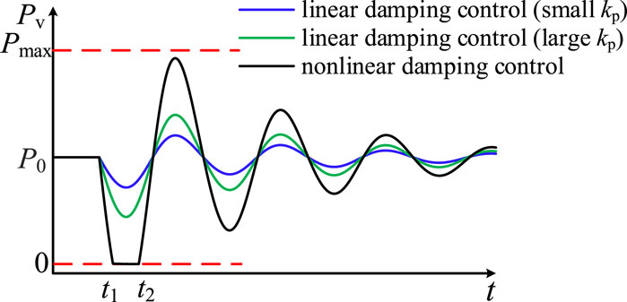
FIGURE 6. VSC active power output under different P controller gains.
Similarly, when the gain of D controller kd increases to a certain degree, the VSC will output active power at a constant value of 0 or Pmax for a specific period of time (i.e., the non-linear inertia control is used), and the controller will not be able to adjust the output power of the VSC.
The non-linear control is caused when the damping and inertia support of the HVDC are enhanced to a certain degree, and the ability of the non-linear control to suppress electromechanical oscillations and grid frequency fluctuations is also better than the damping and inertia control (Chi et al., 2019). Therefore, when kp1, kp2, kd1, and kd2 in the speed/frequency control are amplified to the limit, depending on the positive and negative polarity of the deviation, the power output of VSC2 in the full time range is:
1. Delivering constant active power alternately, using the active limit power Pmax of the inverter station VSC2 or 0 as the output reference;
2. Continuously absorbing or emitting constant reactive power with the remaining capacity of the inverter station as the limit value.
In this paper, the operation mode with the above two conditions of alternating constant power is referred to as the RPC mode of the VSC-HVDC system, which can maximize the suppression of grid electromechanical oscillations and frequency deviations. The theoretical analysis is shown as follows.
If the grid is under steady-state condition, then Pm and Pe are equal and the system power balance is met; if the grid load increases suddenly and the power change is ΔPm, a power shortage will occur, resulting in a continuous reduction in rotor speed/grid frequency (Δω = ω0−ω > 0). Therefore, the VSC-HVDC system should increase the active output or absorb reactive power to suppress the deceleration energy of the SG rotor and grid frequency.
If the VSC-HVDC system increases the active power by ΔPe, which yields 0 < ΔPe < ΔPm, the SG swing equation and the grid frequency response can be described as
As an example, if the VSC-HVDC system operates in the RPC control mode to regulate only the active power, then ΔPe = Pmax−P0. According to Eq. 9, we have
For VSC-HVDC to operate with the inertia control, the corresponding VSC active power should satisfy
Considering that at the starting moment when the power system suffers from electromechanical oscillations/grid frequency fluctuations (t = 0), |dω/dt| is its corresponding maximum value, while the VSC-HVDC has not yet generated additional active power to suppress the unbalanced active power of the system under the action of the control strategy, i.e., ΔPe = 0; at this time, |dω/dt|max is
If the VSC-HVDC is made to operate with the linear inertia control, the maximum D controller gain is
Eq. 9 and Eq. 13 show that: after the HVDC provides inertia to the grid using the inertia control (with the gain taking its maximum value), the rotor swing equation/grid frequency response equation can be described as
From Eq. 14, the value of |dω/dt| at this point is
Obviously, from the comparison of |dω/dt| shown in Eq. 10 and Eq. 15, it follows that
The comparison results of the rate of change of SG rotor speed and grid frequency under different control strategies [see Eq. 16] show that: in the case of the same maximum available VSC capacity, the suppression ability of the VSC-HVDC system based on the RPC control mode for dω/dt is significantly stronger than that of the linear inertia control strategy; similarly, the suppression ability of the VSC-HVDC system based on the RPC control mode for the speed/frequency deviation Δω is stronger than that of the conventional damping control strategy. The essential reason for the best regulation performance of the RPC strategy is that its supporting power to the receiving end grid can reach the maximum power output by the VSC. It should be noted that under the optimal control parameters, the oscillation suppression effect and grid frequency control effect of the PD control are equivalent to those of the RPC control, but the optimal PD control parameters are difficult to obtain. In contrast, the RPC control not only quickly compensates for the power shortage of the receiving end grid, but also avoids the problems of grid parameter measurement and controller parameter optimization. Table 1 summarizes the comparison of advantages and disadvantages between the RPC control strategy and the conventional control strategy.
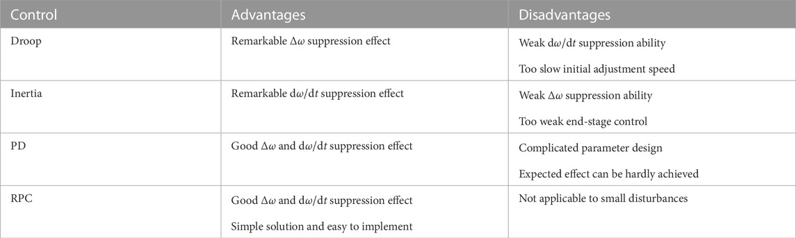
TABLE 1. Comparison of advantages and disadvantages between typical control strategies.
5 RPC based strategy for electromechanical oscillation suppression and frequency control
Based on the above analysis and conclusions, this paper integrates the respective advantages of the RPC mode and the damping control strategy, and proposes a coordinated active/reactive power control for the VSC-HVDC system to suppress grid oscillations and frequency fluctuations. With reference to Figure 7, the basic control and switching principles are:
1. If dω/dt and Δω are large, the VSC-HVDC system should switch to the RPC mode, to quickly compensate for system power shortage or suppress system excess power, and efficiently suppress Δω, dω/dt, and other speed indicators to avoid triggering the related relay protection devices of the power system. Under this mode, the VSC output active- and reactive- power should be switched to
2. When dω/dt and Δω meet the requirements, an additional damping control makes the VSC-HVDC system exit the RPC mode and gradually return to the power delivery mode, and continue to provide damping torque to reduce the oscillation area of the SG rotor and grid frequency.
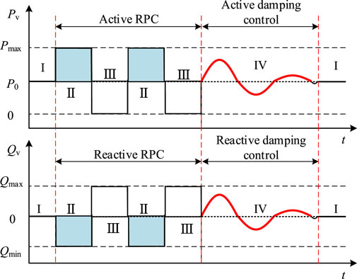
FIGURE 7. VSC-HVDC system power output under RPC mode.
The switching conditions and power commands corresponding to different conditions are discussed below. In the following discussion, ωd, ωth, and Rth are the thresholds of |Δω| and |dω/dt|, respectively, and 0 < ωd < ωth and Rth > 0. ωd is the |Δω| threshold for VSC switching to the damping control, ωth is the |Δω| threshold for VSC entering the RPC mode, and Rth is the |dω/dt| threshold for VSC switching to the RPC mode.
1. Condition I: When dω/dt and Δω are within the safety interval, i.e.,
the system is in steady state or the oscillations/fluctuations have been suppressed and the VSC should operate in steady-state transmission mode without adjusting its power output, i.e., P = P0, and Q = 0.
2. Condition II: If dω/dt and Δω simultaneously satisfy
then there is a serious power deficit in the grid, VSC-HVDC should increase the active power in time to compensate for this power deficit. Id should be immediately increased to Idmax, to provide continuous positive and fast active power compensation to the grid. At this time, P = Pmax to significantly suppress Δω and dω/dt. The remaining capacity of the inverter is used to absorb the grid reactive power to the maximum extent, regulate the PCC voltage, reduce the SG output power, and suppress the power angle increase. The reactive current Iq and Q commands are
3. Condition III: If dω/dt and Δω simultaneously satisfy
then there is a power surplus in the system. The VSC-HVDC system should immediately minimize the active output, i.e., Id should be immediately reduced to 0 in reverse, so that the active output P of the VSC-HVDC system is 0, while all the remaining capacity of the inverter station VSC2 will be used to transmit reactive power to the system, increasing the electromagnetic power of the SG, and providing reverse fast power compensation to the grid to suppress the active power surplus of the power system. At this time, the reactive current command of the current loop is set to Iq = −Im, and the reactive power of the inverter station is Q = S.
4. Condition IV: If the rotor speed indexes dω/dt and Δω satisfy
then the SG has a slight rotor oscillation phenomenon or a small range of grid frequency fluctuation. In order to ensure that the VSC-HVDC system delivers active power as much as possible, it should gradually return to the steady-state generation mode and switch to the damping control strategy of active/reactive power coordination to provide the necessary damping torque to the grid, suppressing the electromechanical oscillations and grid frequency fluctuations as much as possible and improving the frequency quality of the SG network. At this time, the active- and reactive- power at the inverter side of the VSC-HVDC system are set to be
When HVDC uses the RPC control to suppress large frequency fluctuations of the receiving-end grid caused by large disturbances, the relevant thresholds must strictly comply with the grid frequency indexes defined by the grid code, i.e., the frequency deviation Δf or the rate of change of frequency (RoCoF) df/dt. For example, GB/T 33593–2017, the grid integration standard for distributed energy sources in China, stipulates that the frequency deviation |Δf| shall not exceed 0.2 Hz during continuous operation, and shall not exceed 0.5 Hz when the relay action terminates power transmission. To ensure that the power grid can meet the above frequency index requirements under various disturbances, a necessary margin must be reserved for the HVDC system when it suppresses frequency fluctuations. Accordingly, the RPC based frequency control will be implemented according to Figure 8, where PC = Pm < ΔPL; if Δf or df/dt reaches the action threshold of the RPC control, the VSC power command is directly set to the maximum power capacity Pm. Similarly, when the grid frequency indexes decrease to the designed threshold, the VSC control mode switches to the damping control mode (i.e., droop control); when the grid frequency returns to the rated value, the VSC resumes the conventional constant power control mode. With reference to Figure 8, the three modes are autonomously switched according to the detected frequency of the receiving-end grid, to enhance the frequency fluctuation suppression effect and ensure the frequency stability of the receiving-end grid.
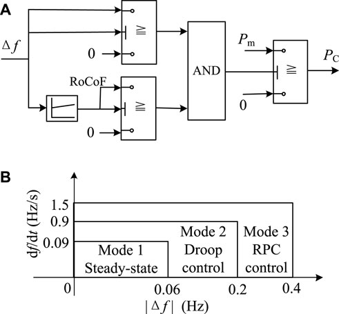
FIGURE 8. VSC frequency control based on RPC mode. (A) Control diagram. (B) Working mode switching.
Obviously, when electromechanical oscillations or frequency fluctuations occur in the sending-end grid, the rectifier can also adopt a similar method to make the VSC-HVDC system actively suppress the electromechanical oscillation process or frequency fluctuation problem in the sending-end grid.
6 Simulation verification
In this paper, the MATLAB/Simulink platform is used to compare and verify the suppression capability of the VSC-HVDC system against grid electromechanical oscillations and frequency fluctuations, when the RPC mode is combined with the damping control strategy. The simulation topology is shown in Figure 4.
6.1 Electromechanical oscillation suppression
The mechanical power of the prime mover of the receiving end grid changes abruptly at 5 s, causing an electromechanical oscillation. The VSC is made to operate in the absence of power control (kp = 0), and in the presence of conventional damping control (kp = 300) and non-linear damping control (kp = 700) by adjusting the P controller gain. The SG rotor speed under the above control strategies is compared with the coordination strategy proposed in this paper, and the simulation results are shown in Figure 9.
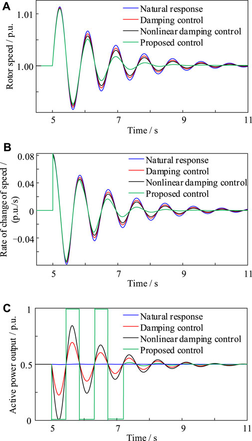
FIGURE 9. Oscillation suppression. (A) Rotor speed. (B) Rate of change of speed. (C) HVDC power.
As shown in Figures 9A,B, compared with the working condition of the VSC-HVDC system without power control (i.e., kp = 0), the electromechanical oscillation amplitude and the oscillation amplitude of SG rotor speed gradually decrease as the parameter kp increases. However, the rotor oscillation period does not change, indicating an almost unchanged inertia level despite the fact that the grid damping capability is enhanced. The corresponding active power output waveforms of the inverter station VSC2 under different control strategies are given in Figure 9C. Note that in this case Δω is small when switching to the damping control strategy to modulate the power output, and therefore kp can be appropriately amplified (here the value is taken as 1,000).
It can be concluded that the linear damping control strategy is not conducive to enhancing the ability of the VSC-HVDC to suppress the grid electromechanical oscillation. When the coordinated suppression strategy proposed in this paper is adopted, the SG rotor recovers to its rated speed significantly faster, and the amplitude of rotor oscillation is significantly reduced. At the same time, the rotor speed variation rate dω/dt is substantially suppressed. This indicates that the oscillation suppression effect of the proposed strategy is stronger than that of the damping control and the local RPC strategy.
6.2 Frequency fluctuation suppression
In this simulation scenario, the infinite bus in Figure 3 is removed to simulate the capacity-limited receiving end grid. To simulate the operating condition where the power grid is subject to small disturbances, a disturbance of 0.1 p.u. Is suddenly added to the receiving end power grid at t = 30 s, when the droop control starts frequency control (see Figure 10). Under the condition of small disturbance, the frequency deviation using the droop control is reduced by 0.09 Hz compared with the natural response, the maximum value of the rate of change of frequency (RoCoF) is 0.14 Hz/s smaller than that of the natural response, and the compensation power to the receiving-end grid is significantly increased. It can be seen that the suppression effect of the droop control on frequency deviation is more prominent than that of RoCoF. At this time, the frequency is within the allowable range of the system during steady-state operation, and the HVDC system can smoothly exit the droop control mode.
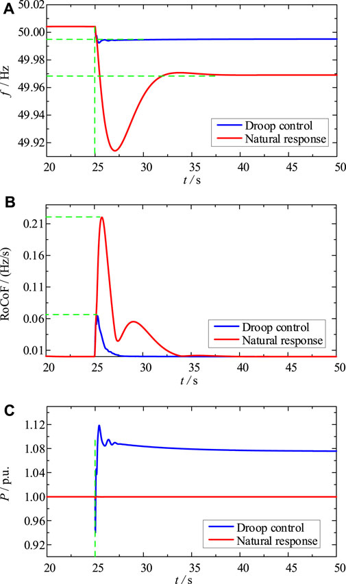
FIGURE 10. Frequency control under small disturbance. (A) Grid frequency. (B) RoCoF. (C) Inverter power.
To simulate the large disturbance, a disturbance of 0.9 p.u. Is suddenly added to the receiving end grid at t = 25 s (see Figure 11). The simulation results show that: with the proposed strategy, the HVDC system can adjust the operation mode autonomously, and quickly compensate for the power shortage of the receiving-end grid; the frequency of the receiving-end system is stabilized to 49.96 Hz within 3 s, and the maximum RoCoF is only 0.15 Hz/s. Conversely, under the same interference condition, the frequency control capability of the droop control is extremely limited. Obviously, the RPC control has a strong suppression effect on both frequency deviation and RoCoF.
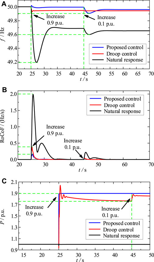
FIGURE 11. Frequency control under hybrid disturbance. (A) Grid frequency. (B) RoCoF. (C) Inverter power.
The adaptive performance of the proposed HVDC control is further tested by adding a disturbance of 0.1 p.u. at t = 45 s. The test results (see Figure 11) show that the proposed control strategy can ensure that the HVDC system can autonomously sense the frequency change trend of the receiving end grid under different disturbance conditions, adjust the inverter operation mode, and continuously and dynamically match the real-time operating condition of the receiving-end power grid to always effectively suppress its frequency fluctuation problem.
7 Conclusion
Under the VSC capacity constraints, this paper compares the suppression level of rotor speed and frequency change rate for HVDC operating in the RPC mode and with the linear control. HVDC operating in the RPC mode has significantly suppression ability of electromechanical oscillations and frequency fluctuations. Then, this paper integrates the RPC mode and the damping control, and designs four operating conditions and power commands to regulate the HVDC power. The proposed active/reactive power coordination strategy, based on the RPC mode, can quickly suppress the system power imbalance and significantly improve the suppression effect of the HVDC on electromechanical oscillations and frequency fluctuations. Simulation results show that the supporting power introduced by the conventional control and its response speed are much smaller than the shortage power required when the grid is disturbed. Conversely, the RPC control can fully utilize the VSC power reserve, quickly and sufficiently compensating for the lack power, stabilizing the grid frequency in time and effectively suppressing the electromechanical oscillation.
Data availability statement
The original contributions presented in the study are included in the article/supplementary material, further inquiries can be directed to the corresponding author.
Author contributions
All the authors conceived and designed the study. CB, JW, and YQ performed the simulation. CB, JW, and XL conceived and designed the simulations. YQ and JX wrote the manuscript with the guidance from JS and FL.
Conflict of interest
CB, JW, XL, JX, and FL were empolyed by Guangzhou Power Supply Bureau, Guangdong Power Grid Co., Ltd.
The remaining authors declare that the research was conducted in the absence of any commercial or financial relationships that could be construed as a potential conflict of interest.
Publisher’s note
All claims expressed in this article are solely those of the authors and do not necessarily represent those of their affiliated organizations, or those of the publisher, the editors and the reviewers. Any product that may be evaluated in this article, or claim that may be made by its manufacturer, is not guaranteed or endorsed by the publisher.
References
Ali, H., Magdy, G., Li, B., Shabib, G., Elbaset, A. A., Xu, D., et al. (2019). A new frequency control strategy in an islanded microgrid using virtual inertia control-based coefficient diagram method. IEEE Access 7, 16979–16990. doi:10.1109/ACCESS.2019.2894840
Chi, Y., Tang, B., Hu, J., Tian, X., Tang, H., Li, Y., et al. (2019). Overview of mechanism and mitigation measures on multi-frequency oscillation caused by large-scale integration of wind power. CSEE J. Power Energy Syst. 5, 433–443. doi:10.17775/CSEEJPES.2019.01100
Fang, J., Tang, Y., Li, H., and Li, X. (2018). A Battery/Ultracapacitor hybrid energy storage system for implementing the power management of virtual synchronous generators. IEEE Trans. Power Electron. 33, 2820–2824. doi:10.1109/TPEL.2017.2759256
Kerdphol, T., Watanabe, M., Hongesombut, K., and Mitani, Y. (2019). Self-adaptive virtual inertia control-based fuzzy logic to improve frequency stability of microgrid with high renewable penetration. IEEE Access 7, 76071–76083. doi:10.1109/ACCESS.2019.2920886
Kumar, A. (2016). Power system stabilizers design for multimachine power systems using local measurements. IEEE Trans. Power Syst. 31, 2163–2171. doi:10.1109/TPWRS.2015.2460260
Kundur, P., Paserba, J., Ajjarapu, V., Andersson, G., Bose, A., Canizares, C., et al. (2004). Definition and classification of power system stability IEEE/CIGRE joint task force on stability terms and definitions. IEEE Trans. Power Syst. 19, 1387–1401. doi:10.1109/TPWRS.2004.825981
Lee, H.-Y., Asif, M., Park, K.-H., and Lee, B.-W. (2018). Feasible application study of several types of superconducting fault current limiters in HVDC grids. IEEE Trans. Appl. Supercond. 28, 1–5. doi:10.1109/TASC.2018.2799745
Li, C., Wu, Y., Sun, Y., Zhang, H., Liu, Y., Liu, Y., et al. (2020a). Continuous under-frequency load shedding scheme for power system adaptive frequency control. IEEE Trans. Power Syst. 35, 950–961. doi:10.1109/TPWRS.2019.2943150
Li, M., Xiong, L., Chai, H., Xiu, L., and Hao, J. (2020b). Mechanism of PV generation system damping electromechanical oscillations. IEEE Access 8, 135853–135865. doi:10.1109/ACCESS.2020.3011456
Ling, Y., Li, Y., and Xiang, J. (2021). Load support by droop-controlled distributed generations. IEEE Trans. Ind. Electron. 68, 8345–8355. doi:10.1109/TIE.2020.3013764
Liu, X., Spadacini, G., and Pignari, S. (2020). Physically based modeling of hand-assembled wire bundles for accurate emc prediction. IEEE Trans. Electromagn. Compat. 62, 914–922. doi:10.1109/temc.2019.2922455
Liu, X., Wu, B., and Xiu, L. (2022a). A fast positive-sequence component extraction method with multiple disturbances in unbalanced conditions. IEEE Trans. Power Electron. 37, 8820–8824. doi:10.1109/TPEL.2022.3161734
Liu, X., Xiong, L., Wu, B., Qian, Y., and Liu, Y. (2022b). Phase locked-loop with decaying DC transient removal for three-phase grids. Int. J. Electr. Power & Energy Syst. 143, 108508. doi:10.1016/j.ijepes.2022.108508
Nguyen, H. T., Yang, G., Nielsen, A. H., and Jensen, P. H. (2019). Combination of synchronous condenser and synthetic inertia for frequency stability enhancement in low-inertia systems. IEEE Trans. Sustain. Energy 10, 997–1005. doi:10.1109/TSTE.2018.2856938
Peng, Q., Yang, Y., Liu, T., and Blaabjerg, F. (2020). Coordination of virtual inertia control and frequency damping in PV systems for optimal frequency support. CPSS Trans. Power Electron. Appl. 5, 305–316. doi:10.24295/CPSSTPEA.2020.00025
Shi, Q., Liu, L., Wang, Y., Lu, Y., Zou, Q., Zhang, Q., et al. (2021). Cooperative synthetic inertia control for wind farms considering frequency regulation capability. Front. Energy Res. 9, 738857. doi:10.3389/fenrg.2021.738857
Sun, K., Xiao, H., Liu, S., and Liu, Y. (2021). Machine learning-based fast frequency response control for a VSC-HVDC system. CSEE J. Power Energy Syst. 7, 688–697. doi:10.17775/CSEEJPES.2020.01410
Varma, R. K., and Maleki, H. (2019). PV solar system control as STATCOM (PV-STATCOM) for power oscillation damping. IEEE Trans. Sustain. Energy 10, 1793–1803. doi:10.1109/TSTE.2018.2871074
Wang, J., Huang, M., Fu, C., Li, H., Xu, S., and Li, X. (2019). A new recovery strategy of HVDC system during AC faults. IEEE Trans. Power Deliv. 34, 486–495. doi:10.1109/TPWRD.2019.2892410
Wang, Y., Meng, J., Zhang, X., and Xu, L. (2015). Control of PMSG-Based wind turbines for system inertial response and power oscillation damping. IEEE Trans. Sustain. Energy 6, 565–574. doi:10.1109/TSTE.2015.2394363
Xie, Y., Huang, J., Liu, X., Zhuo, F., Liu, B., and Zhang, H. (2014). “Pv system modeling and a global-planning design for its controller parameters,” in 2014 IEEE Applied Power Electronics Conference and Exposition, Fort Worth, TX, USA, 16-20 March 2014 (IEEE), 3132–3135.
Xiong, L., Liu, L., Liu, X., and Liu, Y. (2021a). Frequency trajectory planning based strategy for improving frequency stability of droop-controlled inverter based standalone power systems. IEEE J. Emerg. Sel. Top. Circuits Syst. 11, 176–187. doi:10.1109/JETCAS.2021.3052006
Xiong, L., Liu, X., Liu, H., and Liu, Y. (2022). Performance comparison of typical frequency response strategies for power systems with high penetration of renewable energy sources. IEEE J. Emerg. Sel. Top. Circuits Syst. 12, 41–47. doi:10.1109/JETCAS.2022.3141691
Xiong, L., Liu, X., and Liu, Y. (2021b). Decaying dc and harmonic components detection for absorbing impact load currents in weak grids. IEEE Trans. Power Deliv. 36, 1907–1910. doi:10.1109/TPWRD.2020.3038077
Xiong, L., Zhuo, F., Liu, X., Zhu, M., Chen, Y., and Wang, F. (2015). “Research on fast open-loop phase locking scheme for three-phase unbalanced grid,” in 2015 IEEE Applied Power Electronics Conference and Exposition (APEC), Charlotte, NC, USA, 15-19 March 2015 (IEEE), 1672–1676.
Xu, Y., and Wang, H. (2021). Torque limit-based inertial control of a dfig for rapid frequency stabilization. Front. Energy Res. 9, 788989. doi:10.3389/fenrg.2021.788989
Yang, D., Sang, S., and Zhang, X. (2021). Two-phase short-term frequency response scheme of a dfig-based wind farm. Front. Energy Res. 9, 781989. doi:10.3389/fenrg.2021.781989
You, J., Xu, D., and Cao, J. (2022). Dynamic power-based temporary frequency support scheme for a wind farm. Front. Energy Res. 10, 1005796. doi:10.3389/fenrg.2022.1005796
Zhang, L., Harnefors, L., and Nee, H. P. (2011). Interconnection of two very weak AC systems by VSC-HVDC links using power-synchronization control. IEEE Trans. Power Syst. 26, 344–355. doi:10.1109/TPWRS.2010.2047875
Keywords: VSC-HVDC, grid electromechanical oscillations, grid frequency control, rapid power compensation, damping control
Citation: Bi C, Wu J, Qian Y, Luo X, Xie J, Shi J and Luo F (2022) Power optimization control of VSC-HVDC system for electromechanical oscillation suppression and grid frequency control. Front. Energy Res. 10:1089465. doi: 10.3389/fenrg.2022.1089465
Received: 04 November 2022; Accepted: 28 November 2022;
Published: 14 December 2022.
Edited by:
Liansong Xiong, Xi’an Jiaotong University, ChinaReviewed by:
Yongbin Wu, Southeast University, ChinaYue Wang, Xi’an Jiaotong University, China
Yonghui Liu, Hong Kong Polytechnic University, Hong Kong SAR, China, in collaboration with reviewer YW
Zhenxiong Wang, Xi’an Jiaotong University, China
Lei Liu, School of Electrical Engineering, Xi'an Jiaotong University in collaboration with reviewer ZW
Copyright © 2022 Bi, Wu, Qian, Luo, Xie, Shi and Luo. This is an open-access article distributed under the terms of the Creative Commons Attribution License (CC BY). The use, distribution or reproduction in other forums is permitted, provided the original author(s) and the copyright owner(s) are credited and that the original publication in this journal is cited, in accordance with accepted academic practice. No use, distribution or reproduction is permitted which does not comply with these terms.
*Correspondence: Jianquan Shi , shijianquan@njit.edu.cn