Design of a soft-contact triboelectric nanogenerator for vibrational energy collection and its output performance
 Jin Yan1,2
  Naerduo Mei
 Dapeng Zhang
- 1Guangdong Ocean University, Zhanjiang, China
- 2Shenzhen Research Institute of Guangdong Ocean University, Shenzhen, China
Finding renewable energy sources to lower carbon emissions has emerged as a challenge the world faces in the wake of global warming and energy crises. Vibration is a type of mechanical motion common in daily life, and one popular research topic in this regard is how to gather vibrational energy and transform it into electricity. Vibration energy can be collected using triboelectric nanogenerators whose working mechanism is based on contact electrification and electrostatic induction. The COMSOL software is used to simulate the relationship between the voltage across electrodes, transferred charge, and the electrode moving distance (V-Q-X) of triboelectric nanogenerator. Theoretical analysis of the simulation result is offered, along with a brief description of the simulation procedure. When wool is glued to the inner core aluminum foil, TENG’s output performance is significantly improved, with a maximum open-circuit voltage of 160 V. In addition, TENG’s output performance improves linearly as the vibration frequency and amplitude increase. Specifically, when the vibration frequency rises from 1 to 2.5 Hz, the open-circuit voltage rises from 43 to 100 V, the short-circuit current increases from 0.45 to 1.5 µA, and the peak transfer charge grows from 23 to 46 nC; when the vibration amplitude increases from 30 to 60 mm, the maximum open-circuit voltage increases from 50 to 110 V, the maximum short-circuit current increases from 0.3 to 1.5 µA, and the maximum charge transfer increases from 21 to 54 nC. Durability tests of TENG shows that the soft-contact TENG with wool adhesives is exceptionally durable, with decreased mechanical wear on the contact surface and extended service life. The present work is expected to provide some insight into the working mechanism of low-loss and high-performance TENGs and facilitate their wider adoption.
1 Introduction
Demand for energy has been growing with the fast advances of the modern world (Lin et al., 2016; Cheng et al., 2019; Lin et al., 2020). Despite the many conventional energy sources developed in the past (Chen et al., 2015; Bera, 2016; Liu et al., 2021a), the development process suffers such problems as expensive raw materials, limited resources, and threats to environmental pollution (Cao et al., 2016; Liu et al., 2021b; Wang, 2021), making it an urgent need to develop energy sources that are both economical and environmentally-friendly. To meet this need, researchers are now shifting to natural energy sources to produce electricity through friction.
The friction nanogenerator (TENG), which can effectively convert mechanical energy into electrical energy and output (Yu et al., 2012; Jing et al., 2014; Yang et al., 2014; Guo et al., 2017; Wang et al., 2017; Xu et al., 2018; Wu et al., 2019; Zhao et al., 2019; LIANG et al., 2020; Xia et al., 2020; Zhang et al., 2020) it as an electrical signal through frictional initiating effect and electrostatic induction coupling, was first proposed by Prof. Zhonglin Wang’s team in 2012. The triboelectric nanogenerator (TENG), which is now witnessing quick development and updating (Zhang et al., 2019a; Khandelwal et al., 2020; Long et al., 2021), has been intelligently coupled with various energy sources including wave energy (Xu et al., 2018; Rodrigues et al., 2020), wind energy (Li et al., 2021a; Li et al., 2021b; Liu et al., 2021c; Li, 2022a; Li, 2022b), solar energy (Zheng et al., 2022), vibration energy (Yang et al., 2013; Quan et al., 2015; Chen and Wang, 2017; Wu et al., 2017), body movement energy (Xia et al., 2018; Zhang et al., 2019a; Xia et al., 2019), Liquid-solid interactions (Jang et al., 2020; Jang et al., 2022; Yoo et al., 2022), just to name a few. And to make better use of these energies, researchers are making unremitting efforts to enhance the electrical output performance of TENG in terms of material surfaces (Chen et al., 2020; Zhou et al., 2020), structure optimization (Niu et al., 2014; Feng et al., 2021; Nurmakanov et al., 2021; Yun et al., 2021), and management circuits (Qin et al., 2018). Meanwhile, a number of TENGs have been developed and used to portable electronics (Zhang et al., 2019b), sensors (Wang et al., 2015), and biomedical systems (Zheng et al., 2017) to meet the demand for energy and environmental adaptability in many domains. The closeness of the contact between the frictional electrodes determines a TENG’s output performance. A higher friction between frictional surfaces can result in material degradation and reduced durability of the device, but closer contact can generate more frictional charge and better output performance. Therefore, it is crucial to find ways to improve the TENG’s stability, decrease wear, and increase durability without sacrificing output performance. Zhang et al. (Zhang et al., 2020) designed a non-contact cylindrical rotating TENG to recover mechanical energy from hydraulic systems, and its operating mechanism is based on the non-contact free rotation of a flexible nanowire (NW) structure and a copper foil curve, or more specifically, the rotation of a flexible nanowire (NW) structure of a fluorinated ethylene-propylene (FEP) polymer sheet in non-contact with a bent copper foil, though the TENG’s output performance is still constrained by the TENG’s limited contact area and charge. Li et al. (Li et al., 2021c) have presented a polyester fur-reinforced rotating triboelectric nanogenerator (PFR-TENG) with ultra-stable high voltage output, where a soft polyester fur layer is introduced as a charge pump and charge emitter to form partial soft-contact and non-contact based on the proper work function and electronegativity. Though the non-contact TENG has less losses in the friction layer, its output is not stable and its structure is complicated. To reduce the loss, Li et al. (Long et al., 2021) presented a floating self-excited sliding TENG (FSS-TENG) with a floating mode and a non-contact TENG air breakdown model. The FSS-TENG achieves a self-increased charge density by self-excited amplification between the rotor and stator; the minimum of transmitted charge, however, remains a significant issue. These studies offer helpful suggestions for enhancing the TENG’s output performance, stability, and wear resistance during extended periods of operation.
2 Experiment
2.1 Design and modelling of the TENG
Figure 1A depicts a perspective view of the interior and an external model of the TENG. As PTFE is more electronegative than other materials due to its different position in the frictional electric sequence, PTFE is more likely to lose electrons than other materials and as a result has a higher capacity for charge transfer and higher output performance. The main structure of the TENG is made up of a shell with aluminum foil and PTFE film attached to the inner surface in sequence. For this reason, the upper electrode and dielectric are made of aluminum foil and PTFE, respectively. As the lower electrode, an aluminum foil is put to the outside surface of the core, and wool is then attached on top of the foil as an additional material. Wool is a more ideal additional material since it is more readily available, more electronegative, and softer than other materials. The two friction layers of the TENG become electrically charged when it moves horizontally, with the PTFE foil being electronegative and the wool being electrically positive. The TENG’s operating signals, which are high voltage and low current, can be gathered.
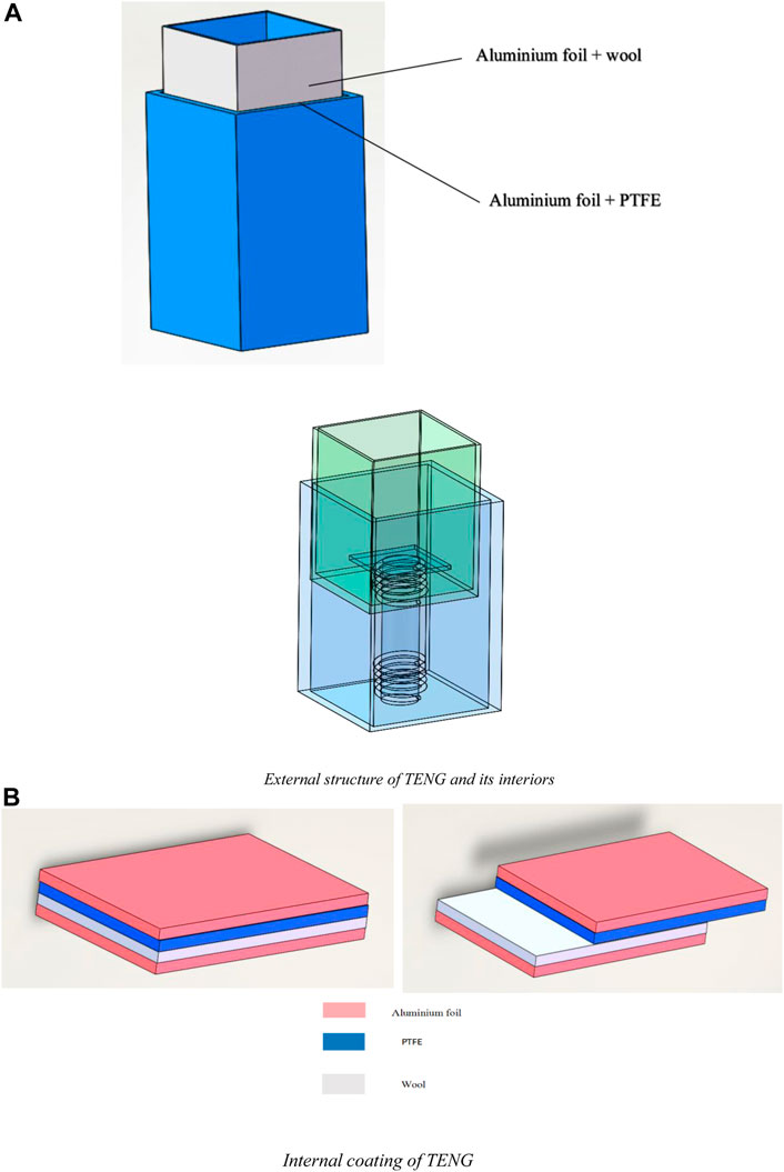
FIGURE 1. Structure and internal coating of the TENG. (A) External structure of TENG and its interiors. (B) Internal coating of TENG.
A fundamental model of a TENG with a horizontal sliding structure is created (Figure 1), which successfully separates the two friction layers under various external stresses, as shown in Figure 1A. The proposed TENG comprises of a cylindrical structure inside the shell connected to a hollowed inner rectangular core. A steel spring is installed to the top and bottom of the cylindrical structure, giving the inner core more strength so it can rub more thoroughly. This pillar system passes through a circular hole at the bottom of the core connected to the shell. To prevent the core from ejecting from the shell when force is applied and to limit the movement of the core to the top of the cylindrical structure, an acrylic sheet is glued to the top of the cylinder after the cylindrical structure and the inner core are linked. Figure 1 2) shows the internal coating of the Teng. The aluminum foil and the PTFE film, which serve as the upper electrode and dielectric, are bonded on the interior surface of the shell; as the bottom electrode, the aluminum foil is laminated onto the outer surface of the inner core, and wool is added as a support material on the outside of the electrode. The high voltage and low current produced during operation are collected by the TENG.
2.2 TENG test platform
Figure 2 shows the test rig for TENG’s output performance. First, the linear motor is connected and fixed to the optical plate; next, the TENG is connected to the linear motor and fixed to the linear motor push plate before controlling the linear motor via the computer. The linear motor software LinMot-Talk can only set the acceleration, speed, and displacement, so the linear motion formula needs to be derived to calculate the displacement and acceleration at different frequencies and amplitudes. For data collection, the acceleration and displacement parameters are configured to control the linear motor; meanwhile, the positive and negative electrodes are connected by two wires to the positive and negative contacts on the Keithley 6,514 electrostatic meter, which converts the received digital signals such as voltage, current, and charge into analogue signals and then transmits them to the NI voltage acquisition card. The sampling frequency is set to 500 by the LabView software for data storage, and then the collected data are processed and analyzed to obtain the experiment results.
1) Keithley 6,514 electrostatics meter: input impedance up to 200TΩ, high sampling rate, dynamic current, voltage, and charge acquisition in real time, combined with high-speed voltage acquisition card and system software makes the acquisition signal can reach a maximum speed of 50,000 points per second, with voltage measurement ranges of 10 μV-200V, and current measurement ranges of 1fA-20mA. Friction nanogenerators’ high output voltage and low output current electrical output features.
2) Data acquisition equipment: A voltage acquisition card, model NI-9215, with four simultaneous acquisition channels, a 100 kS/S acquisition rate per channel, a 16-bit resolution, built-in signal conditioning, and a USB connection to the PC without an external power source is used for data acquisition. The voltage acquisition card receives the electrostatic meter’s converted analogue signal during the data acquisition process, which then displays the signal on the PC hooked up to the card to display the measurement results.
3) Linear motor: In the experiment, a linear motor is used to replicate the motion of the wave. The LinMot-E1200-RS type, with a top speed of 3.2 m/s, a top thrust of 163 N, and a stroke of 360 mm, was selected for the linear motor. The output current can also be used to control different thrust sizes. The requirements of this experiment are entirely satisfied by the linear motor, which satisfies the wave’s low frequency and low amplitude properties.
4) 3D printer: UItinaker three model, a professional-grade 3D printer with a dual printhead design, long uptime, water-soluble support, quick nozzle swapping, sticky 3D printing ecosystem, and interconnected cohesiveness. The print medium is PLA (Polylactic Acid), which has a wire diameter tolerance of 0.03 mm and a tensile strength of 250 kg/cm2, a melting point of 160–165°C and a wire diameter tolerance of 0.03 mm. SOLIDWORKS was used to create the inner and exterior boat structure, which was then imported into CURA for slicing and manufactured using a 3D printer.
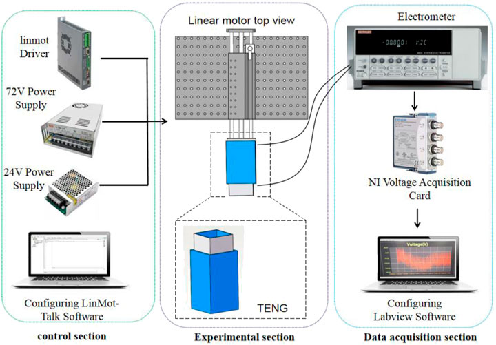
FIGURE 2. Schematic diagram of the TENG output performance test rig.
3 Theoretical analysis
3.1 Principle of operation
Figure 3 shows one complete cycle of the TENG in operation, and Figure 3A describes the state at which no mechanical forces are applied and there is no relative displacement of the fleece-bonded aluminum foil from the PTFE film. Since the frictional charge is distributed only on the surface layer of the polymer that is well insulated, no charge leakage occurs during one cycle. At the initial position, the distance between the positively and negatively charged surfaces is negligible, so there is hardly any potential difference between the two electrodes. As shown in Figure 3B, once the positively charged upper electrode plate starts to slide outwards, the contact area between the two plates decreases, resulting in separation of charges on the plane and hence a higher potential of the upper plate. In this case, electrons flow from the upper electrode to the lower electrode to offset the potential difference created by the frictional charge. Ideally, the vertical distance between the electrode layer and the friction charge surface is negligible compared to the lateral separation distance of the charges, so the amount of transferred charge at the electrode is approximately equal to the amount of charge separated at any sliding position. Therefore, as the sliding process proceeds, the charge will continue to flow so that the separated charge increases, until the upper plate slides completely away from the lower plate and the frictional charge surfaces are completely separated, as shown in Figure 3C, where the test value of the current is determined by the sliding speed of the two plates. Subsequently, when the upper plate slides back in, as shown in Figure 3D, the separated charges are again in contact with each other but not annihilated due to the insulating nature of the polymer material. As the contact area increases, the excess of the electrode transfer charge is induced to flow from the lower electrode back to the upper electrode via an external load to maintain electrostatic equilibrium. This process is the second half of the sliding process. When the two plates return to the overlapping position, the charged surfaces are again in full contact with each other. At this point, there is no remaining transfer charge at the electrodes and the device returns to the state shown in Figure 3A. Throughout the cycle, the outward and inward sliding processes are symmetrical and therefore a symmetrical pair of AC current peaks will be obtained.
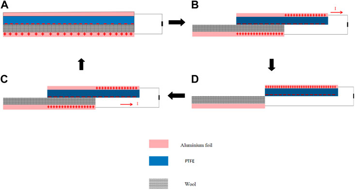
FIGURE 3. Schematic diagram of an operation cycle of TENG.
3.2 Electrical performance simulation by comsol multiphysics
To describe the operating principle of the double-layer soft-contact TENG, the COMSOL simulation software, which specializes in multi-physics field coupling, was used to model, mesh and simulate the potential distribution of the friction material under different conditions.
First, a two-dimensional geometric model of the TENG was created using COMSOL (Figure 4), and different materials were added to the material library for different geometries, with the dielectric material set as PTFE, the thickness set to 1 mm and the Poisson’s ratio set to 0.3. The surface metal of the inner and outer structures and the two electrodes were set as aluminum, and the width of both electrodes was set to 1 mm. To simplify computation, the simulation was set to a steady-state calculation. To obtain the trend in the potential, the charge density on the PTFE surface was set to −0.02 μC/m2 and the total charge density on the aluminum surface was set to 0.01 μC/m2.
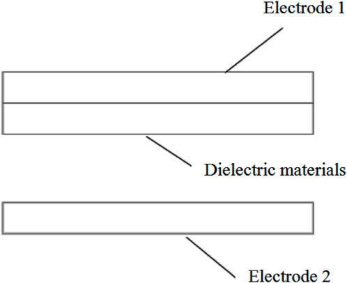
FIGURE 4. TENG geometric model.
Next, after the geometric model was built and material settings were completed, the geometry was meshed, as shown in Figure 5, The mesh was predefined and set to “finer”. For all materials, a free triangular mesh is selected, and the air-domain mesh was set to “very fine” with a maximum cell size of 0.4 mm and a minimum cell size of 5 × 10⁻³ mm, since air has a small effect on the induced potential distribution in this geometry. For the electrodes, separate metals and dielectric materials in contact with each other, the mesh was set to “superfine” with a maximum cell size of 0.04 mm and a minimum cell size of 3 × 10⁻⁴ mm. As Figure 5 shows, the mesh size for the air gap is larger, and the mesh is finer as it gets closer to the electrodes, the separate metals, and the dielectric materials that are the contact parts.
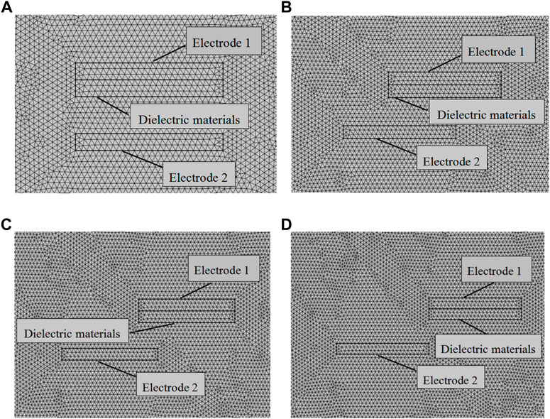
FIGURE 5. Geometric meshing of TENG.
Finally, using Maxwell’s control equations, the potential distribution between the two electrodes at different spacings can be calculated using finite element simulations, as shown in Figure 6, which clearly shows the potential difference between the two electrodes. At the initial state, the aluminum electrode is in full contact with the PTFE (Figure 6A) and charge transfer occurs between the two. As the two begin to move away from each other (Figure 6B), an electric field is formed between the electrodes and the air gap, creating an electric potential difference between the upper and lower electrodes and, as can be seen from the potential cloud, the potential difference between the two electrode surfaces increases with the increasing horizontal displacement. This is consistent with the linear variation of the potential difference with the separation distance, as previously mentioned. When the separation distance reaches a maximum (Figure 6D), the potential difference is at its maximum. As the separation distance decreases from the maximum (Figure 6C), the potential difference decreases as well. It should be noted that the separation distance should not be set too large during simulation; otherwise, the edge effect will have a significant impact and make the electric field line become approximately an electric field line between two point charges, rather than a uniform electric field. The simulation result shows that the trend of the potential distribution is consistent with the working principle of TENG.
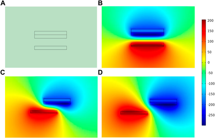
FIGURE 6. TENG simulation potential distribution.
3.3 Theoretical foundations
In the present work, a horizontal sliding TENG V-Q-X model is developed, as shown in Figure 7. Under ideal conditions, the length and width of the dielectric are much greater than its thickness, so that edge effects are negligible. The metal plate one is not only the top friction layer, but also the top electrode itself. When the metal plate one is separated from the dielectric 2, a frictional charge with a charge density of −σ is uniformly distributed on the top surface of the separated area of the dielectric two due to the frictional start effect, while an equal amount of negative frictional charge is distributed on the surface of the metal plate 1. Thus, under open-circuit conditions (where the charge reference state can reach a minimum), the total charge at the bottom electrode is 0. To facilitate understanding, the frictional charge in the overlap region of the dielectric surface can be regarded as the portion of the top metal layer with a charge density of σ. The total amount of anti-signal frictional charge of σw(l-x) is removed.
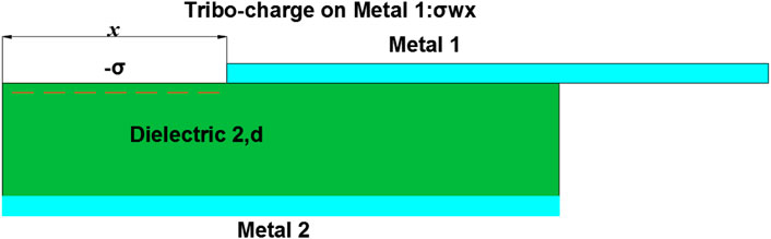
FIGURE 7. TENG Theoretical models.
In general, it is impossible to derive an analytical equation for the sliding TENG with attached electrodes, but a rigorous theoretical analysis based on numerical calculations is feasible. In practice, the lateral separation distance x is always less than 0.91 L, considering that l is always far larger than d1 and d2, and that it is difficult to align the two dielectric surfaces precisely again after complete separation of the two dielectrics. First, the intrinsic capacitance C is derived, and since the thickness of the dielectric is much smaller than its length, the total capacitance is determined by the capacitance between the overlapping regions as long as the two dielectrics do not reach a complete separation. Therefore, using the parallel plate capacitor model, the total capacitance C can be estimated by the following equation:
where d0 is the effective thickness constant.
The value of Voc is then estimated from the charge distribution. Since the length of the dielectric is much larger than its thickness, it can be assumed that in each region, the metal electrodes are infinitely large flat plates. By this approximation, the charge in each region is uniformly distributed and the electric field inside the dielectric is uniformly distributed along the y-axis. This conclusion can also be verified by the result of finite element calculations. Thus, in the ideal case, the absolute value of charge density on the surface of the non-overlapping region is σ. While the charge density in the overlapping region is still uniformly distributed, the charge density in the overlapping region can be calculated by taking the total charge on each electrode as 0 in the open-circuit condition. The ideal charge distribution under open-circuit conditions (where the charge reference state can reach the minimum) can be approximated by the following equations:
For the un-overlapped area of the bottom electrode, the charge density is:
For the overlapping area of the bottom electrode:
For the un-overlapped area of the top electrode:
For the overlapping area of the top electrode:
Using the above charge distribution law and the Gauss theorem, the analytical expression for the open-circuit voltage Voc can be estimated:
Thus, when the edge effect is neglected, the V-Q-X relationship for the sliding TENG with attached electrodes is:
4 Discussion of experimental results
4.1 Comparison of output performance of TENG with and without supplementary materials
Figure 8 shows a comparison of the performance of the TENG with and without the supplementary material wool. Two types of cores were chosen for the test: one with wool on the outer aluminum foil, and one without. The output performance of the TENG with wool is much higher than that of the TENG without, as shown in Figures 8A–C. Specifically, the TENG with wool as the supplementary material achieves an open-circuit voltage and peak transfer charge two times higher than that without, reaching a maximum open-circuit voltage of 160 V and a peak charge of 72 nC. The peak short-circuit current is more than three times higher, reaching 1.5 µA. This is because in the TENG without wool, there is no contact between the core and the shell.
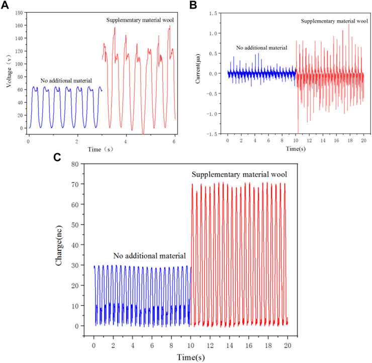
FIGURE 8. Output performance of TENG with and without supplementary materials. (A)Open-circuit voltage; (B) Short-circuit current; (C)Transfer of charge.
4.2 Effect of frequency on TENG output performance
The TENG output performance was investigated within the frequency range of 1–2.5 Hz and at a fixed amplitude of 50 mm, with the internal structural conditions kept constant, i.e., a wool-glued inner core was selected and PTFE of 0.3 mm thickness was used as a dielectric film.
Figure 9 shows the experiment result. The open-circuit voltage increases from 43 to 100 V and the short-circuit current increases from 0.45 to 1.5 µA when the TENG frequency increases from 1 to 2.5 Hz, while the peak transfer charge increases from 23 to 46 nC. This trend can be considered as a linear growth, ignoring the effect of experimental errors. Increase the frequency of the linear motor’s movement stroke in the case of constant amplitude, which increases the motor’s movement speed. According to formula 6 in the second chapter, open circuit voltage and transfer charge are proportional to d0, or the separation distance per unit of time. Here, in the case of constant amplitude, the increase in frequency side reflects the TENG device’s movement speed at the same time, increasing the voltage and transfer charge. The increase in frequency per unit of time leads to a rise in the current when the same amount of charge is transferred; at the same time, as the frequency increases, the times of contact between the TENG inner core and the shell rise, hence a rise in the amount of transferred charge.
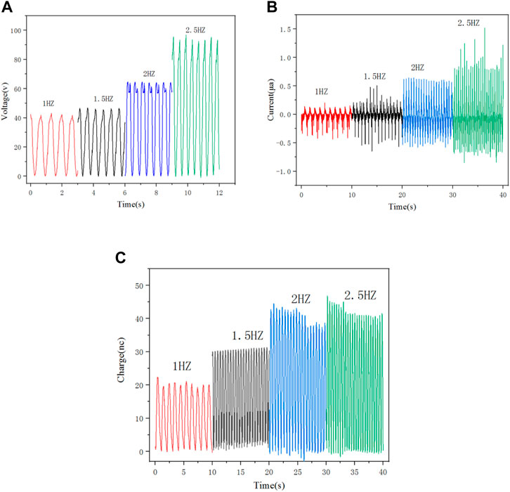
FIGURE 9. Output performance at the same amplitude and different frequencies. (A) Open-circuit voltage; (B) Short-circuit current; (C) Transfer of charge.
4.3 Effect of amplitude on TENG output performance
The effect of amplitude on THE TENG’s output performance was then investigated. Amplitude refers to the maximum distance between the inner core and the outer shell at each contact separation in a TENG device. Four values of amplitude — 30 mm, 40 mm, 50 mm and 60 mm, were selected in the present work. In analysis of the impact of amplitude on the output performance, other factors were controlled to be constant for controlled experiments. In this case, the acceleration and motion of the linear motor were controlled, and the frequency was adjusted to the same value for each test on the four different amplitudes. Specifically, the frequency was set at 2 Hz, and 0.3-mm-thick PTFE was used as the dielectric film.
Figure 10 shows the experiment result. At the four amplitudes, the maximum open-circuit voltage is 50 V, 60 V, 70 V and 110 V, respectively; the maximum short circuit current is 0.3, 0.75, 1.1 and 1.5 µA, respectively; and the maximum transferred charge is 21 nC, 30 nC, 45 nC, and 54 nC, respectively. The open-circuit voltage, short-circuit current and transferred charge all increase significantly as the amplitude rises. Here, at a constant frequency, the increase in amplitude is accompanied by an increase in the speed of motion of the TENG device, so both the open-circuit voltage and the transferred charge increase. As the speed of movement increases, the wool adhering to the PTFE film comes into closer frictional contact with the aluminum foil, which also increases the electrical output after horizontal sliding.
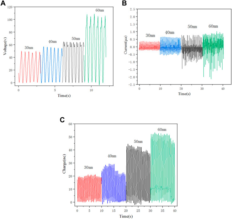
FIGURE 10. Output performance at the same frequency and different amplitudes. (A) Open-circuit voltage; (B) Short-circuit current; (C) Transfer of charge.
4.4 Durability of TENG
The durability of the TENG was tested and Figure 11 shows the test result. The linear motor parameters were set, with the frequency set to 2.5 Hz and the amplitude to 50 mm. The wool friction layer TENG’s open-circuit voltage started out at about 100 V, as indicated in Figure 11. The open-circuit voltage dropped to 95 with only a small 5% decline after 1,500 rounds of durability testing. After 1,500 cycles of durability testing, the friction layer without wool as an additional material had an open circuit voltage of 76 and a 24% drop in voltage. This suggests that the wool friction layer is more stable over time, which is good for vibration energy gathering.
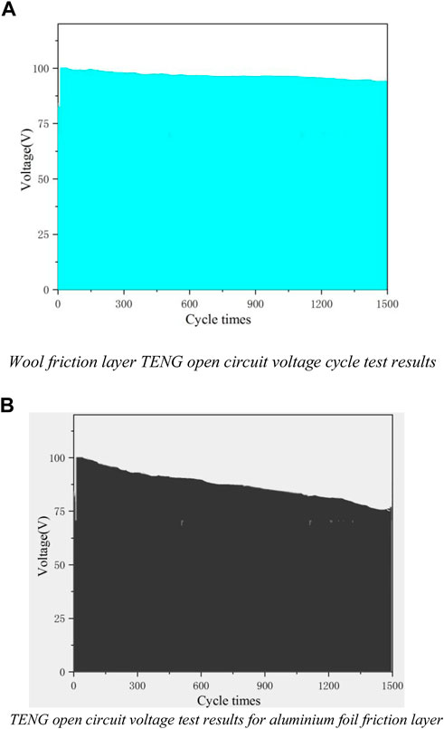
FIGURE 11. TENG durability test results. (A) Wool friction layer TENG open circuit voltage cycle test results. (B) TENG open circuit voltage test results for aluminium foil friction layer.
5 Conclusion
In the present work, a soft-contact triboelectric nanogenerator (TENG) for capturing vibrational energy is designed, and its output performance is examined using the concepts of friction-generated electricity and electrostatic induction. The COMSOL software is used to simulate the horizontal sliding TENG. A brief description of the simulation procedure is given, and the findings are theoretically examined. The effect of wool as the supplementary material on the TENG’s performance is then investigated. The findings indicate that using a friction layer with wool improves output performance and mechanical durability compared to using a friction layer without wool. Then, the effect of the frequency on the TENG’s performance is examined, and it is found that the performance improves linearly with the increasing frequency. The higher the frequency, the higher the open circuit voltage, short circuit current and peak transfer charge will be. Experiments that measure the impact of vibration amplitude on the TENG’s performance reveal that increased amplitude leads to better performance. The higher the amplitude, the higher the open circuit voltage, short circuit current and peak transfer charge will be. Durability tests indicate that the soft-contact TENG with wool adhesives is found to be exceptionally durable, boasting decreased mechanical wear on the contact surfaces and extended service life. These findings are expected to offer some insights into the working mechanism of TENGs and widen the adoption of low-loss and high-performance TENGs.
Data availability statement
The original contributions presented in the study are included in the article/Supplementary Material, further inquiries can be directed to the corresponding author.
Author contributions
JY proposed the conception, wrote, and edited the manuscript. NM drafted the manuscript and figures. DZ participated in drafting and editing the manuscript as well as checking references. YZ performed electrical performance simulations. All authors listed in the paper have made a substantial, direct, and intellectual contribution to the work and approved of its publication.
Funding
The authors gratefully acknowledge the support from National Nature Science Foundation of China (51979045), Natural Science Foundation of Guangdong Province (2022A1515011562) and Guangdong Provincial Special Fund for promoting high quality economic development [GDNRC (2021)56, Yuerong Office Letter (2020)161].
Conflict of interest
The authors declare that the research was conducted in the absence of any commercial or financial relationships that could be construed as a potential conflict of interest.
Publisher’s note
All claims expressed in this article are solely those of the authors and do not necessarily represent those of their affiliated organizations, or those of the publisher, the editors and the reviewers. Any product that may be evaluated in this article, or claim that may be made by its manufacturer, is not guaranteed or endorsed by the publisher.
References
Bera, B. (2016). Literature review on triboelectric nanogenerator[J]. Imperial J. Interdiscip. Res. (IJIR) 2 (10), 1263–1271.
Cao, X., Jie, Y., Wang, N., and Wang, Z. L. (2016). Triboelectric nanogenerators driven self-powered electrochemical processes for energy and environmental science. Adv. Energy Mat. 6 (23), 1600665. doi:10.1002/aenm.201600665
Chen, A., Zhang, C., Zhu, G., and Wang, Z. L. (2020). Polymer materials for high‐performance triboelectric nanogenerators. Adv. Sci. (Weinh). 7 (14), 2000186. doi:10.1002/advs.202000186
Chen, J., and Wang, Z. L. (2017). Reviving vibration energy harvesting and self-powered sensing by a triboelectric nanogenerator. Joule 1 (3), 480–521. doi:10.1016/j.joule.2017.09.004
Chen, J., Yang, J., Guo, H., Li, Z., Zheng, L., Su, Y., et al. (2015). Automatic mode transition enabled robust triboelectric nanogenerators. ACS Nano 9 (12), 12334–12343. doi:10.1021/acsnano.5b05618
Cheng, T., Gao, Q., and Wang, Z. L. (2019). The current development and future outlook of triboelectric nanogenerators: A survey of literature. Adv. Mat. Technol. 4 (3), 1800588. doi:10.1002/admt.201800588
Feng, P. Y., Xia, Z., Sun, B., Jing, X., Li, H., Tao, X., et al. (2021). Enhancing the performance of fabric-based triboelectric nanogenerators by structural and chemical modification. ACS Appl. Mat. Interfaces 13 (14), 16916–16927. doi:10.1021/acsami.1c02815
Guo, Hengyu, Zi, Yunlong, Wen, Zhen, Chen, J., Liu, G., Hu, C., et al. (2017). Ultralight cut-paper-based self-charging power unit for self-powered portable electronic and medical systems. ACS Nano 11 (5), 4475–4482. doi:10.1021/acsnano.7b00866
Jang, S., Joung, Y., Kim, H., Cho, S., Ra, Y., Kim, M., et al. (2022). Charge transfer accelerating strategy for improving sensitivity of droplet based triboelectric sensors via heterogeneous wettability. Nano Energy 97, 107213. doi:10.1016/j.nanoen.2022.107213
Jang, S., La, M., Cho, S., Yun, Y., Choi, J. H., Ra, Y., et al. (2020). Monocharged electret based liquid-solid interacting triboelectric nanogenerator for its boosted electrical output performance. Nano Energy 70, 104541. doi:10.1016/j.nanoen.2020.104541
Jing, Qingshen, Zhu, Guang, Bai, Peng, Xie, Y., Chen, J., Han, R. P. S., et al. (2014). Case-encapsulated triboelectric nanogenerator for harvesting energy from reciprocating sliding motion. Acs Nano 8 (4), 3836–3842. doi:10.1021/nn500694y
Khandelwal, G., Raj, N. P. M. J., and Kim, S. J. (2020). Triboelectric nanogenerator for healthcare and biomedical applications. Nano Today 33, 100882. doi:10.1016/j.nantod.2020.100882
Li, H., Deng, J., Feng, P., Pu, C., Arachchige, D. D. K., and Cheng, Q. (2021). Short-term nacelle orientation forecasting using bilinear transformation and ICEEMDAN framework. Front. Energy Res. 9, 780928. doi:10.3389/fenrg.2021.780928
Li, H., Deng, J., Yuan, S., Feng, P., and Arachchige, D. D. K. (2021). Monitoring and identifying wind turbine generator bearing faults using deep belief network and EWMA control charts. Front. Energy Res. 9, 799039. doi:10.3389/fenrg.2021.799039
Li, H. (2022). SCADA data based wind power interval prediction using LUBE-based deep residual networks. Front. Energy Res. 10, 920837. doi:10.3389/fenrg.2022.920837
Li, H. (2022). Short-term wind power prediction via spatial temporal analysis and deep residual networks. Front. Energy Res. 10, 920407. doi:10.3389/fenrg.2022.920407
Li, Q., Liu, W., Yang, H., He, W., Long, L., Wu, M., et al. (2021). Ultra-stability high-voltage triboelectric nanogenerator designed by ternary dielectric triboelectrification with partial soft-contact and non-contact mode. Nano Energy 90, 106585. doi:10.1016/j.nanoen.2021.106585
Liang, Xi, Jiang, Tao, Liu, Guoxu, Feng, Y., Zhang, C., and Wang, Z. L. (2020). Spherical triboelectric nanogenerator integrated with power management module for harvesting multidirectional water wave energy. Energy Environ. Sci. 13 (1), 277–285. doi:10.1039/c9ee03258d
Lin, Z., Chen, J., and Yang, J. (2016). Recent progress in triboelectric nanogenerators as a renewable and sustainable power source. J. Nanomater. 2016, 1–24. doi:10.1155/2016/5651613
Lin, Z., Zhang, B., Zou, H., Wu, Z., Guo, H., Zhang, Y., et al. (2020). Rationally designed rotation triboelectric nanogenerators with much extended lifetime and durability. Nano Energy 68, 104378. doi:10.1016/j.nanoen.2019.104378
Liu, S., Li, X., Wang, Y., Yang, Y., Meng, L., Cheng, T., et al. (2021). Magnetic switch structured triboelectric nanogenerator for continuous and regular harvesting of wind energy. Nano Energy 83, 105851. doi:10.1016/j.nanoen.2021.105851
Liu, W., Wang, Z., and Hu, C. (2021). Advanced designs for output improvement of triboelectric nanogenerator system. Mater. Today 45, 93–119. doi:10.1016/j.mattod.2020.11.012
Liu, Y., Ping, J., and Ying, Y. (2021). Recent progress in 2D‐nanomaterial‐based triboelectric nanogenerators. Adv. Funct. Mat. 31 (17), 2009994. doi:10.1002/adfm.202009994
Long, L., Liu, W., Wang, Z., Wencong, H., Gui, L., Qian, T., et al. (2021). High performance floating self-excited sliding triboelectric nanogenerator for micro mechanical energy harvesting[J]. Nat. Commun. 12 (1), 1–10.
Niu, S., Liu, Y., Wang, S., Lin, L., Zhou, Y. S., Hu, Y., et al. (2014). Theoretical investigation and structural optimization of single-electrode triboelectric nanogenerators. Adv. Funct. Mat. 24 (22), 3332–3340. doi:10.1002/adfm.201303799
Nurmakanov, Y., Kalimuldina, G., Nauryzbayev, G., Adair, D., and Bakenov, Z. (2021). Structural and chemical modifications towards high-performance of triboelectric nanogenerators. Nanoscale Res. Lett. 16 (1), 122–127. doi:10.1186/s11671-021-03578-z
Qin, H., Cheng, G., Zi, Y., Gu, G., Zhang, B., Shang, W., et al. (2018). High energy storage efficiency triboelectric nanogenerators with unidirectional switches and passive power management circuits. Adv. Funct. Mat. 28 (51), 1805216. doi:10.1002/adfm.201805216
Quan, T., Wu, Y., and Yang, Y. (2015). Hybrid electromagnetic–triboelectric nanogenerator for harvesting vibration energy. Nano Res. 8 (10), 3272–3280. doi:10.1007/s12274-015-0827-6
Rodrigues, C., Nunes, D., Clemente, D., Mathias, N., Correia, J. M., Rosa-Santos, P., et al. (2020). Emerging triboelectric nanogenerators for ocean wave energy harvesting: State of the art and future perspectives. Energy Environ. Sci. 13 (9), 2657–2683. doi:10.1039/d0ee01258k
Wang, S., Lin, L., and Wang, Z. L. (2015). Triboelectric nanogenerators as self-powered active sensors. Nano Energy 11, 436–462. doi:10.1016/j.nanoen.2014.10.034
Wang, Xiaofeng, Niu, Simiao, Yin, Yajiang, Hao, C., Zhang, Y., et al. (2017). Harvesting ambient vibration energy over a wide frequency range for self-powered electronics. ACS Nano 11 (2), 1728–1735. doi:10.1021/acsnano.6b07633
Wang, Z. L. (2021). From contact electrification to triboelectric nanogenerators. Rep. Prog. Phys. 84 (9), 096502. doi:10.1088/1361-6633/ac0a50
Wu, C., Liu, R., Wang, J., Zi, Y., Lin, L., and Wang, Z. L. (2017). A spring-based resonance coupling for hugely enhancing the performance of triboelectric nanogenerators for harvesting low-frequency vibration energy. Nano Energy 32, 287–293. doi:10.1016/j.nanoen.2016.12.061
Wu, Yesheng, Qi, Liu, Cao, Jie, Li, K., Cheng, G. G., Zhang, Z. Q., et al. (2019). Design and output performance of vibration energy harvesting triboelectric nanogenerator. Acta Phys. Sin. 68 (19), 190201. doi:10.7498/aps.68.20190806
Xia, K., Zhu, Z., Zhang, H., Du, C., Fu, J., and Xu, Z. (2019). Milk-based triboelectric nanogenerator on paper for harvesting energy from human body motion. Nano Energy 56, 400–410. doi:10.1016/j.nanoen.2018.11.071
Xia, K., Zhu, Z., Zhang, H., Du, C., Xu, Z., and Wang, R. (2018). Painting a high-output triboelectric nanogenerator on paper for harvesting energy from human body motion. Nano Energy 50, 571–580. doi:10.1016/j.nanoen.2018.06.019
Xia, Kequan, Fu, Jiangming, and Xu, Zhiwei (2020). Multiple‐frequency high‐output triboelectric nanogenerator based on a water balloon for all‐weather water wave energy harvesting. Adv. Energy Mat. 10 (28), 2000426. doi:10.1002/aenm.202000426
Xu, Liang, Jiang, Tao, Shao, Jiajia, He, C., Zhong, W., Chen, X. Y., et al. (2018). Coupled triboelectric nanogenerator networks for efficient water wave energy harvesting. ACS Nano 12 (2), 1849–1858. doi:10.1021/acsnano.7b08674
Yang, W., Chen, J., Zhu, G., Wen, X., Bai, P., Su, Y., et al. (2013). Harvesting vibration energy by a triple-cantilever based triboelectric nanogenerator. Nano Res. 6 (12), 880–886. doi:10.1007/s12274-013-0364-0
Yang, Weiqing, Chen, Jun, Wang, Zhonglin, Jing, Q., Yang, J., Su, Y., et al. (2014). Triboelectrification based motion sensor for human-machine interfacing. ACS Appl. Mat. Interfaces 6 (10), 7479–7484. doi:10.1021/am500864t
Yoo, D., Kim, S. J., Joung, Y., Jang, S., and Choi, D. (2022). Lotus leaf-inspired droplet-based electricity generator with low-adhesive superhydrophobicity for a wide operational droplet volume range and boosted electricity output. Nano Energy 99, 107361. doi:10.1016/j.nanoen.2022.107361
Yu, Aifang, Jiang, Peng, Wang, Zhonglin, et al. (2012). Nanogenerator as self-powered vibration sensor[J]. Nano Energy 1 (3), 418–423.
Yun, Y., La, M., Cho, S., Jang, S., Choi, J. H., Ra, Y., et al. (2021). High quality electret based triboelectric nanogenerator for boosted and reliable electrical output performance. Int. J. Precis. Eng. Manuf. -Green. Tech. 8 (1), 125–137. doi:10.1007/s40684-020-00245-z
Zhang, Nan, Cheng, Qin, Jun, Li, Yang, Z., Sun, X., Liang, E., et al. (2020). Non-contact cylindrical rotating triboelectric nanogenerator for harvesting kinetic energy from hydraulics. Nano Res. 13 (7), 1903–1907. doi:10.1007/s12274-020-2654-7
Zhang, Q., Zhang, Z., Liang, Q., Gao, F., Yi, F., Ma, M., et al. (2019). Green hybrid power system based on triboelectric nanogenerator for wearable/portable electronics. Nano Energy 55, 151–163. doi:10.1016/j.nanoen.2018.10.078
Zhang, R., Hummelgård, M., Örtegren, J., Olsen, M., Andersson, H., and Olin, H. (2019). Interaction of the human body with triboelectric nanogenerators. Nano Energy 57, 279–292. doi:10.1016/j.nanoen.2018.12.059
Zhao, Hongfa, Xiao, Xiu, Xu, Peng, Zhao, T., Song, L., Pan, X., et al. (2019). Dual‐tube helmholtz resonator‐based triboelectric nanogenerator for highly efficient harvesting of acoustic energy. Adv. Energy Mat. 9 (46), 1902824. doi:10.1002/aenm.201902824
Zheng, Q., Shi, B., Li, Z., and Wang, Z. L. (2017). Recent progress on piezoelectric and triboelectric energy harvesters in biomedical systems. Adv. Sci. (Weinh). 4 (7), 1700029. doi:10.1002/advs.201700029
Zheng, Y., Liu, T., Wu, J., Xu, T., Wang, X., Han, X., et al. (2022). Energy conversion analysis of multilayered triboelectric nanogenerators for synergistic rain and solar energy harvesting. Adv. Mater. 34, 2202238. doi:10.1002/adma.202202238
Keywords: TENG, wool, horizontal sliding, improved durability, vibration energy
Citation: Yan J, Mei N, Zhang D and Zhong Y (2022) Design of a soft-contact triboelectric nanogenerator for vibrational energy collection and its output performance. Front. Energy Res. 10:1014983. doi: 10.3389/fenrg.2022.1014983
Received: 09 August 2022; Accepted: 14 September 2022;
Published: 27 September 2022.
Edited by:
Yusen He, The University of Iowa, United StatesReviewed by:
Dongwhi Choi, Kyung Hee University, South KoreaXiang Zhu, Huazhong University of Science and Technology, China
Jingxi Liu, Huazhong University of Science and Technology, China
Copyright © 2022 Yan, Mei, Zhang and Zhong. This is an open-access article distributed under the terms of the Creative Commons Attribution License (CC BY). The use, distribution or reproduction in other forums is permitted, provided the original author(s) and the copyright owner(s) are credited and that the original publication in this journal is cited, in accordance with accepted academic practice. No use, distribution or reproduction is permitted which does not comply with these terms.
*Correspondence: Dapeng Zhang, zhangdapeng@gdou.edu.cn