Experimental Study on Sweep Characteristics of Gas Gravity Drainage in the Interlayer Oil Reservoir
 Hongwei Yu
 Lu Wang
 Daiyu Zhou3
  Fuyong Wang
- 1State Key Laboratory of Enhanced Oil Recovery, PetroChina Research Institute of Petroleum Exploration and Development, Beijing, China
- 2Unconventional Petroleum Research Institute, China University of Petroleum, Beijing, China
- 3Research Institute of Petroleum Exploration and Development, Tarim Oilfield, Korla, China
Stable gas gravity drainage is considered an effective method to enhance oil recovery, especially suitable for deep buried, large dip angle, and thick oil reservoirs. The influence of reservoir heterogeneity on controlling the gas–oil interface and sweep characteristics of injected gas is particularly important to design reservoir development schemes. In this study, according to the interlayer characteristics of Donghe carboniferous oil reservoirs in the Tarim Basin, NW China, 2D visual physical models are established, in which the matrix permeability is 68.1 mD and average pore throat radius is 60 nm. Then, hydrocarbon gas gravity drainage simulation experiments are carried out systematically, and a high-speed camera is used to record the process of gas–oil flow and interface movement. In this experiment, the miscible zone of crude oil and hydrocarbon gas is observed for the first time. The interlayer has an obvious shielding influence, which can destroy the stability of the gas–oil interface and miscible zone, change the movement direction of the gas–oil interface, and reduce the final oil recovery after gravity drainage. The remaining oil mainly is distributed near the interlayers. The higher displacement pressure leads to increased stability of the gas–oil displacement front and later gas breakthrough, which leads to higher oil recovery. The lower gas injection rate contributes to a slower front velocity and wider miscible zone, which could delay gas breakthrough. For the immiscible gas gravity drainage, there is a critical gas injection rate, with which the oil recovery factor is the highest.
Introduction
Low-permeability reservoirs account for about 46% of oil and gas resources in China (HU et al., 2018). Due to the poor physical properties, fracture development, and strong heterogeneity, the water flooding efficiency in low-permeability oil reservoirs is low. Therefore, it is crucial to exploit the remaining oil of low-permeability oil reservoirs with advanced technologies.
Several studies have shown that the oil recovery factor of low-permeability sandstone reservoirs can be improved by gas injection after water flooding (Liu, 2012). Gas injection flooding mainly includes nitrogen flooding, air flooding, hydrocarbon gas flooding, and CO2 flooding (Feng et al., 2019). Janssen et al. (2018) analyzed several immiscible nitrogen injection schemes and found that compared with the two-phase flow, the residual oil saturation after immiscible nitrogen flooding was lower. Yang et al. (2020) conducted four kinds of nitrogen flooding experiments on typical fractured-vuggy carbonate reservoirs using 2D visual models and reported that the recovery rate of nitrogen flooding is 12% lower than that of foam-assisted nitrogen flooding, which is mainly because of foam delaying gas channeling. Jiang et al. (2010) studied the mechanism of air flooding in low-permeability oil reservoirs by combining numerical simulation with physical simulation and demonstrated that air injection is useful for establishing an effective pressure displacement system. Lai et al. (2014) studied the phase change and the characteristics of dynamic oil displacement efficiency in the process of gas injection based on the slim-tube test and pointed out that the main mechanism of hydrocarbon gas flooding was evaporation and condensation. CO2 miscible flooding is to improve the volumetric sweep efficiency by reducing the viscosity and density of crude oil and ultimately achieve the purpose of improving oil recovery (Behnoudfar, 2018). In addition, CO2 can also improve CBM recovery by occupying the original adsorption position of CH4 in coal (Liu et al., 2019).
In recent years, gas gravity drainage technology has been widely used worldwide. Its main technical characteristics are as follows: gas injection at the top of the reservoir, promotion of the stability of gas–oil interface by the gas overlap, expansion of the swept volume, and exploitation of the lower part remaining oil. Ren et al. (2018) analyzed the influencing factors of steady gas gravity drainage and found that the reduction of the crude oil viscosity and gas injection rate and the increase of formation inclination can extend the time of steady gravity drainage and increase the oil recovery factor. Parsaei and Chatzis (2011) studied the influence of wettability heterogeneity on the gravity-assisted inert gas injection (GAIGI) process and pointed out that the GAIGI process was more effective than water injection as it can reduce the residual oil saturation in heterogeneous porous media. Fan et al. (2015) explored the sealing characteristics of the interlayers during gas injection and found that the continuous interlayer has a strong sealing capacity, but the sealing capacity of the discontinuous interlayer is related to its distribution range.
In this paper, the physical models for physically simulating gas gravity drainage are established to investigate the effects of the distribution of interlayers and fractures on oil production by miscible and immiscible hydrocarbon/nitrogen gravity drainage. The gas–oil front and miscible zone are observed in the physical models. The key factors influencing sweep characteristics of gas gravity drainage performance, such as distributions of interlayers and fractures, gas injection rate, and pressure, are studied.
Geological Background
The Tarim Basin is the largest oil-containing basin in China, which covers an area of 560,000 square kilometers (Fang et al., 2018). The block of this study is the Donghe 1CIII reservoir in the Tarim Basin, which is a thick sandstone oil reservoir. The top structure of this reservoir is an asymmetric short-axis anticline, the long-axis direction is northeast–southwest, and the ratio of the long axis to the short axis is 2.7. The lengths of the long axis and short axis are 5.1 and 1.9 km, respectively. The top of the reservoir is flat, and the corresponding dip angle is between 3° and 4°. The northwest wing angle is 12°, which is steep. In contrast, the southeast wing is relatively flat with an inclination of 4.5° (Ye, 2019). The average porosity is 15.1%, the average permeability is 68.1 × 10⁻³ μm2, and the average pore throat radius is 60 nm. The interlayers in this area are widely distributed.
Design and Preparation of 2D Visual Model
Model Design
To reveal the sweep characteristics of stable gas gravity drainage in typical oil reservoirs, seven 2D visual large rock models are designed according to physical properties and interlayer distributions in Donghe 1CIII, Tarim Basin, and the lower Wuerhe oil reservoir in block 8 of the Xinjiang Oilfield, the sweep characteristics of gas gravity drainage can be observed with these models, and the detailed parameters of these models are shown in Table 1. The model size is 150 × 170 × 20 mm, and there are two to three compartments and two to four fractures in the models.
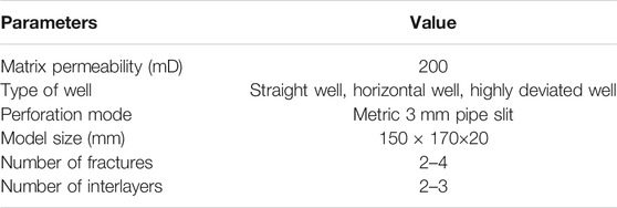
TABLE 1. Design parameters of the 2D visual model.
There are two different types of 2D visual models, i.e., interlayer models and vertical fracture models. According to the location of the interlayer, injection well, perforation location, and production well, the interlayer model can be divided into five different types, as shown in Figure 1. It can be found that the interlayer is between the injection well and the horizontal production well, while the vertical production well and the highly deviated production well pass through the interlayer. Although the first, second, and third types of models have the characteristics of the dual interlayer, there are certain differences. Compared with the third model, the second model has one more horizontal production well between the two interlayers. In the first model, two more vertical production wells were drilled based on the second model, and the injection wells were located above the right of the model. Similarly, the vertical fracture model can be subdivided into two types, as shown in Figure 2. The production wells are horizontal and perforated in the horizontal section in the first type model. In the second type model, there are two vertical production wells and two vertical injection wells.

FIGURE 1. Design diagram of interlayer models.
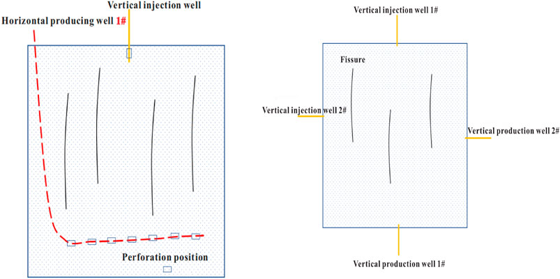
FIGURE 2. Design diagram of vertical fracture models.
To sum up, we can combine the interlayer model and vertical fracture model to change the injection and production modes through the change of location and combination of the vertical wells, horizontal wells, highly deviated wells, and the perforation position, to achieve different experimental purposes.
Model Preparation
As shown in Figure 3, four 2D visual large rock models including the homogeneous model, dual interlayer heterogeneous model, triple interlayer heterogeneous model, and dual vertical fracture heterogeneous model are prepared. Taking the homogeneous model as the control group, the influence of the interlayers and vertical fractures on the sweep characteristics of gas gravity drainage was obtained by comparing the experimental results of the homogeneous model and the other three heterogeneous models.
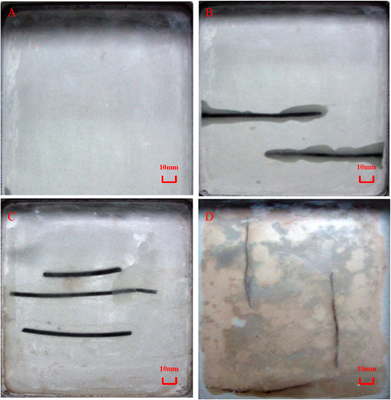
FIGURE 3. Two-dimensional visualization of large rock models: (A) homogeneous model; (B) dual interlayer heterogeneous model; (C) triple interlayer heterogeneous model; (D) dual vertical fracture heterogeneous model.
Experimental Materials and Methods
Experimental Materials
The oil samples used in the experiments are made up of kerosene, dead oil from the oilfield, and n-pentane, and the viscosity of the oil is 4.09 mPa·s under the reservoir condition (140°C and 45 MPa). Propane with 99.95% purity and nitrogen with 99.99% purity are used as the injected gases.
Experimental Equipment
As shown in Figure 4, the experimental equipment mainly includes three parts: injection system, measurement system, and 2D visual model. Among them, the ISCO pump, distilled water, gas intermediate vessel, and simulated oil intermediate vessel compose the injection system. The metering system includes three parts: back-pressure regulator, output liquid metering device, and gas flow meter. The 2D visual model system contains a camera that is used to monitor the process of gas drainage at different times.
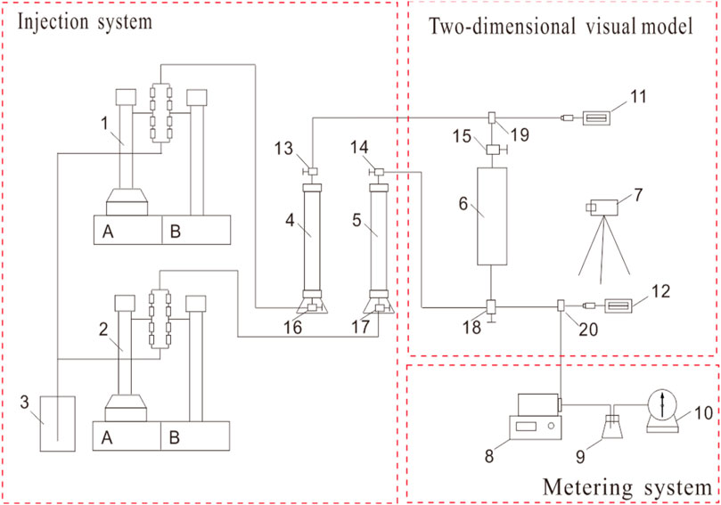
FIGURE 4. 2D visual flow chart of the hydrocarbon gas gravity drainage sweep characteristic experiment (1, 2: ISCO pump; 3: distilled water; 4: gas intermediate container; 5: oil intermediate container; 6: interlayer model; 7: camera; 8: back-pressure regulator; 9: output liquid metering device; 10: gas flow meter; 11, 12: digital pressure gauge; 13, 14, 15, 16, 17, 18: stop valve; 19, 20: three-way valve).
Experimental Procedures
1) The model was vacuumized for more than 12 h.
2) The model was saturated with the simulated oil from the bottom, and the volume of the injected oil was more than three times the pore volume of the model.
3) The gas was injected from the top of the model with the constant rate, and the oil was produced at the bottom. The image of gas drainage during the experiments was taken by a camera every 10–60 s, and the time interval was set according to the injection and production rates. Meanwhile, the produced oil and gas volume was measured with a certain interval. The experiment ended when no more oil was produced.
4) The model was cleaned with the organic solvent, and the injection volume was more than five times the pore volume of the model.
Experimental Results and Discussion
Immiscible Nitrogen Gravity Drainage
The characteristics of immiscible gravity drainage include that the vertical movement of the gas–oil interface can be automatically adjusted, and the macroscopic sweep coefficient is high, but the microscopic oil displacement efficiency is low due to the unstable displacement process. However, in practice, the sweep characteristics of gas drainage and remaining oil distribution are affected by interlayers and fractures in oil reservoirs. Therefore, to reveal the influence of barriers, interlayers, and fractures on the sweep characteristics of immiscible nitrogen gravity drainage, the homogeneous model and the double vertical fracture model were used in the experiment.
The immiscible nitrogen gravity drainage in the homogeneous model is shown in Figure 5. At the initial stage of gas displacement, as shown in Figures 5A–C, the change of crude oil in the model is not obvious. After that, the morphology of the displacement front can be observed. Then, the displacement front did not advance steadily but rushed down along the model boundary, and the uneven and unstable gas–oil interface appeared. The gas–oil interface is conveyed in Figures 5D–G.
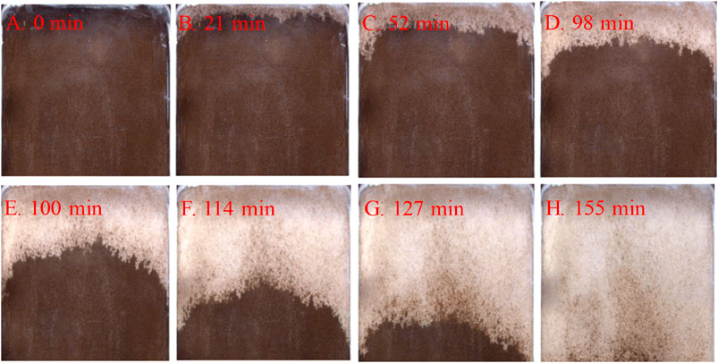
FIGURE 5. Gas–oil front of immiscible nitrogen gravity drainage vs. time in the homogenous model: (A) 0 min; (B) 21 min; (C) 52 min; (D) 98 min; (E) 100 min; (F) 114 min; (G) 127 min; (H) 155 min.
Figure 5H is the photo of the end of immiscible nitrogen gravity drainage, and it can be found that the microscopic oil displacement efficiency of immiscible nitrogen gravity drainage in the homogeneous model is relatively low, and there is a lot of remaining oil in the pores, which is mainly distributed in the middle and lower parts of the model.
Figure 6 illustrates the immiscible nitrogen flooding with a high injection rate in the dual vertical fracture heterogeneous model. The sweep characteristics of immiscible nitrogen flooding can be summarized as follows:
1) In the early stage of displacement, the advance speed of the displacement front is slow.
2) In immiscible nitrogen gravity drainage, the oil displacement efficiency is low, and only small-scale local gas channeling occurs near fractures.
3) The gas–oil interface is less affected by the fluctuation of injection velocity, and the movement of the front is relatively stable.
4) A large amount of the remaining oil is distributed in the lower part of the model.
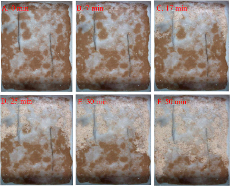
FIGURE 6. Gas–oil front of immiscible nitrogen gravity drainage vs. time in the dual vertical fracture model with high gas injection rates: (A) 0 min; (B) 7 min; (C) 17 min; (D) 25 min; (E) 30 min; (F) 50 min.
In addition, the effects of different gas injection rates on oil recovery were analyzed in this dual vertical fracture model, as shown in Figure 7. It is found that when the gas injection rate increases from 0.01 to 2 cm3/min, the oil recovery factor decreases from 71.22 to 66.86%, which means that the increasing gas injection rate leads to the reduction of oil recovery, but the reduction is insignificant.
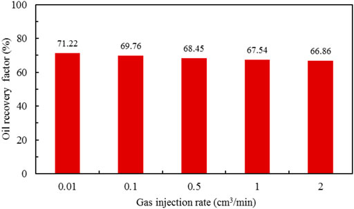
FIGURE 7. Oil recovery factor of immiscible nitrogen gravity drainage with different injection rates in the dual vertical fracture heterogeneous model.
Immiscible Hydrocarbon Gas Gravity Drainage
As shown in Figure 8, a homogeneous model was used to study the immiscible hydrocarbon gas gravity drainage mechanism. It can be seen that the sweep characteristics of immiscible hydrocarbon gas gravity drainage are different from those of immiscible nitrogen gravity drainage. The sweep characteristics of immiscible hydrocarbon gravity drainage are summarized as follows:
1) In the early stage of displacement, there is an obvious semicircular gas front, and then the injected gas slowly forms a gas cap and displaces evenly with the progress of gas displacement.
2) The displacement front becomes more stable, and the injected gas displaces down along the model boundary as a result of the relatively small resistance.
3) The gas–oil interface is relatively uniform and stable.
4) The microscopic oil displacement efficiency is relatively good. It can be seen from the photos that the remaining oil in the pores is small and mainly distributed in the middle and lower parts of the model.
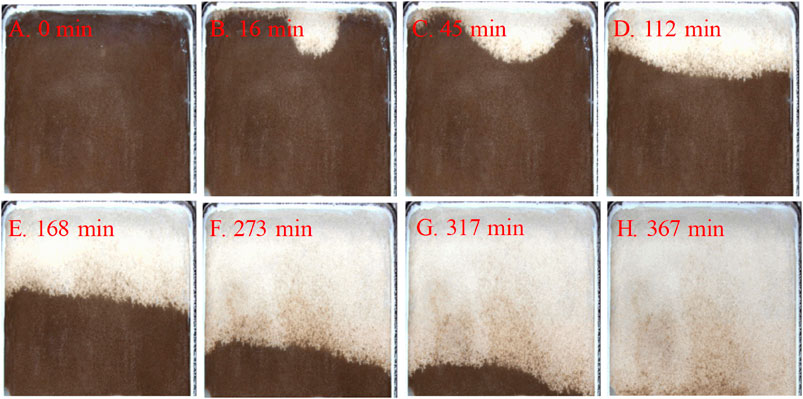
FIGURE 8. Gas–oil front during immiscible hydrocarbon gas gravity drainage vs. time in the homogeneous model: (A) 0 min; (B) 16 min; (C) 45 min; (D) 112 min; (E) 168 min; (F) 273 min; (G) 317 min; (H) 367 min.
Miscible Hydrocarbon Gas Gravity Drainage
The miscible zone with the disappearance of the gas–oil interface can be observed in immiscible hydrocarbon gas gravity drainage. Compared with the immiscible hydrocarbon gas gravity drainage, the miscible hydrocarbon gravity drainage has a more stable displacement front, higher sweep volume, and higher displacement efficiency. The prerequisite for effective miscible gravity drainage is that the minimum miscible pressure should be no more than the reservoir pressure (Wei et al., 2019). The minimum miscible pressure can be determined by five different methods: rising bubble method, slim-tube method, core displacement experiment, interfacial tension measurement, and pressure–volume–temperature experiment (Zhang et al., 2019).
Three different models including the homogeneous model, the dual interlayer model, and the fracture model are selected for miscible hydrocarbon gravity drainage. The process of miscible hydrocarbon gas gravity drainage in the homogeneous model is shown in Figure 9. Similar to immiscible hydrocarbon gravity drainage, the injected gas firstly plunged and then formed a gas cap. The gas–oil interface is uniform and stable. The displacement front is stable without breakthrough along the model boundary. Overall, the microscopic oil displacement efficiency of miscible hydrocarbon gas gravity drainage is the best, as the remaining oil in pores is minimum.
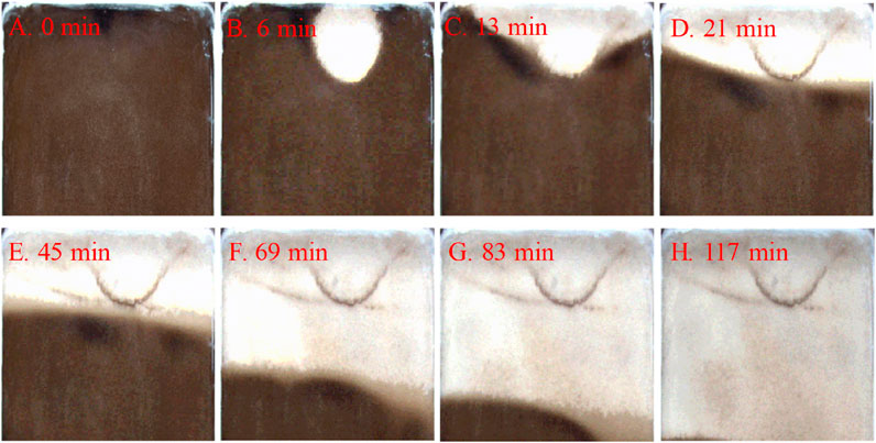
FIGURE 9. Hydrocarbon gas miscible gravity drainage in the homogeneous model at different times: (A) 0 min; (B) 6 min; (C) 13 min; (D) 21 min; (E) 45 min; (F) 69 min; (G) 83 min; (H) 117 min.
Before the experiment of miscible hydrocarbon gas gravity drainage in the dual interlayer model, it is necessary to saturate the model with the oil. The oil saturation process is shown in Figure 10. The oil was injected from the lower right corner of the model and was produced from the middle of the model top. The injected oil volume was at least twice the total pore volume, which was 153 cm3.

FIGURE 10. Process of oil saturation in the dual interlayer model.
The hydrocarbon was injected from the middle of the model top position, and oil was produced from the bottom horizontal well. As shown in Figure 11, in the early stage of displacement, the injected gas plunged quickly and formed a gas cap and then uniformly pushed the gas–oil interface forward. Therefore, the displacement front is stable. With the increase of injected gas volume, the gas–oil interface was close to the interlayer. Due to the obvious shielding effect of the interlayer, the movement direction of the displacement front changed, the stability of the gas–oil interface and the miscible zone was destroyed, and a small amount of remaining oil was distributed in the upper part of the interlayer. Figure 12 shows that the oil production rate decreased rapidly from 1.925 to 1.05 cm3/min after gas breakthrough. The remaining oil was gradually produced, and the ultimate recovery factor remained high, reaching 94.16%.
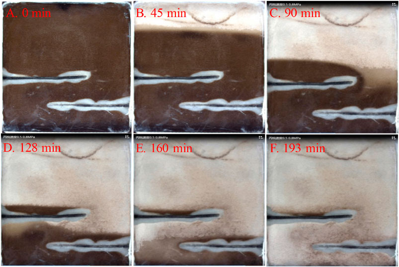
FIGURE 11. Process of miscible hydrocarbon gravity drainage in the dual interlayer heterogeneous model: (A) 0 min; (B) 45 min; (C) 90 min; (D) 128 min; (E) 160 min; (F) 193 min.
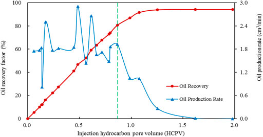
FIGURE 12. Oil recovery factor and oil production rate of miscible hydrocarbon gas flooding in the dual interlayer heterogeneous model.
The effects of different injection pressure and injection rate on the oil recovery of the miscible hydrocarbon gas gravity drainage are studied with this dual interlayer model. Figure 13 shows the effect of injected gas pressure on oil recovery. When the injected gas pressure increases from immiscible gravity drainage to miscible gravity drainage, the oil recovery increases. The reason is that the increasing displacement pressure leads to the stable gas–oil front, late gas breakthrough, and high sweep and oil displacement efficiency. In addition, comparing the oil recovery factor and gas breakthrough time of miscible drainage with low, medium, and high injection rates, it can be found that the oil recovery factor is all higher than 90% with little difference, and the high injection rate leads to the early gas breakthrough.

FIGURE 13. Oil recovery factor of gas gravity drainage with different injection pressures and rates.
Figure 14 shows the effect of gas injection rate on oil recovery. As the gas injection rate decreases, the movement of the gas–oil front will be slower and the gas breakthrough will occur later. However, after gas breakthrough, the oil production rate by gas displacement decreases. For miscible gravity drainage, the injection–production rate can be appropriately increased to enhance the capacity of carrying oil by gas. However, immiscible gravity drainage has a critical gas injection rate, with which the oil recovery factor is the highest.
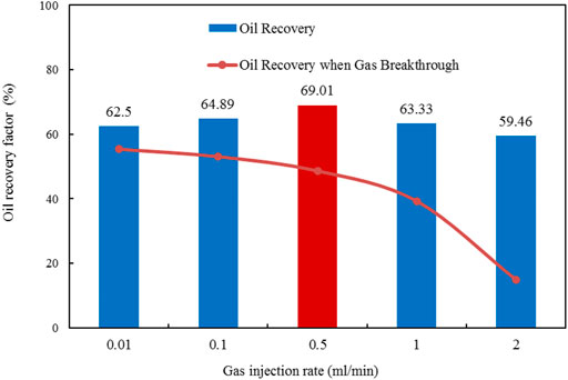
FIGURE 14. Oil recovery factor of immiscible nitrogen gravity drainage with different gas injection rates.
\The dual vertical fracture heterogeneous model was adopted to study the sweep characteristics of hydrocarbon gas gravity drainage under different pressures and injection rates. Figure 15 shows the sweep characteristics of hydrocarbon gas gravity drainage with a high gas injection rate (2 ml/min). The fractures lead to gas channeling and early gas breakthrough, which seriously destroy the stability of the gas–oil interface and miscible zone. After gas breakthrough, the oil production rate is greatly reduced, and the remaining oil is mainly distributed in the unswept area between the injection well and the production well. When the gas injection rate is reduced to 0.5 ml/min, as shown in Figure 16, the phenomenon of gas channeling becomes insignificant, the movement of the gas–oil interface becomes more stable, and the swept area of hydrocarbon gas gravity drainage increases. As shown in Figure 17, comparing the oil recovery factor of hydrocarbon gas gravity drainage with different injection rates, it can be found that when the medium gas injection rate is 0.5 ml/min, the oil recovery factor is highest. Therefore, when fractures are parallel to the gas injection direction, the gas injection rate should be optimized to obtain the highest oil recovery factor.
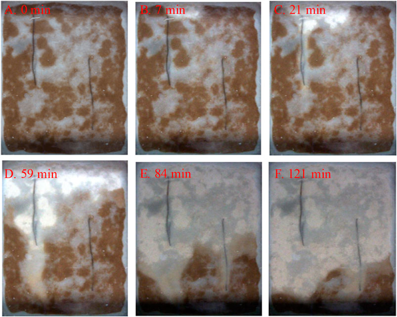
FIGURE 15. Process of miscible hydrocarbon gas flooding in a dual vertical fracture heterogeneous model with 2 ml/min gas injection rate: (A) 0 min; (B) 7 min; (C) 21 min; (D) 59 min; (E) 84 min; (F) 121 min.
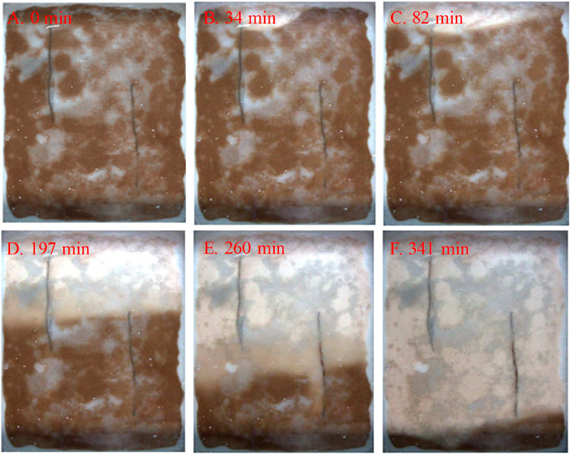
FIGURE 16. Hydrocarbon gas miscible flooding process in a dual vertical fracture heterogeneous model with 0.5 ml/min gas injection rate: (A) 0 min; (B) 34 min; (C) 82 min; (D) 197 min; (E) 260 min; (F) 341 min
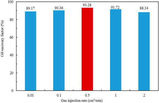
FIGURE 17. Oil recovery factor of miscible hydrocarbon gas gravity drainage in the dual vertical fracture heterogeneous model with different gas injection rates.
Methods of Enlarging Gas Sweep Volume
The experiment was carried out with a heterogeneous model with three interlayers. Firstly, miscible hydrocarbon gravity drainage was injected horizontally, and the injection production rate was controlled intermittently until no oil was produced. After that, the position of the production well was changed to enlarge the swept volume of gas gravity drainage. As shown in Figure 18, the gas injection and oil production are both parallel and horizontal. The gas firstly overlaps and then forms a gas cap. After that, oil is displaced by gas drainage and the swept area of gas gravity drainage is 55.2%. However, 44.8% of the model area cannot be swept due to the shielding effect of interlayers. Figure 19 shows that the position of the production well is changed to the bottom of the model. Gas gravity drainage continues to produce more oil, the gas–oil interface moves down evenly, and the swept area increases by 40.4%. Besides, periodic oil production through controlling the oil production rate helps form a stable gas–oil interface and enlarge macroscopic sweep efficiency.
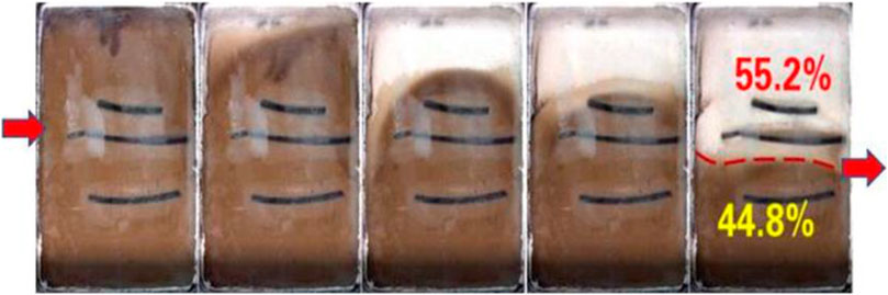
FIGURE 18. Process of gas drainage when the injection well and production well are parallel and horizontal in a heterogeneous model with three interlayers.
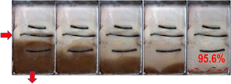
FIGURE 19. Process of gas drainage when the production well is changed to the bottom of the model.
Conclusion
The interlayers have obvious shielding effects, damage the stability of the gas–oil interface and miscible zone, and change the direction of front movement. A small amount of the remaining oil distributes in the upper part of the interlayer. The gas sweep area can be enlarged by changing the position of the production well and controlling the oil production rate.
The increase of displacement pressure leads to the stable gas–oil interface, late gas breakthrough, and high sweep and oil displacement efficiency. The oil recovery factors of miscible gravity drainage are usually higher than 90% with little difference. The high injection rate of miscible gravity drainage leads to early gas breakthroughs.
The decrease of gas injection rate leads to slow movement of gas–oil front and late gas breakthrough. The capacity of gas carrying oil is weakened after the breakthrough. For miscible gas gravity drainage, the gas injection rate can be appropriately increased to enhance the capacity of gas carrying oil. However, immiscible gas gravity drainage has a critical gas injection rate, with which the oil recovery factor of immiscible gravity drainage is the highest.
Data Availability Statement
The original contributions presented in the study are included in the article/Supplementary Material, and further inquiries can be directed to the corresponding author.
Author Contributions
HY, SL, XC, and HH conducted the experiments in the laboratory. DZ, JL, and HH provided the oilfield data and designed the experiments. LW and FW wrote the manuscript. All authors contributed to manuscript revision and read and approved the submitted version.
Funding
This work was supported by the Major Science and Technology Project of CNPC (Nos. 2019B-1111 and 2018E-1105).
Conflict of Interest
The authors declare that the research was conducted in the absence of any commercial or financial relationships that could be construed as a potential conflict of interest.
Publisher’s Note
All claims expressed in this article are solely those of the authors and do not necessarily represent those of their affiliated organizations, or those of the publisher, the editors, and the reviewers. Any product that may be evaluated in this article, or claim that may be made by its manufacturer, is not guaranteed or endorsed by the publisher.
References
Behnoudfar, P., Rostami, A., and Hemmati-Sarapardeh, A. (2018). Chapter Four - Miscible Gas Injection Processes. In Fundamentals of Enhanced Oil and Gas Recovery from Conventional and Unconventional Reservoirs. Gulf Professional Publishing, 101–138. doi:10.1016/B978-0-12-813027-8.00004-7
Fan, K., Zhu, W., Zhou, D., Gao, S., and Hu, Z. (2015). Effect of Interlayers in Thick sandstone Reservoir for Gas Injection: a Case Study of Donghe 1 Carboniferous Oil Reservoir in Tarim Basin. Acta Petrolei Sinica 36, 475–481. doi:10.7623/syxb201504008
Fang, H., Xu, H., Wang, Z., Jiang, T., Zhao, Y., and Li, J. (2018). Formation Mechanism of the Donghe Sandstone Residual Oil Zone in the Tarim Basin, NW China. J. Pet. Sci. Eng. 171, 1023–1032. doi:10.1016/j.petrol.2018.08.009
Feng, G., Hu, Y., Yao, W., Zhang, Y., and Yuan, Z. (2019). Development and Application of Gas Injection for Oil Recovery from Offshore Oilfields. J. Southwest Pet. Univ. (Science Technology Edition) 41, 147.
Hu, W., Wei, Y., and Bao, J. (2018). Development of the Theory and Technology for Low Permeability Reservoirs in China. Pet. Exploration Development 45, 685–697. doi:10.1016/S1876-3804(18)30072-7
Janssen, M. T., Azimi, F., and Zitha, P. L. (2018). Immiscible Nitrogen Flooding in Bernheimer Sandstones: Comparing Gas Injection Schemes for Enhanced Oil Recovery. In SPE Improved Oil Recovery Conference. Tulsa, Oklahoma, USA, OnePetro.
Jiang, Y., Zhang, Y., Liu, S., Guan, W., Chen, Y., and Liu, S. (2010). Displacement Mechanisms of Air Injection in Low Permeability Reservoirs. Pet. Exploration Development 37, 471–476. doi:10.1016/S1876-3804(10)60048-1
Lai, F.-p., Li, Z.-p., Yang, Z.-h., Li, H., and Guo, Z.-z. (2014). The Study of Components Mass Transfer Mechanism and the Rules of Fluid Phase Alteration in the Process of Hydrocarbon Gas Drive. J. Nat. Gas Sci. Eng. 21, 411–416. doi:10.1016/j.jngse.2014.09.008
Liu, B. (2012). Development Mechanism Study on Gas Injection in Low Permeability Sandstone Reservoir in High Water Cut Period -Taking the Example of Wenxi Block 3 Reservoir. (Beijing: China University of Geosciences).
Liu, Z., Cheng, Y., Wang, Y., Wang, L., and Li, W. (2019). Experimental Investigation of CO2 Injection into Coal Seam Reservoir at In-Situ Stress Conditions for Enhanced Coalbed Methane Recovery. Fuel 236, 709–716. doi:10.1016/j.fuel.2018.09.062
Parsaei, R., and Chatzis, I. (2011). Experimental Investigation of Production Characteristics of the Gravity-Assisted Inert Gas Injection (GAIGI) Process for Recovery of Waterflood Residual Oil: Effects of Wettability Heterogeneity. Energy Fuels 25, 2089–2099. doi:10.1021/ef200098y
Ren, S., Liu, Y., Zhang, L., Cui, G., Gong, Z., Wang, Y., et al. (2018). Gravity Assisted Gas Injection: Assessment Model and Experimental Study. J. China Univ. Pet. (Edition Nat. Science) 42, 59–66. doi:10.3969/j.issn.1673-5005.2018.04.007
Wei, C., Wang, Y., Li, B., Zhang, J., Zhang, W., and Wu, J. (2019). Miscible Gas Injection in Heterogeneous Carbonate Reservoirs with Extensive Baffles. In Abu Dhabi International Petroleum Exhibition & Conference. Manama, Bahrain, OnePetro. doi:10.2118/197345-ms
Yang, J., Hou, J., Qu, M., Liang, T., and Wen, Y. (2020). Experimental Study the Flow Behaviors and Mechanisms of Nitrogen and Foam Assisted Nitrogen Gas Flooding in 2-D Visualized Fractured-Vuggy Model. J. Pet. Sci. Eng. 194, 107501. doi:10.1016/j.petrol.2020.107501
Ye, S. (2019). Study of Gas Injection Development Method and Remaining Oil Distribution Law of W Reservoir. Beijing: China University of Petroleum.
Keywords: gravity drainage, sweep characteristics, gas flooding, interlayer, fracture
Citation: Yu H, Wang L, Zhou D, Wang F, Li S, Li J, Chen X, Cao A and Han H (2021) Experimental Study on Sweep Characteristics of Gas Gravity Drainage in the Interlayer Oil Reservoir. Front. Energy Res. 9:760315. doi: 10.3389/fenrg.2021.760315
Received: 18 August 2021; Accepted: 29 September 2021;
Published: 12 November 2021.
Edited by:
Zhixiang Zhao, Xi’an Polytechnic University, ChinaReviewed by:
Tony Gao, Variables Intelligence, United StatesYanfu Pi, Northeast Petroleum University, China
Copyright © 2021 Yu, Wang, Zhou, Wang, Li, Li, Chen, Cao and Han. This is an open-access article distributed under the terms of the Creative Commons Attribution License (CC BY). The use, distribution or reproduction in other forums is permitted, provided the original author(s) and the copyright owner(s) are credited and that the original publication in this journal is cited, in accordance with accepted academic practice. No use, distribution or reproduction is permitted which does not comply with these terms.
*Correspondence: Fuyong Wang, wangfuyong@cup.edu.cn