Effect of Rolling Deformation on Creep Properties of FeCrAl Alloys
 Huan Sheng Lai1
  Jingyu Guo1 Shanglin Zhang2
  Xiaobin Yu3
  Fanqiang Meng1 Zilong Zhao4*
  Wenzhong Zhou1*
- 1Sino-French Institute of Nuclear Engineering and Technology, Sun Yat-sen University, Zhuhai, China
- 2Science and Technology on Reactor System Design Technology Laboratory, Nuclear Power Institute of China, Chengdu, China
- 3Suzhou Nuclear Power Research Institute, Suzhou, China
- 4School of Chemical Engineering and Technology, Sun Yat-sen University, Zhuhai, China
FeCrAl alloy is one of the most promising nuclear fuel claddings among many accident tolerant fuel (ATF) materials due to its excellent oxidation resistance and good mechanical properties. However, the effect of process conditions on the creep properties of the FeCrAl alloy is not clear till now. In this study, the impact of a process condition of hot-rolling on the creep properties of FeCrAl alloy was investigated using a nano-indentation creep test under a temperature of 350°C. The microanalysis results indicated that the grain size became smaller with the increase of the hot-rolling thickness reduction. The nano-indentation creep test results showed that the creep power-law stress exponent was about four, and the creep resistance increased when the hot-rolling thickness reduction increased.
Introduction
The core of a nuclear reactor exposes to a high-temperature steam environment when the nuclear reactor is in a loss of coolant accident. In this way, zirconium alloys are no longer the best choice of the cladding material in the cores of light-water reactors because the zirconium alloys react with steam over the high temperature of 1,200°C, and the reaction releases a lot of heat and hydrogen gas (Moalem and Olander, 1991; Pint et al., 2013; Yamamoto et al., 2015; Gamble et al., 2017). Accident tolerant fuel (ATF) materials hence have been proposed to avoid the disadvantage of the zirconium alloys (Zinkle et al., 2014; Terrani et al., 2014).
The high-strength wrought material of FeCrAl alloy is one of the materials that can meet the required conditions of ATF, which have high melting temperature and good mechanical and chemical properties, especially the excellent oxidation resistance at high temperature (Tang et al., 2018). The creep properties of FeCrAl alloy have been extensively investigated to achieve the goal of using the FeCrAl alloy as a cladding material. The power-law creep constitutive model was obtained at the temperature lower than 600°C (Saunders et al., 1997) and at the temperature above 600°C for the FeCrAl alloy (Terrani et al., 2016); the power-law creep stress exponent of n was a constant value of 5.5, but the power-law creep constant was dependent on the temperature. Two rupture regimes were observed under the long-term creep and the oxidation test for the FeCrAl foils (Dryepondt et al., 2012). The creep deformation mechanism of FeCrAl oxide dispersion strengthened (ODS) alloy was divided into three regions; n ranged from two to five in region II but was around 20 in regions I and III (Masuda et al., 2016; Kamikawa et al., 2018). The creep deformation mechanism of the cooperative grain boundary sliding was found for FeCrAl ODS alloy (Kamikawa et al., 2018), and the creep constitutive model related to the interparticle distance was proposed for FeCrAl ODS alloy (Ukai et al., 2020). However, little work has been done to examine the effect of process conditions on the creep properties of the FeCrAl alloy.
The nano-indentation test can obtain the mechanical properties such as hardness, elastic modulus, and residual stress (Fischer-Cripps, 2006; Sebastiani et al., 2011). In comparison to the traditional creep test which takes thousands of hours to obtain the creep properties, the nano-indentation creep test just needs tens of minutes. Therefore, the nano-indentation creep test has been widely accepted and used to test the creep properties for many materials (Thornby et al., 2021; Zhang et al., 2019; Li et al., 2019).
In this study, the effect of a process condition of hot-rolling thickness reduction on the creep properties of FeCrAl alloy was investigated using a nano-indentation creep test. The microstructure of the FeCrAl alloy was analyzed using an optical microscope first. After that, a nano-indentation creep test was carried out. The effect of the hot-rolling thickness reduction on the power-law creep model was finally obtained.
Experimental Procedure
The as-received sheet material of FeCrAl alloy, which was prepared using induction melting, followed by forging at 1,200°C, and hot-rolling down to thickness of 5 mm at 1,100°C, was used in this research. The chemical composition of the alloy is shown in Table 1. Due to the low ductility at room temperature, the alloy was rolled under the temperature of 300°C in order to avoid cracking and recrystallization. The rolling thickness reduction was fixed at 0.5 mm for each time. Therefore, two different thicknesses of 2 and 0.5 mm of the FeCrAl alloy plates were obtained after 6 and 9 times of the hot-rolling, respectively, as shown in Figure 1. This meant that the two plates showed 60 and 90% total thickness reduction, respectively, after hot-rolling. Several samples were mechanically polished, and then were electropolished using perchloric, an acid and alcohol mixed liquid. After that, parts of the samples were etched in a solution of 30 ml HCl, 10 ml HNO3, and 20 ml C3H8O3 to characterize the alloy’s microstructures using an optical microscope, and the remaining samples were used to carry out nano-indentation creep tests. Note that there were no oxides on the nano-indentation creep test samples because the samples were polished.

TABLE 1. Chemical composition of FeCrAl alloy, wt%.
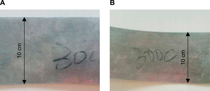
FIGURE 1. FeCrAl alloy plates: (A) 60% total thickness reduction and (B) 90% total thickness reduction.
Nano-indentation tester with the thermal drift of 0.05 nm/s was used to carry out the test. The diamond Berkovich indenter with the three-sided pyramid was used in this study. In a light-water reactor, light water was used as the primary coolant, with a temperature of about 350°C (Saunders et al., 1997; Park et al., 2015). Therefore, the nano-indentation creep tests were carried out at the temperature of 350°C. Four different applied loads of 100 mN, 200 mN, 300 mN, and 400 mN were used for creep generation. The loading time from the 0 mN to the applied loads was fixed as 30 s, the holding time of the applied loads was set as 600 s, and the unloading time from the applied loads to 0 mN was fixed as 60 s. The time, displacement, and applied loads were recorded automatically during the tests.
Results
Microstructure of FeCrAl Alloy
The microstructure of FeCrAl alloy is shown in Figure 2. As shown in Figures 2A,B, the grain boundaries were clear for the alloy, with 60% total thickness reduction. The grain deformation was slight, and the grain size was about 220 μm, even though it was slightly elongated to the rolling direction. For the alloy with 90% total thickness reduction, as shown in Figures 2C,D, the grain deformation was very significant, and it was challenging to find an equal-axis grain. All grains were elongated to the rolling direction, and the grain size was about 100 μm, which was smaller than that of the alloy with 60% total thickness reduction. The grain size was not uniform, and the grain length was much larger in the rolling direction. Therefore, the grains became flat and were elongated along the rolling direction after the hot-rolling due to the rolling force perpendicular to the rolling surface. This phenomenon accounted for the rolling process providing the energy for the dynamic recrystallization of the crystal. The larger the rolling thickness reduction was, the more energy was provided to the crystal and the more grains completed the dynamic recrystallization process. Similar results were also found by Yamamoto et al., (2015) and Zheng et al., (2019). In addition, the tiny black dots were defects or inclusions which were produced during metallurgy.
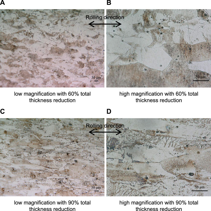
FIGURE 2. Optical microscope images of FeCrAl alloy. (A) Low magnification with 60% total thickness reduction, (B) high magnification with 60% total thickness reduction, (C) low magnification with 90% total thickness reduction, and (D) high magnification with 90% total thickness reduction.
Nano-Indentation Creep Test
The steady-state creep strain rate also satisfies the power-law creep model in the nano-indentation creep test as follows (Goodall and Clyne, 2006):
where
where F is the applied load and S is the projected contact area. For the used Berkovich indenter in the tests,
where
The values of F,
The nano-indentation creep test results of the indentation load and the corresponding displacement are shown in Figure 3. As shown in Figure 3, the displacement increased with increase of load. When the load was larger than 100 mN, the displacement first decreased to a certain value and then kept on increasing in the load holding stage or the creep stage. The possible reason was that the loading rate was slightly large, because this phenomenon did not appear in the load of 100 mN.
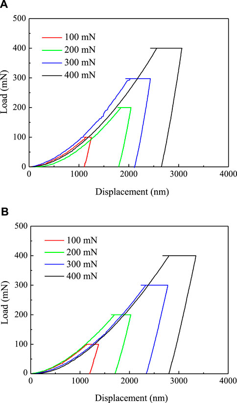
FIGURE 3. Nano-indentation creep test results of the indentation load and the corresponding displacement for FeCrAl alloys at the temperature of 350°C: (A) 60% total thickness reduction and (B) 90% total thickness reduction.
The nano-indentation creep test results are shown in Figure 4 for the variation of the creep displacement with the creep time at the temperature of 350°C. As shown in Figure 4, the creep displacement increased with the applied load increase because the creep deformation increased with the applied load. Also, as shown in Figure 4, the creep displacement curves were similar to those of the traditional creep tests. They could be divided into two creep stages, that is, the primary creep stage and the steady-state creep stage. The primary creep stage was much shorter. As shown in Figure 4, after the time of 200 s, all curves almost reached the steady-state creep stage. Therefore, the power-law creep model was fitted using the curves after the time of 200 s.
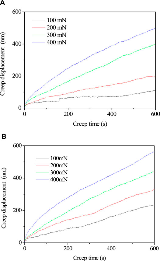
FIGURE 4. Nano-indentation creep test results of FeCrAl alloys at the temperature of 350°C: (A) 60% total thickness reduction and (B) 90% total thickness reduction.
When the values of F, hc, and hpc were measured from the nano-indentation creep test, the values of
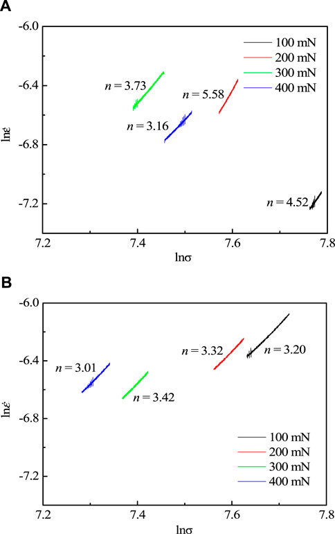
FIGURE 5. Variation of n under different applied loads for the FeCrAl alloy at the temperature of 350°C: (A) 60% total thickness reduction and (B) 90% total thickness reduction.
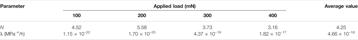
TABLE 2. Nano-indentation creep test results for FeCrAl alloy with 60% total thickness reduction.
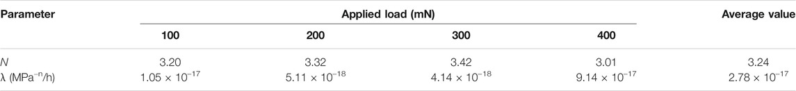
TABLE 3. Nano-indentation creep test results for FeCrAl alloy with 90% total thickness reduction.
Based on the test results of Table 2 and Table 3, the power-law creep model for the FeCrAl alloy was obtained as follows:
with 60% total thickness reduction,
with 90% total thickness reduction. The variations of
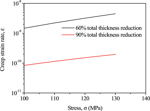
FIGURE 6. Comparison of
Conclusion
The effect of a process condition of hot-rolling thickness reduction on the creep properties of FeCrAl alloys was investigated using a nano-indentation creep test at the temperature of 350°C. The microanalysis results indicated that grain size became smaller with the increase of the hot-rolling thickness reduction, and the grain elongated to the hot-rolling direction. The power-law creep model was obtained using the nano-indentation creep tests. The test results showed that the power-law creep stress exponent was about four, and the creep resistance increased by the increase of the hot-rolling thickness reduction.
Data Availability Statement
The original contributions presented in the study are included in the article/Supplementary Material; further inquiries can be directed to the corresponding authors.
Author Contributions
All authors listed have made a substantial, direct, and intellectual contribution to the work and approved it for publication.
Funding
The financial support from the Project of National Natural Science Foundation of China (No. 51705078), International Sci & Tech Cooperation Program of GuangDong Province (2019A050510022), Guangdong Major Project of Basic and Applied Basic Research (2019B030302011), and Key-Area Research and Development Program of GuangDong Province (2019B010943001, 2017B020235001).
Conflict of Interest
Author XY was employed by the company Suzhou Nuclear Power Research Institute Co. Ltd.
The remaining authors declare that the research was conducted in the absence of any commercial or financial relationships that could be construed as a potential conflict of interest.
Abbreviations
A, power-law creep constant; F, applied load; hc, creep displacement; hpc, contact displacement; n, power-law creep stress exponent; S, projected contact area;
References
Dryepondt, S., Pint, B. A., and Lara-Curzio, E. (2012). Creep Behavior of Commercial FeCrAl Foils: Beneficial and Detrimental Effects of Oxidation. Mater. Sci. Eng. A 550, 10–18. doi:10.1016/j.msea.2012.03.031
Fischer-Cripps, A. C. (2006). Critical Review of Analysis and Interpretation of Nanoindentation Test Data. Surf. Coat. Tech. 200, 4153–4165. doi:10.1016/j.surfcoat.2005.03.018
Gamble, K. A., Barani, T., Pizzocri, D., Hales, J. D., Terrani, K. A., and Pastore, G. (2017). An Investigation of FeCrAl Cladding Behavior under normal Operating and Loss of Coolant Conditions. J. Nucl. Mater. 491, 55–66. doi:10.1016/j.jnucmat.2017.04.039
Goodall, R., and Clyne, T. W. (2006). A Critical Appraisal of the Extraction of Creep Parameters from Nanoindentation Data Obtained at Room Temperature. Acta Materialia 54 (20), 5489–5499. doi:10.1016/j.actamat.2006.07.020
Kamikawa, R., Ukai, S., Kasai, S., Oono, N., Zhang, S., Sugino, Y., Masuda, H., and Sato, E. (2018). Cooperative Grain Boundary Sliding in Creep Deformation of FeCrAl-ODS Steels at High Temperature and Low Strain Rate. J. Nucl. Mater. 511, 591–597. doi:10.1016/j.jnucmat.2018.04.050
Kang, K. J., and Mercer, C. (2007). Creep Properties of a Thermally Grown Alumina. Mat. Sci. Eng. A-struct. 478 (1), 154–162.
Li, C., Ding, J., Zhu, F., Yin, J., Wang, Z., Zhao, Y., and Kou, S. (2019). Indentation Creep Behavior of Fe-Based Amorphous Coatings Fabricated by High Velocity Oxy-Fuel. J. Non-Crystalline Sol. 503-504, 62–68. doi:10.1016/j.jnoncrysol.2018.09.018
Masuda, H., Tobe, H., Sato, E., Sugino, Y., and Ukai, S. (2016). Two-dimensional Grain Boundary Sliding and Mantle Dislocation Accommodation in ODS Ferritic Steel. Acta Materialia 120, 205–215. doi:10.1016/j.actamat.2016.08.034
Moalem, M., and Olander, D. R. (1991). Oxidation of Zircaloy by Steam. J. Nucl. Mater. 182, 170–194. doi:10.1016/0022-3115(91)90428-A
Park, D. J., Kim, H. G., Park, J. Y., Jung, Y. I., Park, J. H., and Koo, Y. H. (2015). A Study of the Oxidation of FeCrAl alloy in Pressurized Water and High-Temperature Steam Environment. Corrosion Sci. 94, 459–465. doi:10.1016/j.corsci.2015.02.027
Pint, B. A., Terrani, K. A., Brady, M. P., Cheng, T., and Keiser, J. R. (2013). High Temperature Oxidation of Fuel Cladding Candidate Materials in Steam-Hydrogen Environments. J. Nucl. Mater. 440, 420–427. doi:10.1016/j.jnucmat.2013.05.047
Saunders, S. R. J., Evans, H. E., Li, M., Gohil, D. D., and Osgerby, S. (1997). Oxidation Growth Stresses in an Alumina-Forming Ferritic Steel Measured by Creep Deflection. Oxid Met. 48, 189–200. doi:10.1007/bf01670498
Sebastiani, M., Bemporad, E., Carassiti, F., and Schwarzer, N. (2011). Residual Stress Measurement at the Micrometer Scale: Focused Ion Beam (FIB) Milling and Nanoindentation Testing. Phil. Mag. 91, 1121–1136. doi:10.1080/14786431003800883
Tang, C., Jianu, A., Steinbrueck, M., Grosse, M., Weisenburger, A., and Seifert, H. J. (2018). Influence of Composition and Heating Schedules on Compatibility of FeCrAl Alloys with High-Temperature Steam. J. Nucl. Mater. 511, 496–507. doi:10.1016/j.jnucmat.2018.09.026
Terrani, K. A., Karlsen, T. M., and Yamamoto, Y. (2016). Input Correlations for Irradiation Creep of FeCrAl and SiC-Based on In-Pile Halden Test Results, Technical Report ORNL/TM-2016/191. ORNL. doi:10.2172/1259428
Terrani, K. A., Zinkle, S. J., and Snead, L. L. (2014). Advanced Oxidation-Resistant Iron-Based Alloys for LWR Fuel Cladding. J. Nucl. Mater. 448, 420–435. doi:10.1016/j.jnucmat.2013.06.041
Thornby, J., Harris, A., Bird, A., Beake, B., Manakari, V. B., Gupta, M., and Haghshenas, M. (2021). Micromechanics and Indentation Creep of Magnesium Carbon Nanotube Nanocomposites: 298 K-573 K. Mater. Sci. Eng. A 801, 140418. doi:10.1016/j.msea.2020.140418
Ukai, S., Kato, S., Furukawa, T., and Ohtsuka, S. (2020). High-temperature Creep Deformation in FeCrAl-Oxide Dispersion Strengthened alloy Cladding. Mater. Sci. Eng. A 794, 139863. doi:10.1016/j.msea.2020.139863
Yamamoto, Y., Pint, B. A., Terrani, K. A., Field, K. G., Yang, Y., and Snead, L. L. (2015). Development and Property Evaluation of Nuclear Grade Wrought FeCrAl Fuel Cladding for Light Water Reactors. J. Nucl. Mater. 467, 703–716. doi:10.1016/j.jnucmat.2015.10.019
Zhang, H., Liu, Y., Wang, L., Sun, F., Fan, X., and Zhang, G. (2019). Indentation Hardness, Plasticity and Initial Creep Properties of Nanosilver Sintered Joint. Results Phys. 12, 712–717. doi:10.1016/j.rinp.2018.12.026
Zheng, J., Jia, Y., Du, P., Wang, H., Pan, Q., Zhang, Y., Liu, C., Zhang, R., and Qiu, S. (2019). Control of Laves Precipitation in a FeCrAl-Based alloy through Severe Thermomechanical Processing. Materials 12 (18), 2939. doi:10.3390/ma12182939
Keywords: FeCrAl, creep, process condition, hot-rolling, nano-indentation creep
Citation: Lai HS, Guo J, Zhang S, Yu X, Meng F, Zhao Z and Zhou W (2021) Effect of Rolling Deformation on Creep Properties of FeCrAl Alloys. Front. Energy Res. 9:663578. doi: 10.3389/fenrg.2021.663578
Received: 03 February 2021; Accepted: 31 May 2021;
Published: 25 June 2021.
Edited by:
Jun Wang, University of Wisconsin-Madison, United StatesReviewed by:
Zhangjian Zhou, University of Science and Technology Beijing, ChinaXiazi Xiao, Central South University, China
Copyright © 2021 Lai, Guo, Zhang, Yu, Meng, Zhao and Zhou. This is an open-access article distributed under the terms of the Creative Commons Attribution License (CC BY). The use, distribution or reproduction in other forums is permitted, provided the original author(s) and the copyright owner(s) are credited and that the original publication in this journal is cited, in accordance with accepted academic practice. No use, distribution or reproduction is permitted which does not comply with these terms.
*Correspondence: Zilong Zhao, zhaozlong@mail.sysu.edu.cn; Wenzhong Zhou, zhouwzh3@mail.sysu.edu.cn