Elucidating fault-related fold mechanics: a 2D finite element analysis of bending, slip, and buckling mechanisms
 Anis Khalifeh-Soltani1
  Seyed Ahmad Alavi1 Mohammad Reza Ghassemi2,3 Mehdi Ganjiani4
  Reza Derakhshani5,6*
- 1Department of Sedimentary and Oil Basins, Faculty of Earth Sciences, Shahid Beheshti University, Tehran, Iran
- 2Research Institute for Earth Sciences, Geological Survey of Iran, Tehran, Iran
- 3School of Geology, College of Science, University of Tehran, Tehran, Iran
- 4Department of Mechanical Engineering, University of Tehran, Tehran, Iran
- 5Department of Geology, Shahid Bahonar University of Kerman, Kerman, Iran
- 6Department of Earth Sciences, Utrecht University, Utrecht, Netherlands
Fault-related folds are present in most tectonic settings and may serve as structural traps for hydrocarbons. Due to their economic importance, many kinematic models present for them. Unfortunately, most of them have predominantly concentrated on the sliding mechanism parallel to the layering and often ignore the integral role of buckling in folding processes. This study is at the forefront of exploring the interplay among, sliding, buckling, and bending in the formation of the three fundamental types of fault-related folds: detachment, fault-propagation, and fault-bend folds. To this end, we developed five sets of two-dimensional (2D) finite element models, embodying both elastic and elastic-plastic behaviors. Our results indicate that sliding parallel to layering and faults, in conjunction with buckling, are the predominant mechanisms in fault-related folding. The strain ellipse patterns in our models are consistent with those observed in buckling models, thus affirming the significance of buckling in these geological structures. Furthermore, our models demonstrate that fault slip diminishes from the periphery towards the center in all three types of fault-related folds, in contrast to interlayer slip, which intensifies from the edge towards the center. In essence, a diminution in fault slip at the center is balanced by an augmentation in interlayer slip, leading to thickening and buckling. The genesis of all three fault-related fold types is attributed to the reduction in fault slip, with their distinctiveness defined by the location of this reduction: at the detachment fault tip for detachment folds, at the ramp tip for fault-propagation folds, and at the upper flat for fault-bend folds.
1 Introduction
Fault-related folds, evident in both compressional and extensional regimes (Mitra, 1993; McClay, 2011; Morley et al., 2011), are of significant geological interest, particularly due to their potential as structural traps for hydrocarbon resources (McClay, 1995; Kent and Dasgupta, 2004). Owing to their economic importance, numerous researchers have investigated fault-related folds through various approaches such as field studies, seismic research, sandbox experiments, and numerical modelling, as illustrated in works by McClay (1995), Allmendinger (1998), Hughes and Shaw (2015) and Ghanbarian et al. (2021). Various numerical modeling techniques have been employed in the study of geological structures. These include finite element analysis (Smart et al., 2012; Yang et al., 2017; Li et al., 2019; Khalifeh-Soltani et al., 2021a; Khalifeh-Soltani et al., 2021b; Khalifeh-Soltani et al., 2021c; Khalifeh-Soltani et al., 2023a; Khalifeh-Soltani et al., 2023b), boundary element analysis (Cooke and Pollard, 1997; Desai et al., 2011; Maerten et al., 2014), and discrete element analysis (Finch et al., 2003; Hardy and Finch, 2006). Moreover, numerical models that utilize velocity vectors have been developed for fault-related folds (e.g., Johnson and Berger, 1989; Hardy and Poblet, 1995; Hardy et al., 1996; Allmendinger, 1998; Cardozo, 2005).
Fault-related folds consist of three end-members: fault-bend folds (e.g., Berger and Johnson, 1980; Suppe, 1983; Brandes and Tanner, 2014), fault-propagation folds (e.g., Mitra, 1990; Suppe and Medwedeff, 1990; Brandes and Tanner, 2014), and detachment folds (e.g., Epard and Groshong, 1995; Homza and Wallace, 1995; Poblet and McClay, 1996; Homza and Wallace, 1997). The fault-bend fold developed above a flat-ramp-flat that is called a single-step fault-bend fold. Fault-propagation folds are caused by the gradual reduction of slip on a propagating thrust fault (Suppe and Medwedeff, 1990). These folds are characterized by steep or overturned forelimbs (Suppe and Medwedeff, 1990; Hughes et al., 2014; Hughes and Shaw, 2015). Detachment folds may form above or below a detachment or a decollement (e.g., Poblet and Hardy, 1995; Poblet et al., 1997; Peacock et al., 2000). The detachment fold grows by moving the detachment layer’s particles toward the centre of the fold (Homza and Wallace, 1995; Poblet and McClay, 1996).
Since fault-related folds can be hydrocarbon traps, a correct understanding of their kinematics can help us determine the temporal relationship of structure growth with maturity and migration of hydrocarbon resources. On the other hand, the strain distribution in the reservoir can control its permeability (Hughes and Shaw, 2015). Therefore, there is a need for a kinematic model that can clarify the mechanisms governing these folds and provide its stress and strain history, which, unfortunately, most of the kinematic-geometric models that have been presented so far, despite their advantages, have some limitations: 1) The primary assumption of these models is based on some geometric simplifications; for example, they consider the length and thickness of the layers to be constant during folding, which is not the case in real examples, and hence they cannot accurately represent the geometry of real examples, 2) The role of effective parameters on folding, such as the mechanical properties of materials, variation in stress and strain, and the interface characteristics of layers, are not considered (Allmendinger, 1998; Logan, 2010; Smart et al., 2012), and 3) Most presented kinematic models are based on the classical kink-band migration mechanism. The kink band migration model also has limitations: i) The conditions for forming kink folds are also ideal. According to Ramsay and Huber (1987), when the contrast in thickness and viscosity of the layers is high, kink folds are created. In natural examples, except for the viscosity contrast of the decollement and other layers, the viscosity and thickness of the sedimentary layers forming the fault-related folds are usually similar, ii) The simple shear parallel to the layering creates the kink folds (e.g., Ramsay and Huber, 1987). While buckling mechanism, which plays a role in the formation of fault-related folds, is neglected in these models, especially in detachment and fault-propagation folds (Barani, 2012; Li et al., 2018; Butler et al., 2020; Ghanbarian and Derakhshani, 2022; Rashidi et al., 2023).
Unlike kinematic-geometric models, geomechanical models do not have these limitations: 1) These models have no geometric simplifications, the length and thickness of the layers change during folding, so they create folds closer to actual examples (Smart et al., 2012), 2) They consider the influence of the mechanical properties of materials, the characteristics of the interface of layers and faults, 3) they can provide the evolution of stress and strain at any moment and any location of the model, and 4) Their setup does not limit the participation of interlayer sliding, bending and buckling mechanisms. Therefore, geomechanical models provide a more appropriate insight into the mechanism of fault-related folds than kinematic-geometric models. This study examines the mechanics of fault-related folds through a set of geomechanical models for the first time.
Since inter-layering slip, buckling, and bending mechanisms influence the development of folds (Twiss and Moores, 1992). Here, we investigate the contribution of each of them in the development of fault-related folds through five series of 2D finite element models. For this purpose, we first simulate three end members of fault-related folds (reference models) using the 2D finite element method (Series R). Then, we fold single-layers and multi-layers by bending and buckling mechanisms with two different elastic and elastic-plastic rheologies (Series A and B). Also, by removing interlayer slip, we examine its effect on buckling and bending (Series C and D). Finally, the strain ellipses of these models (Series A- D) are compared with reference models (Series R).
2 Modeling
In this study, five series of 2D elastic and elastic-plastic finite element models to determine the contribution of each of the mechanisms of bending, buckling and inter layering slip in creating fault-related folds are presented (R, A, B, C and D). All the models of this study ran in ABAQUS™ software (version 2017).
The first series (R) consists of three elastic-plastic R1, R2, and R3 models, which simulate the three end members of fault-related folds, i.e., detachment, fault-propagation, and fault-bend folds. In fact, these are reference models to which the results of other models are compared. Series A is a set of elastic and elastic-plastic models that simulate bending at single-layer and multi-layer (with interlayer slip). The elastic and elastic-plastic models are listed in Table 1. Series B simulates buckling at single-layer and multi-layer (with interlayer slip) by a set of elastic and elastic-plastic models. As well as series C simulates non-slip buckling in single-layer and multi-layer modes. Series D investigates the role of non-slip bending and buckling. The difference in the buckling models of series C and D is in the equations used for modeling, which will be described in the following sections.
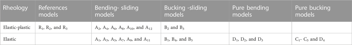
TABLE 1. Rheology and folding mechanism of the models.
2.1 Modeling equations
In all the elastic-plastic models in series R, A, B and D (Table 1), Hooke’s law for the portion of elastic behaviour of the models is used, and the standard Mohr-Coulomb criterion for the part of elastic behaviour of the models is used. Only Hooke’s law for the elastic models in series A, B, C, and D is used (Table 1). In series C, the buckling equation is used instead of the standard Mohr-Coulomb criterion to simulate buckling folding. It is described below.
Abaqus software uses an incremental loading pattern, QN, to calculate the eigenvalue buckling:
Where K0NM is the stiffness matrix corresponding to the base state, considering that the models presented in this study include one step (buckling step), their base state is the same as the pre-deformation model, so the preload effects (PN) are not present in them. KΔNM is the initial differential stress and load stiffness matrix due to the incremental loading pattern (QN). λi is the eigenvalues. υiM is the buckling mode shapes (eigenvectors). M and N refer to degrees of freedom of the whole model, and i refers to the ith buckling mode.
Here, we examine three outputs, elastic and plastic strain and Mises stress of elastic-plastic models, and two outputs of elastic stress and Mises stress of elastic models. Elastic and plastic strains represent reversible and permanent deformation of the models, respectively. Mises stress is a measure of the combined magnitude of all stress components (tensile, compression, and shear) at any point. Therefore, it is extremely useful for predicting the failure modes in structures.
2.2 Geometry and mechanical properties of models
The dimensions (length and thickness) and mechanical properties of all the models are similar (Figure 1; Table 2). The material properties of the layers (i.e., density, Young’s modulus, Poisson’s ratio, cohesion, internal friction angle and dilation angle) are listed in Table 2. Like our previous works, these data were derived from the results of rock mechanics experiments carried out by the National Iranian South Oilfields Company (Khalifeh-Soltani et al., 2021a; Khalifeh-Soltani et al., 2021b; Khalifeh-Soltani et al., 2023a).
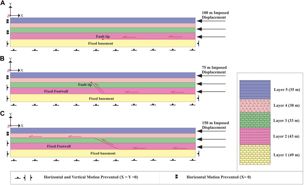
FIGURE 1. Boundary conditions of series R models; (A) detachment fold model (R1), (B) fault-propagation fold model (R2), and (C) fault-bend fold model (R3).
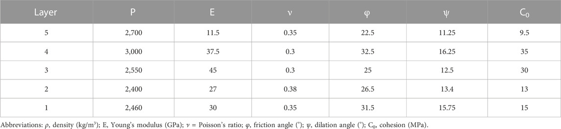
TABLE 2. Material properties are used in all finite element models (Khalifeh-Soltani et al., 2021b; Khalifeh-Soltani et al., 2021c).
Series R contains five layers. The ramp dip in the models of the fault-propagation (R2) and fault-bend folds (R3) is 45° and 25°, respectively (Figure 1). While series A, B, C and D include four layers (Figure 2). Because layer 1) does not play a role in folding in reference models (R), it has been omitted.
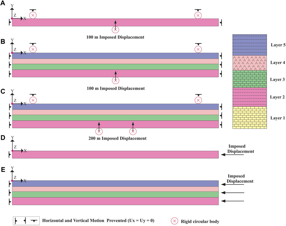
FIGURE 2. Boundary conditions of the models; (A) single-layer bending at three points (A1 to A8 models), (B) multi-layer bending at three points (A9, A10, D1, and D2 models), (C) multi-layer bending at four points (A11, A12 and D3 models), (D) single-layer buckling (B1, B2, C1 to C4 models, (E) multi-layer buckling (B3 to B5, C5 and D4 models).
It is necessary to mention here that, since fault-related folds are mainly created in sedimentary rocks, and except for detachment levels, the difference in mechanical properties in layers is not significant, the results of this study can be valid even for other regions. However, to generalize the results to other areas, the lithology influence should not be ignored.
2.3 Friction coefficient
For the interaction of fault and layers in series R, friction coefficients of 0.01 and 0.25 are considered, respectively. A friction coefficient of 0.25 is considered for the interaction of layering surfaces in multi-layer models of series A and B, while multi-layer models of series C and D have no interlayer slip.
2.4 Setup and boundary conditions
The models presented here include one step, and displacement is applied to simulate folding in that step. The boundary conditions of the reference models (R) are shown in Figure 1. As shown in all three models, the model’s left side is not allowed to move horizontally during folding (X = 0; Where X, Y, and Z are displacements along the X, Y, and Z-axes, respectively). At the same time, displacement is applied to the right side of the model (Figure 1). The displacement in the detachment, fault-propagation, and fault-bend fold models is 100, 75, and 150 m, respectively. Footwalls in the fault-propagation and fault-bend fold models and also layer (1) (the basement) in the detachment fold model are fixed (X=Y=0).
Figures 2A–C shows the boundary conditions of the models that simulate single-layer and multi-layer bending with slip (series A) and non-slip (D1 to D3 models). Figures 2A, B show the boundary conditions of single-layer and multi-layer bending at three points. Figure 2C shows the boundary conditions of multi-layer bending at four points. In all three cases, the right and left sides of the model are not allowed to move horizontally and vertically (X = Y = 0). Also, in all three cases, two rigid circular bodies with a diameter of 40 m are fixed on the model top at a distance of 120 m from the model’s edge (X = Y =0). In the case of bending models at three points, a rigid circular body is located under the centre of the models, and the bending at three points is simulated by its upward movement (100 m) (Figures 2A, B). In the case of bending models at four points, two rigid circular bodies are located under the model centre at a distance of 200 m from each other; the bending at four points is simulated by their simultaneous upward movement (100 m) (Figure 2C). Figure 2D shows the boundary conditions of buckling in single-layer models of series B and C. In the same way, Figure 2E shows the boundary conditions of buckling in multi-layer models for both sliding (series B) and non-sliding conditions (series C). In all models shown in Figures 2D, E, the model’s left side cannot move in the horizontal direction (X = 0), while the displacement is applied to the model’s left side to simulate buckling (Figures 2D, E). Of course, the amount of displacement is different in these models (Actually, models with larger displacements have been added to examine the results more precisely).
All models’ meshes are square, with 10 × 10 m dimensions. We use the deformation of these squares to estimate the final strain ellipse of the models. Of course, in the basement and footwalls of the reference models (series R), the dimensions of meshes are large and irregular because these parts are fixed during folding.
3 Modeling results
Here, we present five series of 2D elastic and elastic-plastic finite element models to determine the contribution of interlayer slip buckling, and bending mechanisms to develop fault-related folds. The results are as follows.
3.1 Reference models (series R)
Series R includes three reference models, which simulate detachment (R1), fault-propagation (R2), and fault-bend folds (R3). Then, the geometric evolution, distribution of elastic and plastic strains, and Mises stress in these models are investigated.
The detachment fold model creates a symmetric fold in which its amplitude and wavelength increase with displacement increases (Figures 3A–C). The elastic strain is distributed throughout the model and is mainly concentrated at the crest and fold limbs (Figures 3A–C). Mises stress is distributed mainly in the third and fourth layers (especially the limbs) (Figure 3D). The plastic strain is concentrated at the detachment fault tip and distributed towards the axial surfaces (Figure 3E). The maximum fault slip occurs at the model’s boundary but decreases towards the detachment fault tip. On the contrary, the amount of interlayer slip is zero at the borders of the model and increases towards the model’s centre (Figures 3A–C). In addition, the fold crest moves forward during folding (Figures 3A–C).
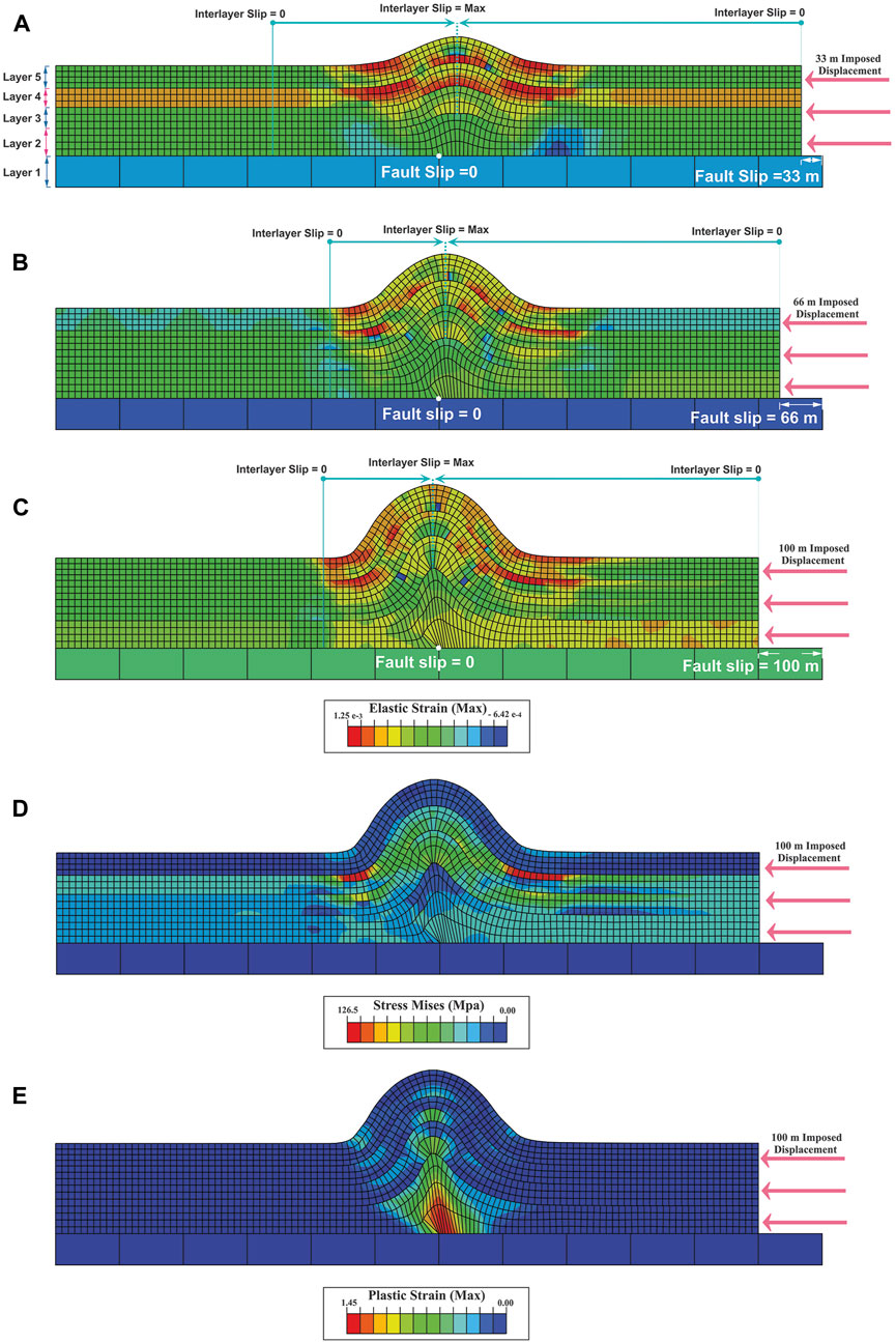
FIGURE 3. Distribution of elastic strain and geometry of detachment fold model (R1) in; (A) 33 m of displacement, (B) 66 m of displacement, (C) 100 m of displacement, (D) distribution of Mises stress in 100 m of displacement, (E) plastic strain distribution in 100 m of displacement. The maximum and minimum slip points during folding are shown in turquoise colour (A–C). Layers one to five are shown in (A)
In the fault-propagation fold model, the amplitude and wavelength of the fold increase while the interlimb angle decreases during the folding, and the fold becomes tighter (Figures 4A–C). The elastic strain is distributed throughout the model and is mainly concentrated in the crest and limbs at the fourth and fifth layers (Figures 4A–C). Mises stress is more concentrated in the fourth and fifth layers (Figure 4D). Plastic strain is localized on the fault surface, the fault tip, and the forelimb (Figure 4E). Similar to the detachment fold model, the maximum fault slip occurs at the model’s boundary (75 m), decreasing towards the model’s centre (38 m) and reaching zero at the fault tip (Figures 4A–C). On the contrary, at the model border, interlayer slip is zero and increases towards the centre.
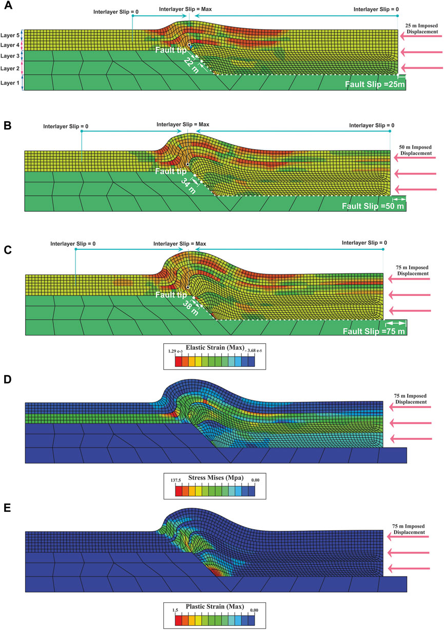
FIGURE 4. Distribution of elastic strain and geometry of fault-propagation fold model (R2) in; (A) 25 m of displacement, (B) 50 m of displacement, (C) 75 m of displacement, (D) distribution of Mises stress in 75 m of displacement, (E) plastic strain distribution in 75 m of displacement. The maximum and minimum interlayer slip points during folding are shown in turquoise colour (A–C). Slip changes on the flat-ramp are shown in white, and blak shows the ramp tip. Layers one to five are shown in (A)
In the fault-bend model, the fold amplitude and wavelength increase with increasing shortening (Figures 5A–C). In the early stages of folding, the elastic strain is distributed throughout the fourth and fifth layers (Figure 5A). But with the progress of folding, it is concentrated in the fold limbs (Figure 5C). Mises stress is focused on the second to fourth layers (Figure 5D). The plastic strain is concentrated on the fault surface, fault tip and forelimb of the fold (Figure 5E). The maximum fault slip is observed at the model boundary (150 m), decreasing towards the ramp (80 m) and reaching zero in the upper flat (Figures 5A–C). While the interlayer slip is zero at the model’s boundary and maximized at the forelimb (Figures 5A–C).
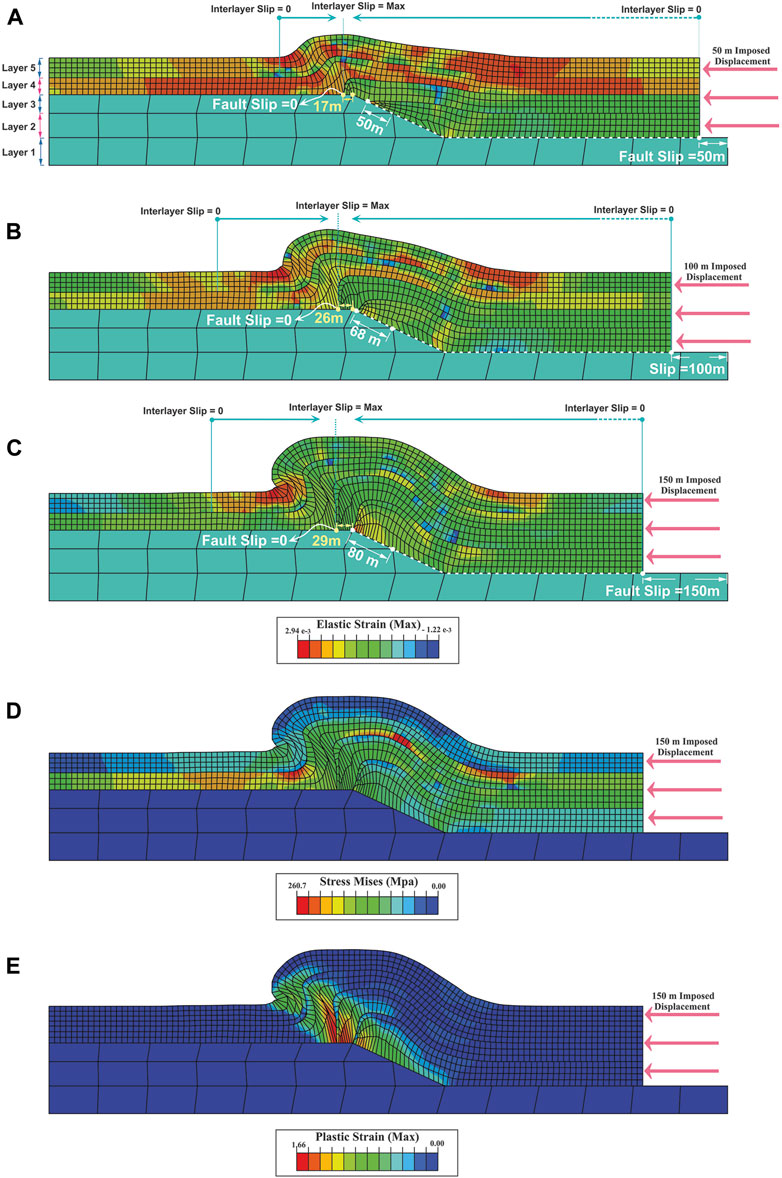
FIGURE 5. Distribution of elastic strain and geometry of fault-bend fold model (R3) in; (A) 50 m of displacement, (B) 100 m of displacement, (C) 150 m of displacement, (D) distribution of Mises stress in 150 m of displacement, (E) plastic strain distribution in 150 m of displacement. The maximum and minimum interlayer slip points during folding are shown in turquoise colour (A–C) (A–C). Slip changes on the flat-ramp-falt are shown in white (layer 2) and yellow (layer 3). Layers one to five are shown in (A)
3.2 Bending-sliding folding in multi-layer and bending in single-layer (series A)
Series A consists of twelve models, and the first eight models (A1 to A8) simulate bending in the single-layer with both elastic and elastic-plastic behaviours. The odd models are elastic (i.e., A1, A3, A5, and A7), while even models are elastic-plastic (i.e., A2, A4, A6, and A8) (Table 1). Figure 2A shows the boundary conditions of these eight models. The results show that all the elastic models are entirely run until the end of the applied displacement (Figures 6A, C, E, G). While the elastic-plastic models stop after some displacement (Figures 6B, D, F, H). In elastic models, the Mises stress and elastic strain are concentrated in the model’s centre and the hinge zone (Figures 6A, C, E, G). In elastic-plastic models, the Mises stress and elastic strain are localized in the central part of the model and at the contact surface of the rigid circular bodies with the layers (Figures 6B, D, F, H). While in elastic models, the Mises stress and elastic strain are concentrated on the opposite side of the rigid circular bodies (Figures 6A, C, E, G). In elastic-plastic models, plastic strain is also localized in the centre of the model (Figures 6B, D, F, H).
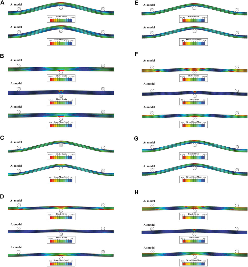
FIGURE 6. Distribution of elastic, plastic strains, and Mises stress in single-layer elastic (A, C, E, G) and elastic-plastic (B, D, F, H) bending models. The odd models A1, A3, A5 and A7 are elastic, the even models A2, A4, A6 and A8 are elastic-plastic.
The next four models (A9 to A12) create bending in a multi-layer (Figures 7, 8). The rheology in these models is different; the odd and even models are elastic and elastic-plastic, respectively (Table. 1; Figures 7, 8). The A9 and A10 models simulate bending at three-point with interlayer slip. Figure 2B shows their boundary conditions. The elastic strain is distributed throughout the A9 model (Figure 7A). The Mises stress is mainly distributed in layers (2) to (4) (Figure 7A). The elastic strain and Mises stress are increased in the A10 model compared to the A9 model (Figure 7). The plastic strain is concentrated around the rigid circular bodies (Figure 7B). The geometry of the elastic and elastic-plastic models is almost the same; only in the elastic-plastic models the rigid circular bodies are indented at the contact surface with the layers, indicating the model’s plastic rheology (Table. 1; Figure 7). Both elastic (A9) and elastic-plastic (A10) models are run until the end of the applied displacement. In contrast, the single-layer elastic-elastic models stopped after a few displacements. Maybe this is due to the effect of interlayer slip in multi-layer models; the results of the next series will reveal this problem (series D).
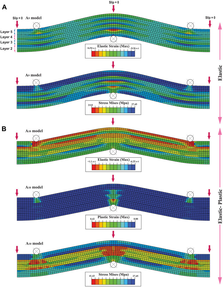
FIGURE 7. Distribution of elastic strain and Mises stress in multi-layer bending model at the three-point for; (A) elastic (A9), and (B) elastic-plastic models (A10). Layers one to five are shown in (A)
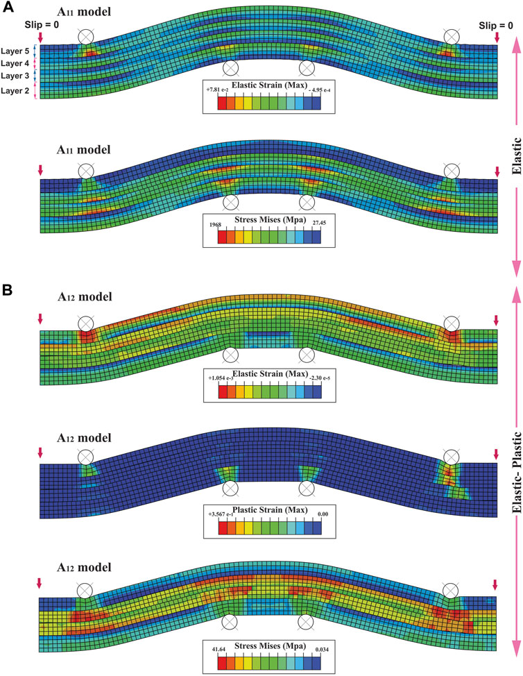
FIGURE 8. Distribution of elastic strain and Mises stress in multi-layer bending model at the four-point for; (A) elastic (A11), and (B) elastic-plastic models (A12). Layers one to five are shown in (A)
In the same way, A11 and A12 models simulate bending at four points with interlayer slip (Figure 8), whose boundary conditions are shown in Figure 2C The elastic strain and Mises stress are distributed throughout the A11 model and are localized at the contact surface of the rigid circular bodies with the layers (Figure 8A). The Mises stress and elastic strain are increased in the A12 model compared to the A11 model (Figure 8). The plastic strain is concentrated around the rigid circular bodies (Figure 8B). Also, like the A10 model, in the A12 model, the rigid circular bodies are indented at the contact surface with the layers, indicating the model’s plastic rheology (Figures 7B, 8B).
Investigation slip variations in multi-layer models showed that in the hinge surface and the borders of the A9 and A10 multi-layer models, the slip is zero, and it towards limbs becomes maximum (Figure 7). While in models A11 and A12, the slip is zero only at the borders of the models, and it without a specific pattern is distributed throughout the model (Figure 8).
3.3 Buckling-sliding folding in multi-layer and buckling in single-layer (series B)
B series consists of five models that simulate single-layer and multi-layer buckling (with slip). The B1 and B2 single-layer models are elastic and elastic-plastic, respectively (Table. 1; Figure 9A). To summarize, only layer 2) is modelled for single-layer bending. The boundary conditions of these models are shown in Figure 2D. The B1 elastic model is run until the end of applied displacement (Figure 9A). Nevertheless, any fold is not created, and only the thickness of the layer increases as pure shear (Figure 9A). Mises stress, and elastic strain are uniformly distributed throughout the fold and are localized at the model’s left border (Figure 9A). The B2 elastic-plastic model stops after a few displacements and does not form any fold (Figure 9A). Mises stress, elastic strain, and plastic strain are concentrated at the model’s left border as in the B2 model (Figure 9A).
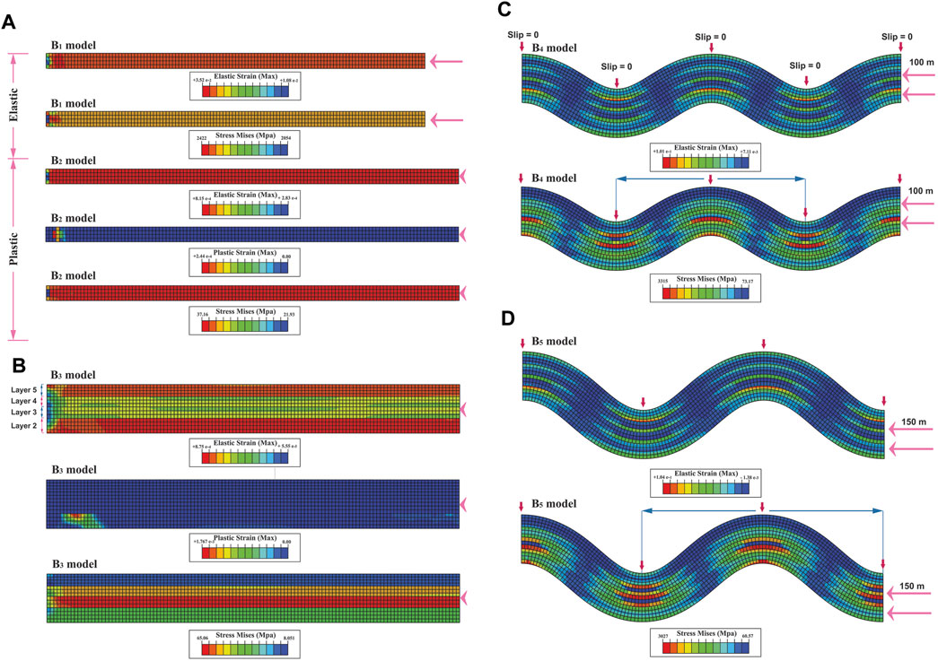
FIGURE 9. (A) Distribution of elastic and plastic strains and Mises stress in single-layer buckling models with elastic (B1) and elastic-plastic rheologies (B2). Distribution of elastic and plastic strains and Mises stress in multi-layer buckling models for; (B) elastic-plastic rheology (B3), (C, D) elastic rheology (B4 and B5). Layers one to five are shown in (B). The blue arrow shows the half-wavelength from which the strain ellipse presented in Figure 13 was extracted.
The B3, B4 and B5 models simulate multi-layer buckling with interlayer slip (Figures 9B–D). The boundary conditions of these models are shown in Figure 2E. The rheology in the B3 model and B4 and B5 models are elastic-plastic and elastic, respectively (Figures 9B–D). The difference between the B4 and B5 models is in the amount of displacement; their displacements are 100 and 150 m, respectively (Figures 9C, D). The B3 multi-layer model, like the B1 and B2 single-layer models, stops after a few displacements and does not create any fold; Just the thickness of the layers increases as pure shear (Figure 9B). The elastic strain is distributed throughout the model (Figure 9B). The Mises stress is the maximum in the third layer. The plastic strain is localized at the base of the model’s left side (Figure 9B). In the B4 model, a fold with a full wavelength is created. The Mises stress and elastic strain are concentrated in the hinge of the anticlines and synclines (Figure 9C). They are minimal at the fold limbs (Figure 9C). The distribution of elastic strain and Mises stress in the B5 model is the same as in the B4 model (Figures 9C, D). Instead of a full wavelength, only 3/4 of a wavelength is created. Its amplitude is also increased compared to the B4 model (Figures 9C, D).
Investigation slip variations in multi-layer models showed no interlayer slip in the B3 elastic-plastic model. In the B4 and B5 models, like the A9 and A10 multi-layer models, slip is zero in the hinge surface, and the models’ borders, and it towards limbs becomes maximum (Figures 7, 9B–D–D).
3.4 Pure buckling folding in single-layer and multi-layer (series C)
Series C consists of five models. The C1 to C4 models simulate the buckling of layers 2) to 5), respectively (Figure 10). The C5 model also simulates multi-layer buckling non-slip (Figure 11). In addition, the solution method in this series is different; here, the buckling equation is used instead of the standard Mohr-Coulomb criterion (Eq. 1). The boundary conditions of series D models are the same as series B models (Figures 2D, E).
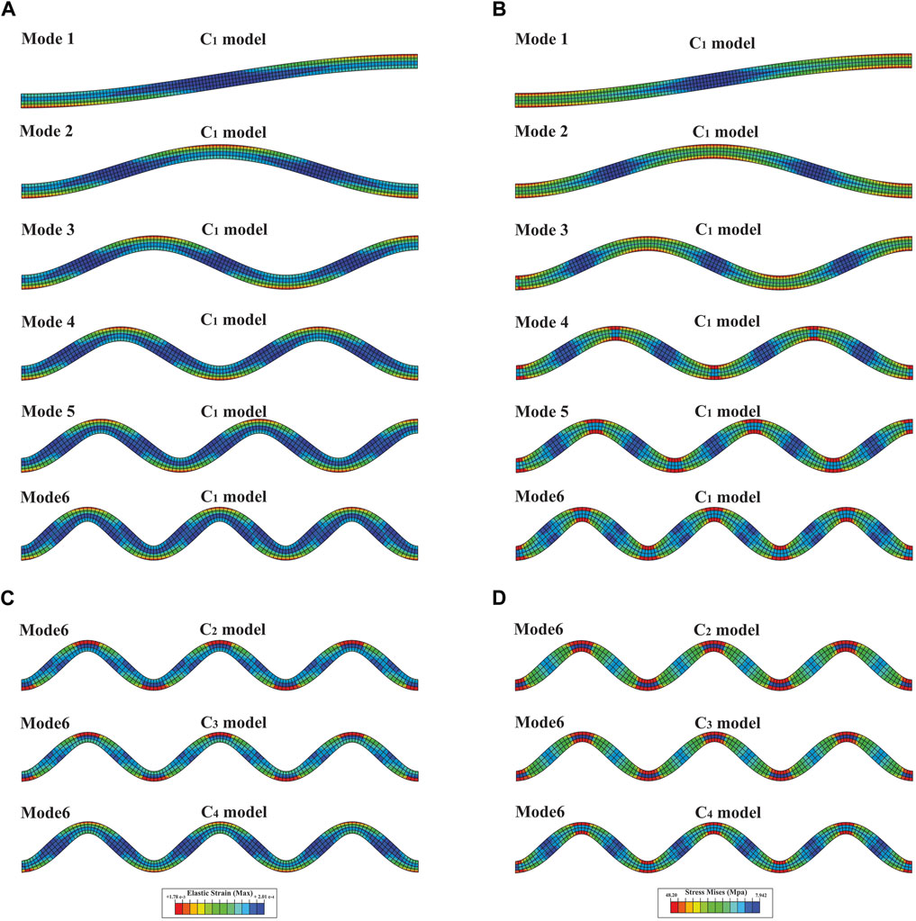
FIGURE 10. (A) distribution of elastic strain in the six buckling modes of the second layer, (B) distribution of Mises stress in the six buckling modes of the second layer, (C) distribution of elastic strain in the sixth mode of buckling for third layers (C2), fourth (C3) and fifth (C4), (D) distribution of Mises stress in the sixth mode of buckling for third layers (C2), fourth (C3) and fifth (C4).
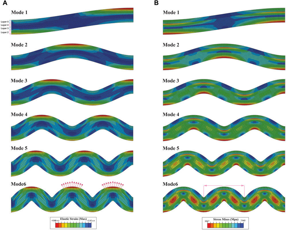
FIGURE 11. (A) distribution of elastic strain in the six buckling modes in a multi-layer (C5), (B) distribution of Mises stress in the six buckling modes in a multi-layer (C5). Layers one to five are shown in (A). The red arrows show the divergence of the boundary of the deformed squares in the two adjacent anticlines is equal. The pink arrow shows the half-wavelength from which the strain ellipse presented in Figure 13 was extracted.
Six buckling modes are shown for model C1 (Figures 10A, B), and only the sixth mode of buckling is shown for models C2 to C4 (Figures 10C, D). Each buckling mode produces 1/4 of the fold wavelength, so the fourth mode creates a full fold wavelength, and the sixth mode produces 1.5 of the fold wavelength. In all modes of all models, the elastic strain is maximum in the outer arch of the hinges zone in both anticlines and synclines (Figures 10A, B). Inversely, it decreases towards the centre of the limbs (Figures 10A, C). Mises stress is also maximum in the hinges zone (both anticline and synclines) and is minimum in limbs (Figures 10B, D). The created folds are symmetrical and uniform. However, the layers have been thinned in the hinge zones and thickened in the limb zones; these changes in thickness from the first to the sixth mode of buckling intensify (Figure 10). The C5 model shows the six modes of pure multi-layer buckling (non-slip). The elastic strain is localized in the outer arch of the hinges zone (Figure 11A). Mises stress is concentrated in the outer arc and the mid-layer inflection zone (Figure 11B).
As expected, non-slip is observed at the boundary of the layers of this model (Figure 11). In other words, the primary squares do not slide at the boundary of the layers, and folding is created by stretching the squares in the outer arc and their compression in the inner arc. As a result, the boundary of the squares creates an outward-diverging and inward-converging pattern. As shown in Figure 11A, the degree of their divergence in the outer arc of the adjacent anticlines is the same (Figure 11A).
3.5 Buckling and bending folding non-sliding (series D)
Series D consists of four models. In fact, they are multi-layer models that investigate the role of buckling and bending non-slip. The D1 and D2 models simulate bending at three-point and are elastic and elastic-plastic, respectively (Table 1; Figures 12A, C). Their boundary conditions are similar to Figure 2B. The F3 model simulates bending at four-point and has elastic rheology (Figure 12B). The D4 model also models multi-layer buckling non-slip (Figure 12D); its boundary conditions are shown in Figure 2E The difference between the D4 and C5 models, which simulate multi-layer buckling non-slip, is in the used equation. The C5 model uses the buckling relationship, and the D4 model uses the Hook relationship.
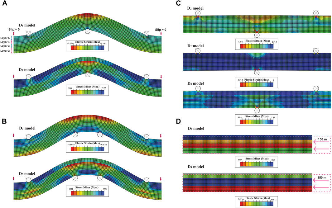
FIGURE 12. Distribution of elastic strain and Mises stress in non-slip multi-layer bending elastic models at three points (A) and four points (B, C) distribution of Mises stress and elastic and plastic strains in non-slip multi-layer bending elastic-plastic model at three points, and (D) distribution of elastic strain and Mises stress in non-slip multi-layer elastic buckling model.
A half-wavelength fold is created in D1 and D3 models, as in models A9 and A11 (Figures 7, 8, 12A, B). The elastic strain is localized in the hinge of the anticline (Figures 12A, B). The Mises stress is also localized in the hinge of the fourth layer (Figures 12A, B). No interlayer slip is observed throughout the two models. Bending occurs by extension of squares in the outer arc and compression in the inner arc. The squares’ boundary shows a weak divergence towards the outer arc (Figures 12A, B). The D2 elastic-plastic model stops after a few meters of displacement (Figure 12C); its stress and strain distribution are the same as the early stages of deformation of the D1 model (Figures 12A, C).
In the D4 model, no fold is created; only the thickness of the layers increases as in pure shear (Figure 12D). The elastic strain and the Mises stress are concentrated in the second and third layers, respectively (Figure 12D). In this model, no interlayer slip is observed. Only the primary squares are compressed in the displacement direction (Figure 12D).
4 Discussion
This research investigates the roles of sliding parallel to the layering (or along faults), buckling, and bending mechanisms in the formation of fault-related folds through the use of five series of 2D finite element models, encompassing a total of 29 models. Below, we compare our findings ith those of prior studies.
In series A, which simulates single-layer and multi-layer bending folding, the single-layer elastic-plastic models stop after applying a few meters of displacement (Figures 6B, D, F, H). In contrast, the multi-layer sliding model (A10) is run until the end of applied displacement (Figure 7B). This indicates the effect of sliding parallel to the layers in the elastic-plastic model of bending folding. The results are confirmed by stopping the multi-layer elastic-plastic no-slip model D2 that is presented to evaluate the results (Figure 12C). On the other hand, single-layer, and multi-layer elastic models are run until the end of the displacement (Figures 6A, C, E, H, 7A). Since the multi-layer elastic model has the interlayer slip (Figure 7A). We ran the D1 model to investigate the role of slip in elastic multi-layer bending (Figure 12A). This model is run until the end of the applied displacement (Figure 12A). Therefore, multi-layer bending elastic models are implemented in non-sliding and sliding conditions (Figures 7A, 12A). This issue shows the influence of rheology in bending. Therefore, the results of series A show that two parameters of rheology and sliding parallel to the layers are effective in bending folding.
Series B simulates buckling in single-layer and multi-layer. Any fold is not created in its single-layer models (elastic and elastic-plastic) and multi-layer elastic-elastic models (Figures 9A, B). Only its multi-layer elastic models can simulate buckling folding (Figures 9C, D). This issue shows the influence of rheology in buckling. To investigate the role of sliding parallel to the layer to buckling, the D4 model is run, a multi-layer elastic non-slipping model. As shown in Figure 12D, no fold is developed in this model. Hence, interlayer slip and rheology are controlling parameters buckling.
Earlier, Ramberg. (1964) investigated the effect of rheology characteristics on buckling. He found that competent materials responded better to buckling than incompetent materials. Buckling in competent materials creates a fold train, while incompetent materials only shorten and do not produce a fold train. This is consistent with the results of this research’s elastic and elastic-plastic models. This study’s multi-layer elastic buckling models (B4 and B5) generated a train of folds, while the multi-layer elastic-plastic buckling model (B3) only shortened and did not create any fold (Figures 9B–D). Therefore, sliding parallel to the layer and materials’ rheology characteristics play an essential role in the development of buckling folds.
4.1 Evaluation of strain ellipse of models
To compare the deformation pattern in this research’s models with each other and the models presented in previous works (Ramsay, 1967; Ramsay and Huber, 1987; Twiss and Moores, 1992), we manually extracted the strain ellipse of the multi-layer models of this research (Figure 13), based on the deformation of the primary squares, as shown in Figure 14 for the detachment fold model. The strain ellipse in the multi-layer bending-sliding models of the A series shows an all-over stretching in the entire model, which is increased in the contact surface of the rigid circular bodes with layers, even in the inner arc of the fold, the strain ellipse stretching is observed, and this tension in the bending model at four points is larger than the bending model at three points (Figure 13). While in the multi-layer non-slip bending models of series D, the strain ellipse is stretched in the outer arc and compressed in the inner arc (Figure 13). Of course, an amount of turbulence can be seen in the contact surface of the rigid circular bodes with layers (Figure 13).
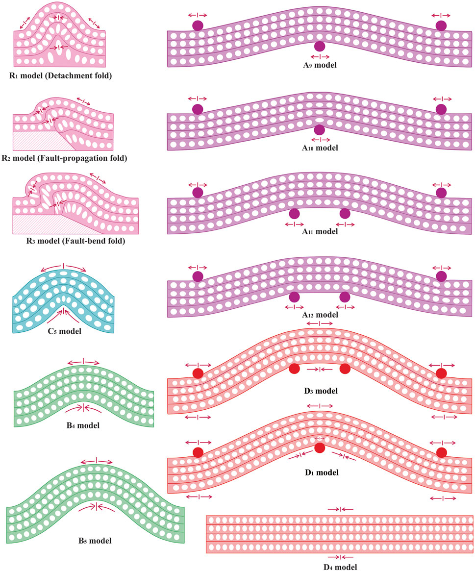
FIGURE 13. The strain ellipses of this study’s models are estimated based on the deformation of the initial squares. The half wavelengths from which these strain ellipses were extracted are marked with arrows in the previous figures.
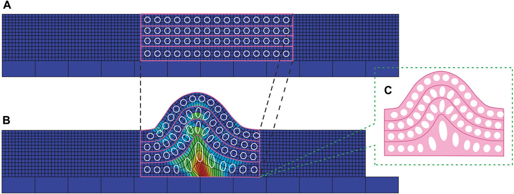
FIGURE 14. Overview of strain ellipsoid extraction from the deformation of square meshes in a detachment fold model, as follows: (A) Initial square mesh setup, (B) Progressive deformation illustrating strain ellipsoids, and (C) Enlarged detail of a fully developed strain ellipsoid within the fold apex.
In the multi-layer buckling models of series B (B4 and B5), the strain ellipse is stretched in the outer arc and compressed in the inner arc. In the non-slip buckling model of series D (D4), no folding occures, and like pure shear, the strain ellipse is compressed throughout the model (Figure 13).
In the buckling model of series C (C5) that use the buckling relationship, the strain ellipse is strongly stretched in the outer arc and strongly compressed in the inner arc (Figure 13). In other words, except for the A series in all multi-layer models, the strain ellipse is stretched in the outer arc and compressed in the inner arc. However, this issue is more significant in theC5 model (Figure 13). The strain ellipse of this model, is the same as the buckling multi-layer folding model presented by Ramsay. (1967) (Figures 13, 15A).
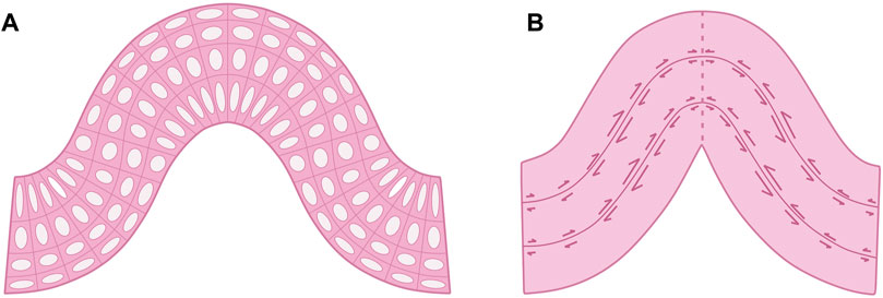
FIGURE 15. (A) Strain ellipse in the multi-layer buckling fold model (Ramsay, 1967), (B) slip changes in the flexural-slip fold model, and the size of the arrows shows the amount of slip (Twiss and Moores, 1992).
The strain ellipse in the detachment fold model is similar to (D5) buckling model (Figure 13). Except for the second layer of the detachment fold, which is deformed by the movement of material towards its centre and has not experienced buckling, The strain ellipse of the third to fifth layers is the same as the buckling model of series C (C5), whose strain ellipse is stretched in the outer arc and compressed in the inner arc. Perhaps it is reasonable to expect a bending mechanism from a detachment fold created by the upward pressure of its underlying layer, similar to bending sedimentary layers by the upward pressure of a magmatic mass. Contrary to expectation, the strain ellipse pattern in the upper layers of the detachment fold model is the same as the strain ellipse pattern in buckling (Figure 13). Of course, this is consistent with Butler et al.'s opinion (2020) about detachment folds. They believe that in addition to slipping parallel to the layer, the buckling mechanism also plays a critical role in developing detachment folds. The kinematic models presented for this folding ignore this issue.
In the fault-propagation and fault-bend fold models, the strain ellipses compress on the fault surface and forelimb while stretched on the back-limb (Figure 13). In fact, it seems that the presence of the fault has changed the place of compression from the centre of the fold to the fault tip and forelimb and the place of stretching from the crest to the back-limb (Figure 13). Therefore, in the geomechanical model of the fault-propagation and fault-bend folds, the effects of buckling can be observed in limbs of the folds. Of course, Butler et al. (2020) did not consider buckling influential in developing fault-bend folds. Still, the modelling results of this study showed that the buckling mechanism is also effective in the development of fault-propagation and fault-bend folds. However, its role is not as bold and significant as detachment folds.
In the multi-layer bending models at three-point of series A, and multi-layer buckling models of series B, the slip is zero at the model terminals and hinge surfaces, and it is maximized in the inflexion point (Figures 7, 9C, D). This is similar to the pattern of slip changes in the flexure slip folding mechanism presented by Twiss and Moores. (1992) (Figure 15B). While in the three fault-related fold models, the interlayer slip increases towards the model’s centre (hinge zone), inversely, the fault slip is reduced towards the hinge zone. In fact, in the model’s centre, the reduction of fault slip is compensated by the increase of interlayer slip, thickening of the layers, and buckling (Figures 3–5). Therefore, the main factor of deformation in the fault-related folds is the presence of the fault. The reduction of fault slip causes buckling in the hangingwall of the fault-propagation and fault-bend folds and the upper layers of the detachment layer in the detachment fold. Thus, variations in fault slip, slip parallel to the layer, and buckling are the controlling parameters of the development of fault-related folds.
On the other hand, the results of geomechanical models show that all three types of fault-related folds are created due to the reduction of fault, and their difference is in the place where the slip reaches zero. The slip reaches zero in the lower flat, or the detachment fault tip in the detachment folds. While in the fault-propagation and fault-bend folds at the ramp tip and upper flat, respectively, the slip reaches zero. Slip reduction in these places is compensated by increasing interlayer slip, increasing the thickness of layers, and buckling the upper layers.
5 Conclusion
In the presented research, the role of sliding mechanisms parallel to layering, buckling, and bending in the formation of fault-related folds were comprehensively investigated using five distinct 2D elastic and elastic-plastic finite element models. The key findings from our analysis are summarized as follows.
1) The rheological properties of the material and sliding parallel to layering are the dominant factors influencing bending in both single-layer and multi-layer models. Single-layer elastic-plastic models are not capable of folding via the bending mechanism. However, multi-layer elastic-plastic models that allow slip parallel to the layering do exhibit folding by bending. Conversely, where interlayer slip is absent (non-slip), these models do not exhibit any folding. Both single-layer and multi-layer elastic models fold by bending, regardless of whether sliding parallel to the layers is present or not.
2) Buckling is dependent on the rheological characteristics of the material and sliding parallel to the layer. The single-layer and multi-layer elastic-plastic models do not produce any fold by the buckling mechanism, Upside-down, only multi-layer elastic models are folded by the buckling mechanism at sliding conditions, and no folds are formed at no-slip conditions.
3) Variations in interlayer slip in bending and buckling models are the same as the pattern of slip changes in the flexure slip folding, where slip is absent at the hinge surfaces, then increases towards the limbs, and becomes maximum at the inflection points.
4) The strain ellipse and slip variation pattern in fault-related fold models show that sliding parallel to the layer and fault and buckling are two key mechanisms of fault-related folding. The reduction in fault slip creates all three types of fault-related folds; their difference is where this reduction occurs. The slip diminishes to zero at the detachment fault tip, the ramp tip, and the upper flat in the detachment, fault-propagation, and fault-bend folds, respectively.
Data availability statement
The original contributions presented in the study are included in the article/Supplementary material, further inquiries can be directed to the corresponding author.
Author contributions
AK-S: Data curation, Formal Analysis, Funding acquisition, Investigation, Methodology, Software, Visualization, Writing–original draft, Writing–review and editing. SA: Conceptualization, Methodology, Project administration, Supervision, Validation, Visualization, Writing–original draft, Writing–review and editing. MRG: Conceptualization, Methodology, Project administration, Supervision, Validation, Visualization, Writing–review and editing. MG: Methodology, Project administration, Validation, Visualization, Writing–review and editing. RD: Funding acquisition, Investigation, Resources, Writing–review and editing.
Funding
The author(s) declare that no financial support was received for the research, authorship, and/or publication of this article.
Conflict of interest
The authors declare that the research was conducted in the absence of any commercial or financial relationships that could be construed as a potential conflict of interest.
Publisher’s note
All claims expressed in this article are solely those of the authors and do not necessarily represent those of their affiliated organizations, or those of the publisher, the editors and the reviewers. Any product that may be evaluated in this article, or claim that may be made by its manufacturer, is not guaranteed or endorsed by the publisher.
References
Allmendinger, R. W. (1998). Inverse and forward numerical modeling of trishear fault propagation folds. Tectonics 17, 640–656. doi:10.1029/98tc01907
Barani, O. (2012). The effect of lower detachment zone on buckle folds geometry. J. Struct. Eng. Geotechnics 2 (1), 43–47.
Berger, P., and Johnson, A. M. (1980). First-order analysis of deformation of a thrust sheet moving over a ramp. Tectonophysics 70, 9–24. doi:10.1016/0040-1951(80)90276-0
Brandes, C., and Tanner, D. C. (2014). Fault-related folding: a review of kinematic models and their application. Earth-Science Rev. 138, 352–370. doi:10.1016/j.earscirev.2014.06.008
Butler, R. W. H., Bond, C. E., Cooper, M. A., and Watkins, H. (2020). Fold–thrust structures – where have all the buckles gone? Geol. Soc. Lond. Spec. Publ. 487, 21–44. doi:10.1144/sp487.7
Cardozo, N. (2005). Trishear modeling of fold bedding data along a topographic profile. J. Struct. Geol. 27, 495–502. doi:10.1016/j.jsg.2004.10.004
Cooke, M. L., and Pollard, D. D. (1997). Bedding-plane slip in initial stages of fault-related folding. J. Struct. Geol. 19, 567–581. doi:10.1016/S0191-8141(96)00097-1
Desai, Y. M., Eldho, T., and Shah, A. H. (2011). Finite element method with applications in engineering. India, Delhi: Pearson Education India.
Epard, J.-L., and Groshong, R. H. (1995). Kinematic model of detachment folding including limb rotation, fixed hinges and layer-parallel strain. Tectonophysics 247, 85–103. doi:10.1016/0040-1951(94)00266-c
Finch, E., Hardy, S., and Gawthorpe, R. (2003). Discrete element modelling of contractional fault-propagation folding above rigid basement fault blocks. J. Struct. Geol. 25, 515–528. doi:10.1016/s0191-8141(02)00053-6
Ghanbarian, M. A., and Derakhshani, R. (2022). The folds and faults kinematic association in Zagros. Sci. Rep. 12, 8350. doi:10.1038/s41598-022-12337-8
Ghanbarian, M. A., Yassaghi, A., and Derakhshani, R. (2021). Detecting a sinistral transpressional deformation belt in the Zagros. Geosciences 11 (6), 226. doi:10.3390/geosciences11060226
Hardy, S., and Finch, E. (2006). Discrete element modelling of the influence of cover strength on basement-involved fault-propagation folding. Tectonophysics 415, 225–238. doi:10.1016/j.tecto.2006.01.002
Hardy, S., and Poblet, J. (1995). The velocity description of deformation. Paper 2: sediment geometries associated with fault-bend and fault-propagation folds. Mar. Pet. Geol. 12, 165–176. doi:10.1016/0264-8172(95)92837-m
Hardy, S., Poblet, J., McClay, K., and Waltham, D. (1996). “Mathematical modelling of growth strata associated with fault-related fold structures,” in Modern developments in structural interpretation, validation and modeling (London: Geological Society), 265–282.
Homza, T. X., and Wallace, W. K. (1995). Geometric and kinematic models for detachment folds with fixed and variable detachment depths. J. Struct. Geol. 17, 575–588. doi:10.1016/0191-8141(94)00077-d
Homza, T. X., and Wallace, W. K. (1997). Detachment folds with fixed hinges and variable detachment depth, northeastern Brooks Range, Alaska. J. Struct. Geol. 19, 337–354. doi:10.1016/s0191-8141(96)00118-6
Hughes, A. N., Benesh, N. P., and Shaw, J. H. (2014). Factors that control the development of fault-bend versus fault-propagation folds: insights from mechanical models based on the discrete element method (DEM). J. Struct. Geol. 68, 121–141. doi:10.1016/j.jsg.2014.09.009
Hughes, A. N., and Shaw, J. H. (2015). Insights into the mechanics of fault-propagation folding styles. GSA Bull. 127 (11-12), 1752–1765. doi:10.1130/b31215.1
Johnson, A. M., and Berger, P. (1989). Kinematics of fault-bend folding. Eng. Geol. 27, 181–200. doi:10.1016/0013-7952(89)90033-1
Kent, W. N., and Dasgupta, U. (2004). Structural evolution in response to fold and thrust belt tectonics in northern Assam. A key to hydrocarbon exploration in the Jaipur anticline area. Mar. Pet. Geol. 21, 785–803. doi:10.1016/j.marpetgeo.2003.12.006
Khalifeh-Soltani, A., Alavi, A., Ghassemi, M. R., and Ganjiani, M. (2021a). Influence of mechanical parameters and overburden pressure on the mechanical evolution of fault propagation folds: insights from 2D finite-element elastic-plastic models applied to the Ayegan anticline, central Alborz. Geopersia 11 (1), 101–114. doi:10.22059/GEOPE.2020.297014.648530
Khalifeh-Soltani, A., Alavi, A., Ghassemi, M. R., and Ganjiani, M. (2021b). Geomechanical modelling of fault-propagation folds: estimating the influence of the internal friction angle and friction coefficient. Tectonophysics 815, 228992. doi:10.1016/j.tecto.2021.228992
Khalifeh-Soltani, A., Alavi, A., Ghassemi, M. R., and Ganjiani, M. (2021c). Influence of ramp geometry and orientation on fault propagation folding: insights from the 3D finite element method. J. Struct. Geol. 153, 104467. doi:10.1016/j.jsg.2021.104467
Khalifeh-Soltani, A., Alavi, S. A., Ghassemi, M. R., and Derakhshani, R. (2023a). Stress and strain evolution in fault-related folds: insights from 2D geomechanical modelling. Front. Earth Sci. 11, 1249446. doi:10.3389/feart.2023.1249446
Khalifeh-Soltani, A., Ghassemi, M. R., Alavi, A., and Ganjiani, M. (2023b). Parameters controlling the geometry of detachment and fault-bend folds: insights from 3D finite-element models applied to the Ahwaz anticline in the Dezful Embayment, SW Iran. Petroleum Geol. 46 (2), 157–190. doi:10.1111/jpg.12834
Li, Y., Hou, G., Hari, K. R., Neng, Y., Lei, G., Tang, Y., et al. (2018). The model of fracture development in the faulted folds: the role of folding and faulting. Mar. Petroleum Geol. 89 (2), 243–251. doi:10.1016/j.marpetgeo.2017.05.025
Li, Z., Chen, W., Jia, D., Sun, C., Zheng, W., Zhang, P., et al. (2019). The effects of fault geometry and kinematic parameters on 3D fold morphology: insights from 3D geometric models and comparison with the Dushanzi anticline, China. Tectonics 39, e2019TC005713. doi:10.1029/2019TC005713
Maerten, F., Maerten, L., and Pollard, D. D. (2014). iBem3D, a three-dimensional iterative boundary element method using angular dislocations for modeling geologic structures. Comput. Geosciences 72, 1–17. doi:10.1016/j.cageo.2014.06.007
McClay, K. (2011). “Introduction to thrust fault-related folding,” in Thrust-fault related folding. Editors K. McClay, J. H. Shaw, and J. Suppe (AAPG Mem), 94, 1–19. doi:10.1306/13251330M9450
McClay, K. R. (1995). “The geometries and kinematics of inverted fault systems: a review of analogue model studies,” in Basin inversion. Editors J. G. Buchanan, and P. G. Buchanan (London: Geological Society), 88, 97–118.
Mitra, S. (1990). Fault-propagation folds: geometry, kinematic evolution, and hydrocarbon traps. AAPG Bull. 74, 921–945. doi:10.1306/0c9b23cb-1710-11d7-8645000102c1865d
Mitra, S. (1993). Geometry and kinematic evolution of inversion structures. AAPG Bull. 77, 1159–1191. doi:10.1306/bdff8e2a-1718-11d7-8645000102c1865d
Morley, C. K., King, R., Hillis, R., Tingay, M., and Backe, G. (2011). Deepwater fold and thrust belt classification, tectonics, structure and hydrocarbon prospectivity: a review. Earth Sci. Rev. 104, 41–91. doi:10.1016/j.earscirev.2010.09.010
Peacock, D. C. P., Knipe, R. J., and Sanderson, D. J. (2000). Glossary of normal faults. J. Struct. Geol. 22, 291–305. doi:10.1016/s0191-8141(00)80102-9
Poblet, J., and Hardy, S. (1995). Reverse modelling of detachment folds: application to the Pica de1 Aguila anticline in the South Central Pyrenees (Spain). J. Struct. Geol. 17, 1707–1724. doi:10.1016/0191-8141(95)00059-m
Poblet, J., and McClay, K. (1996). Geometry and kinematics of single-layer detachment folds. AAPG Bull. 80, 1085–1109. doi:10.1306/64ed8ca0-1724-11d7-8645000102c1865d
Poblet, J., McClay, K., Storti, F., and Muñoz, J. A. (1997). Geometries of syntectonic sediments associated with single-layer detachment folds. J. Struct. Geol. 19, 369–381. doi:10.1016/s0191-8141(96)00113-7
Ramberg, H. (1964). Selective buckling of composite layers with contrasted rheological properties, a theory for simultaneous formation of several orders of folds. Tectonophysics 1 (4), 307–341. doi:10.1016/0040-1951(64)90020-4
Ramsay, J. G., and Huber, M. I. (1987). The techniques of modern structural Geology, volume 2: folds and fractures. London: Academic Press.
Rashidi, A., Shafieibafti, S., Nemati, M., Ezati, M., Gholami, E., Mosavi, S. M., et al. (2023). Flexural-slip folding in buckling phases of orogenic belts: insight into the tectonic evolution of fault splays in the East Iran orogen. Front. Earth Sci. 11, 1169667. doi:10.3389/feart.2023.1169667
Smart, K. J., Ferrill, D. A., Morris, A. P., and McGinnis, R. N. (2012). Geomechanical modeling of stress and strain evolution during contractional fault-related folding. Tectonophysics 576–577, 171–196. doi:10.1016/j.tecto.2012.05.024
Suppe, J. (1983). Geometry and kinematics of fault-bend folding. Am. J. Sci. 283, 684–721. doi:10.2475/ajs.283.7.684
Suppe, J., and Medwedeff, D. A. (1990). Geometry and kinematics of fault-propagation folding. Eclogae Geol. Helv. 83, 409–454.
Keywords: fault-related folding, 2D finite-element modelling, sliding, buckling, bending
Citation: Khalifeh-Soltani A, Alavi SA, Ghassemi MR, Ganjiani M and Derakhshani R (2023) Elucidating fault-related fold mechanics: a 2D finite element analysis of bending, slip, and buckling mechanisms. Front. Earth Sci. 11:1295898. doi: 10.3389/feart.2023.1295898
Received: 17 September 2023; Accepted: 16 November 2023;
Published: 04 December 2023.
Edited by:
Zhong-Hai Li, University of Chinese Academy of Sciences, ChinaReviewed by:
Yujun Sun, Chinese Academy of Geological Sciences, ChinaZhen Zhang, Institute of Geology, China Earthquake Administration, China
Copyright © 2023 Khalifeh-Soltani, Alavi, Ghassemi, Ganjiani and Derakhshani. This is an open-access article distributed under the terms of the Creative Commons Attribution License (CC BY). The use, distribution or reproduction in other forums is permitted, provided the original author(s) and the copyright owner(s) are credited and that the original publication in this journal is cited, in accordance with accepted academic practice. No use, distribution or reproduction is permitted which does not comply with these terms.
*Correspondence: Reza Derakhshani, r.derakhshani@uu.nl