Study on the Overburden Failure Law of High-Intensity Mining in Gully Areas With Exposed Bedrock
 Tan Yi1,2
  Xu Han1
  Yan Weitao2* Guo Wenbing1,2 Bai Erhu1,2 Qi Tingye3 Yin Dawei4 Hao Bingyuan3
  Cheng Hao1 Shao Minghao1
- 1School of Energy Science and Engineering, Henan Polytechnic University, Jiaozuo, China
- 2State Collaborative Innovation Center of Coal Work Safety and Clean-efficiency Utilization, Henan Polytechnic University, Jiaozuo, China
- 3College of Mining Engineering, Taiyuan University of Technology, Taiyuan, China
- 4College of Energy and Mining Engineering, Shandong University of Science and Technology, Qingdao, China
Most hilly areas are dotted with gullies, some of which contain plenty of water, especially in rainy seasons. Once surface water penetrates the underground working face, it will lead to an increased water inflow of the working face. Even worse, it may induce water and sand burst accidents. To prevent geological disasters such as water and sand burst and ensure the safe production in coal mines, it is necessary to reveal the development law of “two zones” in the overburden caused by shallow-seam fully mechanized top coal caving high-intensity mining in hilly areas with exposed bedrock and timely grasp the communication between the water-flowing fractured zone (WFFZ) and the water in surface gullies. In this study, the working face P2 of the exposed bedrock surface in the Coal Mine DN is taken as the research object. First, the characteristics of overburden movement and the law of exposed bedrock surface movement in areas with exposed bedrock were investigated through similar simulation. Meanwhile, the temporal–spatial evolution of overburden movement caused by shallow-seam fully mechanized top coal caving high-intensity mining was clarified, and the mode of overburden movement was revealed. Moreover, the reason why the water inflow of the underground working face increases suddenly was theoretically explained. The following conclusions were drawn: Under shallow-seam fully mechanized top coal caving high-intensity mining, the WFFZ of the working face P2 is directly connected to the exposed bedrock surface, and the movement of the overburden is subject to the typical “two-zone” mode. The development height of the WFFZ is greater than the value in the traditional “three-zone” mode calculated according to the empirical formulas. The ratio of the WFFZ height to the mining thickness is 43.75. Under the “two-zone” mode, a water-flowing channel exists in the overburden near the open-off cut and the stopping line. When the surface water source is in the right position, the water inflow of the underground working face will increase suddenly.
Introduction
Underground coal mining often induces large-scale damage to overburden and surface movement, further accelerating the occurrence of mine geological disasters such as water and sand burst under the condition of shallow-seam mining (Kratzsch, 1983; Gray, 1990). The key to preventing water and sand burst is to reveal the height of “two zones” (i.e., the caved zone and the fractured zone) in the overburden (Sun et al., 2011; Author Anonymous, 2014). At present, the prediction of the height of the “two zones” in China is mainly based on the calculation formulas concluded with reference to the conventional mining and fully mechanized mining faces in the 1950s and 1990s. The formulas are presented in the Code for coal pillar preservation and pressed coal mining of buildings, water bodies, railways, and main tunnels (hereinafter referred to as the Code) (State Administration of s, 2017). With the popularization of fully mechanized top coal caving mining and one-time full thickness mining under a large mining height, the mining height and advancing speed of the working face, together with the height of “two zones,” have increased significantly (Yonghua and Renchang, 2003; Yanchun et al., 2011). Relevant scholars have found the limitations of the calculation formulas for the height of “two zones” in the Code and conducted studies on the height of “two zones” under large mining height, thin bedrock, small buried depth, and fully mechanized top coal caving mining (Minggao and Xiexing, 1995; Baobin and Xiaolei, 2013; Jianjun et al., 2008; Xiaoqian and Zhenquan, 2015; Duan et al., 2011; Qingxian et al., 2013; Yiqiong, 2008), following which some conclusions have been put forward.
However, studies on the height of “two zones” in the overburden of fully mechanized top coal caving high-intensity mining working faces in the shallow-seam gully areas remain insufficient. Such studies are of prime importance for ensuring the production safety of the mines, especially for those water-containing gully areas in the overburden. Therefore, research on the structural characteristics of overburden under fully mechanized top coal caving mining in the shallow-seam gully areas with exposed bedrock, as well as the development height of “two zones” in the flowing fractured zone, is of great significance for improving the basic theory and guiding the field production.
The key to studying the height of “two zones” is to reveal the mechanism of overburden migration. Currently, studies on the mechanism of overburden migration in shallow-seam high-intensity mining working faces mainly focus on the displacement migration mode of the overburden (Weitao et al., 2021; Yunjiang et al., 2021), the distribution law of overburden failure (Rezaei et al., 2015; Sasaoka et al., 2015; Thongprapha et al., 2015; Vervoort, 2016; Enke et al., 2020), and the conduction relationship concerning overburden failure (Zhiguo et al., 2019; Xiaoshuai et al., 2021; Zhenkang et al., 2021).
In this study, the working face P2 in the Coal Mine DN, which is located in hilly areas with an exposed bedrock surface and is mined by the method of shallow-seam fully mechanized top coal caving, is taken as the research object. First, the geological conditions of fully mechanized top coal caving in hilly areas with exposed bedrock were analyzed, and the structural characteristics of the roof overburden in the working face were experimentally determined. Besides, the overburden fractures and the height of “two zones” in the working face were investigated by means of experiments and theoretical analysis. Furthermore, the height of “two zones” in the overburden was explored based on the changes of mine water inflow. Finally, the on-site measured height and the results obtained from the empirical formulas were compared. The research results obtained are crucial.
Project Background
Surface Profile
The Coal Mine DN has a designed production scale of 4.0 Mt/a. The working face P2, which is 220 m in width and 1,138 m in the designed mining length, is the second working face in the first panel. The coal seam 3#, whose ground elevation ranges from +658 m to +780 m and floor height ranges from +509 m to +472 m, is the mining coal seam. The working face P1 (450 m in the north) and the unexploited region lie on the west of the working face P2, while the working face P3 (unexploited) lies on the east of it.
In terms of its surface landform, the working face features unique loess-covered low mountains and an exposed bedrock surface. Three gullies (numbered 1, 2, and 3 from south to north) where water flows all year round with a total volume of 15–20 tons/h (larger in the rainy season) exist in the working face (Table 1). The water mainly comes from descending springs in the weathered crust (Figure 1).
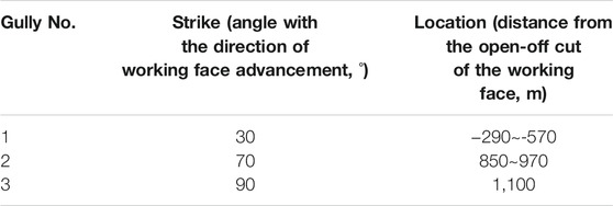
TABLE 1. Gully distribution.
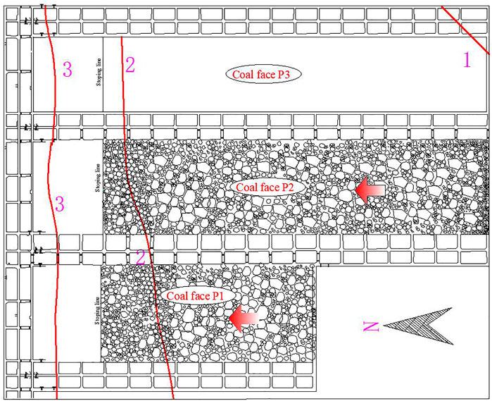
FIGURE 1. Gullies of working faces P2 and P3.
Mining Technical Parameters
The working face adopts longwall fully mechanized top coal caving, and the roof is managed by the all caving method. The relevant mining technical parameters are listed in Table 2.
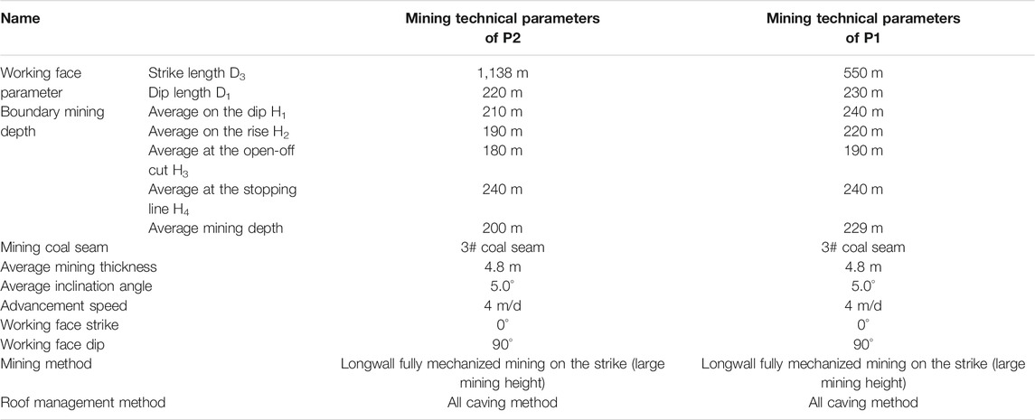
TABLE 2. Mining technical parameters of the fully mechanized caving faces P2 and P1.
Measured Height of “Two Zones” in the Overburden
Calculation Based on Empirical and Literature Formulas
According to the relevant data of the mines, the coal seam 3# of the working face P2 belongs to the Taiyuan Formation of the upper carboniferous system and has a thickness of 4.8 m, a stable morphology, and a complex structure. In addition, the drilling histogram near the working face reveals that the lithology of the overburden of the working face P2 is comprehensively evaluated as medium-hard (Figure 2).
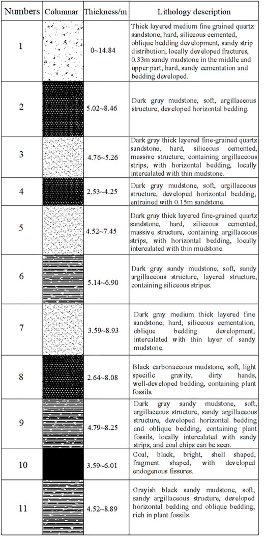
FIGURE 2. Drilling histogram of the working face P2.
Based on a large number of measured data of the water-flowing fractured zone (WFFZ) under the condition of top coal caving mining, Chinese scholars, after regression, have obtained empirical formulas for the height of the WFFZ applicable to top coal caving mining. Among them, the empirical and literature formulas of the height of the WFFZ under top coal caving mining of gently sloped medium-hard overburden thick coal seam are as follows.
The formula proposed by Liu is
The formula proposed by Teng is
The formula proposed by Xu is
The formula proposed by Ding is
According to the above formulas, the selected points for calculating the height of the WFFZ in the working face P2 are 56.21–77.05 m, 106 m, 47.57–70.55 m, and 42.22–68.74 m, respectively. The height of the WFFZ in the working face P2 under thick-seam top coal caving mining ranges from 42.22 to 106 m, and the ratio of the WFFZ height to the mining thickness is 8.80–22.08.
Measurement and Analysis of WFFZ
In the light of the theory of mining subsidence, the judgment formula for sufficient mining of the working face is
When c is greater than or equal to 1.2–1.4, the working face is mined sufficiently, and the vertical and horizontal ranges of overburden failure reach the maximum. When c is smaller than 1.2–1.4, the working face is mined insufficiently, and the damage range of overburden is not fully developed. The mining of the P1 working face was completed in early February 2006, with a dip of 230 m, a strike of 550 m, and a mining depth of 229 m:
It can be seen from the above formula that the strike of the P1 working face is mined sufficiently, while the dip is mined insufficiently. That is, the overburden failure of the working face is not fully developed.
According to the hydrological observation data, there are three sources of water in the overburden, that is, the earth surface, the loose layer, and the bedrock. Relatively less water comes from the loose layer and the bedrock. The bedrock in the overburden and the aquifer of loose layer have been connected to the working face after the recovery of the working face P1, but the water inflow is merely 6 m3/h during the recovery.
The working face P2 is close to the working face P1, and they share similar hydrogeological and mining conditions. After the working face P2 starts to be recovered following the working face P1, the dip of the working face P2 can be sufficiently mined, and the longitudinal failure of the overburden can reach the maximum range. At this time, if the longitudinal failure of the overburden reaches the surface, the surface water will flow into the working face, increasing the water inflow of the working face. Therefore, the surface cracks and changes of water inflow of the working face P2 can tell whether the WFFZ in the overburden has reached the surface.
In view of the above situation, observation stations shall be established on the surface for crack observation, and monitoring points shall be established underground for water inflow monitoring. The specific layout scheme is as follows:
① The three gullies above the working face are mainly composed of descending springs in the weathered crust. The location of the gullies and observation line is shown in Figure 3. An observation line A with 46 observation stations (spacing 20 m) is arranged along the strike of the working face. Among the observation stations, A1–A6, A17–A19, and A28–A32 are on the exposed bedrock surface and the others are on the loess-covered surface. Besides, an observation line B with 18 observation stations (spacing 20 m) is arranged along the No. 2 gully, and the whole line is on the exposed bedrock surface.
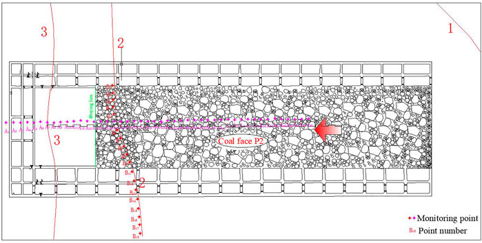
FIGURE 3. Location of gully and observation lines.
② During the recovery of the working face P2, the water inflow of the working face is monitored underground six times a day. The relevant data on the hourly water inflow are listed in Table 3.
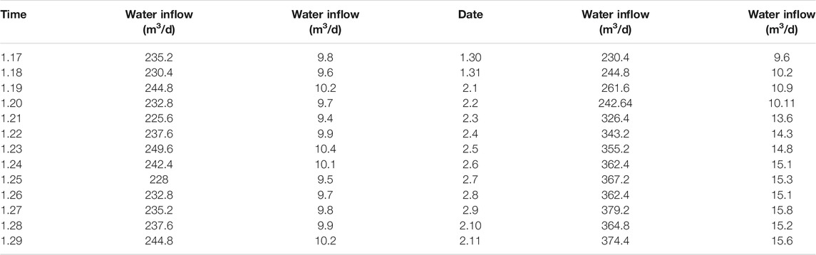
TABLE 3. Water inflow of the fully mechanized caving face P2.
As illustrated in Figure 4, during the recovery, the water inflow of the working face P2 was around 10 m3/h. On 3 February 2007, the water inflow increased abruptly to 13.6 m3/h and then was maintained at about 15 m3/h. Taking the mining surface overburden during the recovery (Figure 5) into consideration, at this time, penetrating cracks had been found at the A17 observation station of the No. 2 gully. Therefore, it is determined that the WFFZ in the overburden had developed to the exposed bedrock surface, with the maximum WFFZ height and the ratio of the WFFZ height to the mining thickness being 226 m and 47.08, respectively. The ratio calculated by the empirical formulas mentioned above is only 8.80–22.08, which is far smaller than the measured value.
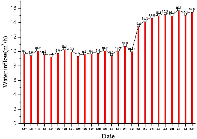
FIGURE 4. Change of water inflow in the working face P2.
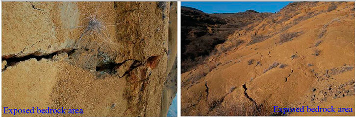
FIGURE 5. Surface rock cracks above the working face.
Experiments and Results
Experimental Design
To simulate WFFZ development under high-intensity mining, a physical simulation experiment was performed according to the mine geological and mining data. To simplify the experimental conditions, the surface is simplified to horizontal terrain in this paper. According to the characteristics of overburden and simulated materials, the simulated geometric similarity ratio is 1:200, the unit weight ratio is 0.6, the stress ratio is 0.004, and the time ratio is 0.082. Gypsum, calcium carbonate, and fine sand are used as raw materials for the production of simulation materials. After each layer is laid, the mica powder is evenly spread as the joint surface between rock layers. The finished model is shown in Figure 6.
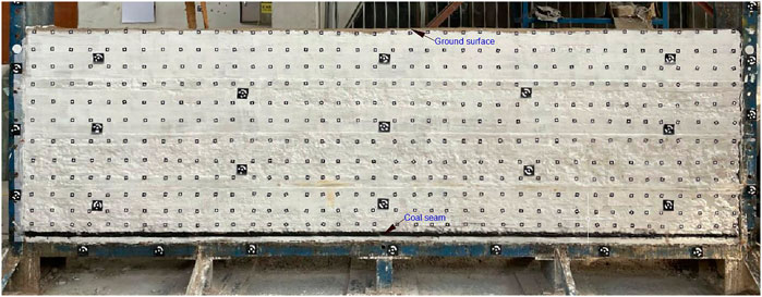
FIGURE 6. Physical model experiment.
Overburden Failure Law
After the model was made and dried for 1 week, the simulated excavation was carried out by means of one-time full thickness mining in sections. The rock stratum failure in each excavation stage is shown in Figure 7.
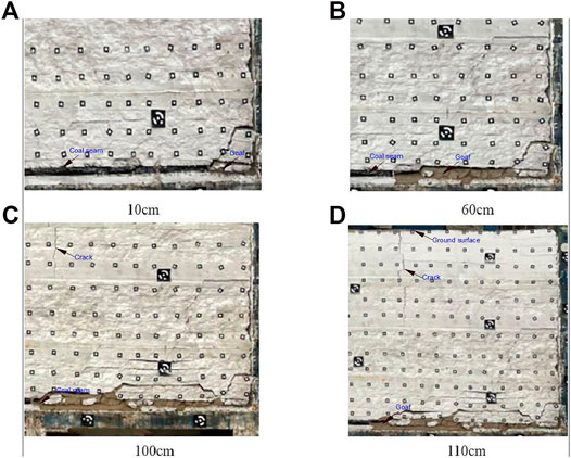
FIGURE 7. Breakage states of rock strata of the physical model in different periods.
When the working face is excavated for 15 cm, the roof of the coal seam falls and accumulates in blocks in the goaf (Figure 7A). When the working face is excavated for 60–100 cm, the immediate roof falls. As the excavation proceeds, the roof continues to collapse, forming a trapezoidal collapse space above the goaf (Figures 7B,C). When the working face is excavated for 110 cm, all overburden bedrock in the coal seam collapses, and surface cracks run through the working face (Figure 7D).
According to the pressure arch theory, a pressure arch exists on the periphery of the collapse space. In the initial stage of excavation, the height of the rock arch increases continuously, and the roof repeats the cyclic process of “arch formation and arch breakage.” In this process, the rock and soil mass above the rock arch only undergo bending compression, and the overburden balance structure belongs to a “rock arch.” When the excavation reaches 110 cm, the thickness of the overburden becomes smaller than the critical arch height of the rock arch. Consequently, the rock arch is broken, and the overburden movement directly enters the “no arch” stage. In addition, the cracks connect the surface and the working face, and the WFFZ directly reaches the surface. Under such conditions, the mining balance structure of rock and soil mass develops from “rock arch” to “no arch.”
Discussion
High-intensity mining is characterized by shallow seam, large mining thickness, and high advancing speed. Under high-intensity mining, the overburden and the surface are seriously damaged, which mainly goes through the following three periods.
Period 1. When the failure height of the overburden is smaller than its thickness:
In this stage, as the working face continues to advance, the overburden first bends and then breaks when the maximum tensile intensity in the middle of the rock stratum is exceeded. The collapse degree of the roof mainly depends on the thickness and lithology of the overburden as well as the mining method. With the continuous expansion of the goaf area, the lower strata of the roof will fracture and collapse when their limit span is reached. When the collapsed gangue fails to completely fill the goaf, the overburden becomes suspended, adding its own weight to the surrounding rock of the goaf via beams and plates. As a result, a pressure arch is formed in the surrounding rock. As the horizontal and vertical failures of the overburden expand, the span and height of the pressure arch are also increasing. In this stage, the failure height of the overburden is smaller than its thickness (Figure 8A).
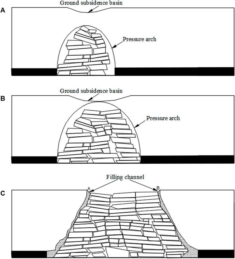
FIGURE 8. Failure mode of strata in the two zone mode.
Period 2. When the failure height of the overburden equals its thickness:
At this time, the overburden is in a critical state of failure. The height of the pressure arch in the overburden and the failure height of the overburden both reach the maximum. The overburden is damaged in its full thickness, and the WFFZ reaches the surface (Figure 8B).
Period 3. After the failure height of the overburden equals its thickness:
As the working face continues to advance, the overburden failure only develops horizontally. That is, the failure height of the overburden no longer changes, but the horizontal failure range of the overburden expands with the advancement of the working face (Figure 8C).
The above stages can be divided into two states, i.e., “rock arch” and “no arch,” according to the existence state of a pressure arch in the overburden.
State 1: “Rock Arch”
In this state, the rock strata in the pressure arch are broken seriously and are in the pressure release area. The weight of the rock strata outside the pressure arch is transmitted to the foot of the pressure arch. As the working face advances, the height and dimension of the pressure arch are increasing, and the arch foot on the advancing side of the working face is also moving forward. The height of the pressure arch reaches the limit if it equals the thickness of the overburden. This state corresponds to Periods 1 and 2 described above.
State 2: “No Arch”
In this state, as the working face continuously advances, the pressure arch breaks, and hence, no pressure arch exists in the overburden. At this time, a conduction channel, which directly connects to Positions A and B on the surface, occurs between the continuous moving rock stratum and the broken rock stratum above the open-off cut and the advancing position of the working face. The two positions can be determined through the following methods:
where
When there are water-containing gullies near Positions A and B, the water will flow into the working face, hence increasing its water inflow.
Actual measurement reveals that the No. 2 gully is 168–288 m away from the stopping line where the mining depth is about 240 m. The calculated distance between Position B and the stopping line is
It can be concluded that the No. 2 gully is located near Position B of the working face P2. After the working face P2 starts to be recovered following the working face P1, the dip can reach the state of sufficient mining, and the longitudinal failure of the overburden can reach the maximum range. The WFFZ reaches the surface, forming water-flowing channels on both sides of the stopping line and open-off cut. As a result, the water inflow in the underground working face increases.
Traditionally, “three zones” (i.e., caved zone, fractured zone, and sagging zone) exist in the overburden of the working face (Figure 9). The prediction formulas for the height of the WFFZ described in Project Background are based on the “three-zone” mode. After the recovery of the working face P2, only the caved zone and fractured zone remain in the overburden of the working face, which belongs to a typical “two-zone” mode. The prediction formula of the WFFZ based on the traditional “three-zone” mode is not suitable for the “two-zone” mode, which explains the large deviation of predicted values through the formulas.
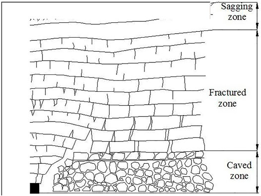
FIGURE 9. Longitudinal distribution of three zones in the overburden in the three zone mode.
Conclusion
1) The overburden of the working faces P2 and P1 moves under the “two-zone” mode. The height prediction formula of the WFFZ based on the traditional “three-zone” mode is inapplicable to the “two-zone” high-intensity mining mode, which results in the relatively small calculated result. After the working faces P2 and P1 were recovered, both the strike and the dip reach the state of sufficient mining, and the height of the WFFZ is the most fully developed.
2) Under the “two-zone” mode, a conduction channel that directly connects to the surface exists between the continuous moving rock stratum and the broken rock stratum above the open-off cut and the advancing position of the working face. If there is a water source near the surface of the channel, the water will flow into the working face, causing an increase in the water inflow of the underground working face.
Data Availability Statement
The raw data supporting the conclusion of this article will be made available by the authors, without undue reservation.
Author Contributions
TY conceptualized the research idea, wrote the original draft, and was involved in funding acquisition. YW performed the methodology, ran the software, supervised the project, and reviewed and edited the paper. XH and GW validated the data. BE was involved in formal analysis. YD and HB investigated the data. QT obtained the resources. TY and XH curated the data. GW was involved in data visualization. XH was responsible for project administration. All authors have read and agreed to the published version of the manuscript.
Funding
This work was financially supported by the National Natural Science Foundation of China (52174108, 51974105, and 52104127), Program for Outstanding Young Talent Projects of Henan Province (222300420045), Program for Science and Technology Innovation Talents in Universities of Henan Province (21HASTIT024), Open Fund of State Key Laboratory of Water Resource Protection and Utilization in Coal Mining (GJNY-18-73.16), State Key Laboratory of Coal Resources in Western China (SKLCRKF1912), and Scientific and Technological Innovation Research Team of Henan Polytechnic University (T2021-5).
Conflict of Interest
The authors declare that the research was conducted in the absence of any commercial or financial relationships that could be construed as a potential conflict of interest.
Publisher’s Note
All claims expressed in this article are solely those of the authors and do not necessarily represent those of their affiliated organizations, or those of the publisher, the editors, and the reviewers. Any product that may be evaluated in this article, or claim that may be made by its manufacturer, is not guaranteed or endorsed by the publisher.
References
Dingtao, C., and Wenping, L. (2014). Estimation Method for Height of Fratured Zone with in Coal Mining Area. Chin. J. Geol. Hazard Control. 1, 63–69.
Baobin, G., and Xiaolei, Z. M. W. (2013). Dynamic Development Characteristics of Two Zones of Overburden Strata under Conditions of Compound Roof Highly Gassy and Thick Coal Seam in Full-Mechanized Top Cole Caving Faces. Chin. J. Rock Mech. Eng. 31, 3444–3451.
Duan, H, Zhu, S, and Cao, S, Zhang, M, (2011). Study on Method to Set Safety Coal and Rock Pillar for Full Mechanized Top Coal Caving Mining under Water Body. Coal Sci. Tech. 11, 1–4.
Enke, H., Qiang, W., Zhenni, Y., Wei, C., and Jiangbo, W. (2020). Height Prediction of Water-Flowing Fracture Zone with a Genetic-Algorithm Support-Vector-Machine Method. Int. J. Coal Sci. Tech. 7, 740–751.
Gray, R. E. (1990). Mining Subsidence ? Past, Present, Future. Int. J. Mining Geol. Eng. 8, 400–408. doi:10.1007/bf00920651
Jianjun, C., Qihua, M., and Yitai, W. (2008). Study of Wide Strip Mining Based on Spatial Structure Principle of Overlying Strata. Coal Sci. Tech. 1, 68–72.
Minggao, Q., and Xiexing, M. (1995). Theoretical Analysis of the Structural Form and Stability of Overlying Strata in Long Wang Mining. Chin. J. Rock Mech. Eng. 2, 97–106.
Qingxian, S., Yi, M, and Xinliang, Y. (2013). Study on “Two Zones” Height of Overlying of Fully-Mechanized Technology with High Mining Height at Hongliu Coal Mine. J. China Coal Soc. 38, 283–286.
Rezaei, M., Hossaini, M. F., and Majdi, A. (2015). A Time-independent Energy Model to Determine the Height of Destressed Zone above the Mined Panel in Longwall Coal Mining. Tunnelling Underground Space Tech. 47, 81–92. doi:10.1016/j.tust.2015.01.001
Sasaoka, T., Takamoto, H., Shimada, H., Oya, J., Hamanaka, A., and Matsui, K. (2015). Surface Subsidence Due to Underground Mining Operation under Weak Geological Condition in Indonesia. J. Rock Mech. Geotechnical Eng. 7, 337–344. doi:10.1016/j.jrmge.2015.01.007
State Administration of safety, State Administration of coal mine safety, state energy administration, state railway administration (2017). Buildings Water, Railways and Main Well Lane of Coal Pillar and Mining Regulations. Beijing: China Coal Industry Publishing Huose.
Sun, Y, and Xu, Z, Dong, Q, (2011). Monitoring and Simulation Research on Devel Opment of Water Flowing Fractures for Coal Mining under Xiaolangdi Reservoir. Chin. J. Rock Mech. Eng. 31, 3444–3451.
Thongprapha, T., Fuenkajorn, K., and Daemen, J. J. K. (2015). Study of Surface Subsidence above an Underground Opening Using a Trap Door Apparatus. Tunnelling Underground Space Tech. 46, 94–103. doi:10.1016/j.tust.2014.11.007
Vervoort, A. (2016). Surface Movement above an Underground Coal Longwall Mine after Closure. Nat. Hazards Earth Syst. Sci. 16, 2107–2121. doi:10.5194/nhess-16-2107-2016
Weitao, Y., Junjie, C., and Tan, y. (2021), Theoretical Analysis of Mining Induced Overburden Subsidence Boundary with the Horizontal Coal Seam Mining. Adv. civil Eng. 6657738.
Xiaoqian, S., and Zhenquan, W. Z. J. (2015). Height Prediction of the “Two Zones” in Shallow Coal Seam by Slicing Ming. Minging Res. Dev. 2, 69–72.
Xiaoshuai, L., Kun, P., Jun, P., and Di, H. (2021). Experimental Investigation of Cyclic Wetting-Drying Effect on Mechanical Behavior of a Medium-Grained sandstone. Eng. Geologyg 293, 106335.
Yanchun, X., Juncheng, L., and Shiqi, L. (2011). Calculation Formula of “Two-zone”height Overlying Strata and its Adaptability Analysis. Coal Mining Tech. 2, 4–7.
Yiqiong, X. (2008). Research on Movement and Evolution Law of Breaking of Overlying Strata in Shallow Coal Seam with a Thin Bedrock. Rock Soil Mech. 2, 512–516.
Yonghua, K., and Renchang, J. (2003). Actuality and Developing Trend of Long wall Top Coal Caving Mining under Water. Coal Mining Tech. 1, 15–18.
Yunjiang, Sun., Jianping, Zuo., and Karakus, Murat. (2021). A New Theoretical Method to Predict Strata Movement and Surface Subsidence Due to Inclined Coal Seam Mining,. Rock Mech. Rock Eng. 54, 2723–2740.
Zhenkang, Wang., Wenping, Li., Qiqing, Wang., Yanbo, Hu., and Jiafa, Du. (2021). Monitoring the Dynamic Response of the Overlying Rock–Soil Composite Structure to Underground Mining Using BOTDR and FBG Sensing Technologies. Rock Mech. Rock Eng. 54, 5095–5116.
Keywords: water-containing gullies, exposed bedrock, shallow thick coal seam, fully mechanized top coal caving mining, water-flowing fractured zone
Citation: Yi T, Han X, Weitao Y, Wenbing G, Erhu B, Tingye Q, Dawei Y, Bingyuan H, Hao C and Minghao S (2022) Study on the Overburden Failure Law of High-Intensity Mining in Gully Areas With Exposed Bedrock. Front. Earth Sci. 10:833384. doi: 10.3389/feart.2022.833384
Received: 11 December 2021; Accepted: 14 February 2022;
Published: 03 March 2022.
Edited by:
Wei Liu, Chongqing University, ChinaReviewed by:
Guangming Zhao, Anhui University of Science and Technology, ChinaWen Nie, Jiangxi University of Science and Technology, China
Copyright © 2022 Yi, Han, Weitao, Wenbing, Erhu, Tingye, Dawei, Bingyuan, Hao and Minghao. This is an open-access article distributed under the terms of the Creative Commons Attribution License (CC BY). The use, distribution or reproduction in other forums is permitted, provided the original author(s) and the copyright owner(s) are credited and that the original publication in this journal is cited, in accordance with accepted academic practice. No use, distribution or reproduction is permitted which does not comply with these terms.
*Correspondence: Yan Weitao, yanweitao@hpu.edu.cn