Coordinated slag Disposal From Horizontal Boreholes During Hydraulic Cutting Based on Two-Phase Flow Theory
 Yongjiang Zhang1,2
  Quanle Zou
- 1State Key Laboratory of Mining∼Induced Response and Disaster Prevention and Control in Deep Coal Mines, Anhui University of Science and Technology, Huainan, China
- 2China Coal Technology and Engineering Group Chongqing Research Institute, Chongqing, China
- 3State Key Laboratory of Coal Mine Disaster Dynamics and Control, School of Resources and Safety Engineering, Chongqing University, Chongqing, China
The purpose of the study is to explore the mechanism of coordinated slag disposal in the hydraulic cutting process, ensure the safety implementation of the hydraulic cutting operation and increase the success rate of hydraulic cutting. In the ultra-high pressure hydraulic cutting technique, the method for determining the cutting pressure is ambiguous, the coordination mechanism of various factors (including cutting pressure and coal-dropping speed) lingers unclarified; the slag disposal mechanism during hydraulic cutting is inexplicit. Aiming at these problems, a model for coordinated slag disposal during hydraulic cutting based on coal‐water two-phase flow was established. The critical flow velocity in the moving laminar flow regime is taken as that during the coordinated slag disposal from boreholes. The relationship curve between the coal-dropping speed and cutting pressure under different Protodyakonov coefficients of coal seams was obtained. Hence, the model for coordinated slag disposal during hydraulic cutting was established; the selection interval of reasonable pressure for coordinated slag disposal during hydraulic cutting was determined. The reasonable cutting pressure for slag disposal in coal seams with a Protodyakonov coefficient of 0.48 was determined as about 80 MPa. During the cutting test, the average net gas extraction from the boreholes for hydraulic cutting was 4.5 times larger than that from the conventional boreholes. Furthermore, the gas permeability coefficient of the boreholes for hydraulic cutting increased by 25 times; the effective extraction radius was more than doubled. It indicated that the model for reasonably selecting the cutting pressure based on the coordinated slag disposal theory can effectively guide the selection of the cutting pressure on site. While solving various problems occurring in the hydraulic cutting process on site, the model can be used to improve the cutting effect, which provides a theoretical basis for reasonably selecting the pressure during ultra-high pressure hydraulic cutting.
Introduction
Since 1950s, the average mining depth of coal mines in China has increased by years (Guo et al., 2020; Wang et al., 2021). Up to now, coal mines are still mined downwards at the rate of 8–12 m each year. Therefore, the safe and efficient mining of coal mines is particularly important (Zhang et al., 2019; Liang et al., 2022; Zhang et al., 2022). As deep coal seams in mines are extracted, the high gas and high geostress problems are gradually prominent (Zou et al., 2020; He et al., 2021a). Gas pre-drainage from horizontal boreholes in coal seams, as the most primary method for gas control at present, is widely applied (Hu et al., 2000; Cheng et al., 2009). However, the majority of coal seams in China belong to low-permeability ones, which leads to a poor effect of gas extraction and long time for reaching the extraction standard (Yi et al., 2021; Zhou et al., 2021). It greatly restricts the safe and efficient mining of mines (He et al., 2021b; Zou et al., 2022). Therefore, increasing the permeability of coal seams (Guo et al., 2021; Jia et al., 2021) becomes one of the most primary and effective means to improve the effect of gas extraction and shorten the time for reaching the extraction standard (Wang and Zhang, 2006; Zou et al., 2021).
In recent years, with the research and development of water jet technology, much more hydraulic measures have been applied in coal mines. The ultra-high pressure hydraulic cutting technique has been extensively used in various mine areas in China by virtue of its advantages such as high rated pressure, wide scope of application, simple operation, high safety and obvious local effect. Moreover, scholars all over the world have also explored the permeability-increase mechanism through pressure relief by hydraulic cutting. Yang et al. (2012) simulated the change laws of the stress field in coal seams, gas pressure field and gas extraction efficiency on hydraulic cutting conditions by utilizing Matlab software. The result showed that the stress on coal seams is effectively released after the hydraulic cutting, showing a significant pressure-relief effect; in addition, cracks in coal seams increase greatly in quantity to strengthen the permeability and the adsorbed gas can be effectively released. By simulating the stress release and stress damage in coal around the boreholes for hydraulic cutting, Zhao et al. (2020) analyzed the influences of the uniformity coefficient, Langmuir volume strain constant and overburden stress on damages in coal seams and gas drainage. By comparing the numerically simulated results with the field test data, it can be found that the damage zone in coal induced by the stress relief around the boreholes for hydraulic cutting gradually expands with the growth of the uniformity coefficient and overburden stress; the permeability of coal seams gradually grows with the increase of Langmuir volume strain constant and the reduction of the overburden stress. Shen et al. (2015) explored and analyzed the evolution equations for the effective stress and permeability coefficient as well as pressure-relief and permeability-increase mechanisms during water jet cutting. With the aid of FLAC three-dimensional (3D) percolation model, the evolutions of the effective stress on coal, growth rate of coal permeability and pore pressure induced by fractures were calculated and analyzed. Additionally, the strengthening effect on permeability through hydraulic cutting and dynamic characteristics of gas drainage from boreholes were investigated through the field test. The results showed that the effective stress on coal obviously drops after the hydraulic cutting and the pressure-relief area around boreholes for hydraulic cutting is 4–7 times larger than that around conventional boreholes. Lin et al. (2015) proposed to prevent and control coal and gas outburst disasters during heading excavation by employing the hydraulic cutting technique. The application of the hydraulic cutting technique on coal can effectively enhance the permeability of coal seams, improve the effect of gas extraction and prevent and control coal and gas outburst disasters during the excavation. Through field tests, it can be found that after the hydraulic cutting, the average coal output from boreholes for hydraulic cutting is 8.2 t and the maximum coal output reaches 16 t. The diameter of boreholes subjected to hydraulic cutting is 12.87 times that of conventional boreholes, which effectively enlarges the impact area of boreholes. After the extraction for half a month, the average gas extraction concentrations from boreholes subjected to hydraulic cutting and conventional boreholes reach 26% and 7%, respectively; it implies that the average gas extraction concentration from boreholes subjected to hydraulic cutting is about 3.7 times larger than that of conventional boreholes.
Scholars in the world have also explored the slag disposal from boreholes. By establishing the models for slag disposal through normal drilling, open-type cave drilling and filled-type cave drilling, Wang et al. (2016) performed the gas-solid coupling dynamic analysis on migration of drilling cuttings in boreholes. The research result indicated that open-type cave drilling marginally affects the migration of drilling cuttings, which only causes a certain pressure loss; the filled-type cave drilling makes the mass fraction of drilling cuttings at the bottom of boreholes multiplies; the drilling cutting particles move along a zigzag path and therefore it takes a longer time to extract them. In the area experiencing the filled-type cave drilling, the instantaneous wave crest of dynamic pressure appears and the differential pressure loss is multiple times of that during the normal drilling and open-type cave drilling. On the basis of investigating the migration law of drilling cuttings during long helical drilling, Yang et al. (1994) proposed a new calculation method for the critical rotational speed and pointed out that the critical rotational speed varies along the radial direction of blades and changes with the feeding rate. Finally, the principle for determining the practical critical rotational speed and the actual rotational speed of drill pipes was discussed. Wei et al. (2017) analyzed the factors influencing the initiation of motion of drilling cuttings and migration law of drilling cuttings on normal drilling and termination of drilling conditions. They found that 1) the critical flow velocity for initiation of motion of drilling cuttings declines with the growth of the hydrate abundance and the value with consideration of hydrate cohesion is larger than that without considering hydrate cohesion; moreover, the higher the hydrate abundance is, the more significant the influence of hydrate cohesion; 2) with the increase of the size of drilling cutting particles, the critical flow velocity for initiation of motion of drilling cuttings rises in the case that the hydrate abundance is lower than 85% while it drops after the hydrate abundance exceeds 85%; 3) the critical flow velocity for initiation of motion of drilling cuttings reduces with the elevation of the density and viscosity of drilling fluids; 4) the critical return-velocity required by saltation on same conditions is about 1.28 times that on rolling conditions.
In the hydraulic cutting process, coal is cut by high pressure water jets to form nonuniform coal particles, which are mixed with water to form solid-liquid two-phase mixed fluids under the thread effect of drill pipes and gravity effect of themselves. Therefore, it is feasible to analyze the slag disposal from boreholes for hydraulic cutting by utilizing the solid-liquid two-phase flow theory. Scholars all over the world have researched the solid-liquid two-phase flow theory. With the aid of fluent6.3 software, Liu and Zhu (2011) carried out the numerical simulation on the solid-liquid two-phase flow in the centrifugal sewage pump on different working conditions and particles sizes by using Eulerian hybrid model. Through simulation, the distribution law of solid particles in impeller flow passages was attained. The simulation result showed that the distribution law of solid particles in impeller flow passages is mainly related to the particle size. In addition, the particle volume fraction and operation conditions deliver influence on the distribution law of solid particles. The simulation result favorably explains the occurrence of wearing in pump flow passages when transmitting solid-liquid two-phase flow through pumps. Based on the standard model and SIMPLEC algorithm, Li et al. (Zhang et al., 2017) conducted the numerical simulation on the surface of micro-voids at different intake rates and further discussed the change laws of the turbulent kinetic energy, dynamic pressure and turbulence intensity in micro flow channels with the intake rate. Shogo Nagaoka et al. (Yamaguchi et al., 2011) proposed a method for measuring the solid-liquid two-phase flow based on measurement of electromagnetic signals. By comparing the visual results under three flow regimes (pseudo-homogeneous flow, inhomogeneous flow and inhomogeneous flow + sliding bed flow), the effectiveness of the method was validated. Pelin Ilker et al. (Ilker and Sorgun, 2020) conducted numerous computational fluid dynamics (CFD) simulations and test analysis on solid-liquid two-phase flows in wire-bore tubes, eccentric annulus and concentric annulus. The accuracy of the turbulence model is verified by test results and the data provided by Sorgun in 2010. The CFD simulation result well matches with the test results. The results showed that the RNGκ-ϵ model exhibits a favorable simulation result on the water flows in wide-bore tubes and eccentric annulus. For water flows in concentric annulus, the EARSM model is superior to the other turbulence models. Kramer et al. (2020) proposed a relation applicable for calculating the effective resistance to solid-liquid fluidization in actual devices based on the new insight into influences of the spatial and temporal heterogeneity on the effective fluid resistance of large-scale fluidized systems. Through CFD simulation on the nonuniform distribution of solids, it is possible to increasingly accurately predict the inhomogeneous flow behaviors. However, it is not feasible to perform the computational-intensive simulation for the operation of many large-scale application programs. Therefore, the resistance relationship at full size is obviously needed to effectively consider the spatial distribution of heterogeneous and irregular particles. By measuring related friction coefficient, pressure loss and the transmission rate of particles, Han et al. (2020) suggested that the volume and concentration of particles are influenced by in-pipe flow. By exploring the conditions of homogeneous sand with 2 mm in concentric annulus with different inclinations with the ratio of the inner to outer pipe radius of 0.7, the test and numerical results of solid-liquid two-phase flow with fully developing non-Newtonian fluids in different carboxymethylcellulose (CMC) solutions were obtained. It was determined that both the transmission ratio and pressure loss are directly related to the drilling efficiency in the directional boreholes.
The slag disposal process is the most important during the hydraulic cutting in boreholes drilled along seams. However, researchers and scholars in the world have not clearly understood the selection of technological parameters for slag disposal through ultra-high pressure hydraulic cutting technique currently. Especially, selection of the cutting pressure in coal seams with different Protodyakonov coefficients and the coupling relationship between the cutting pressure and slag disposal with drill pipes during the hydraulic cutting have not been clearly understood. The cutting pressure is considered as one of the most important parameters of ultra-high pressure hydraulic cutting technique. Selecting an extremely low cutting pressure cannot break coal or reach the expected cutting depth; however, quite a high cutting pressure leads to too large instantaneous coal output and further triggers borehole outburst and borehole jamming to affect the normal construction, which induces gas exceeding the limit and even threatens workers’ safety. The level of the cutting pressure not only influences the coal-dropping speed during the hydraulic cutting but also directly determines the water flow rate in boreholes, thus influencing the slag-disposal capacity from boreholes. Therefore, investigation on the selection of reasonable cutting pressure is significant for successful implementation of hydraulic cutting and improvement of the subsequent extraction effect.
Motion Characteristics of Coal Particles During Hydraulic Cutting
Annular Solid-Liquid Two-Phase Flow Model
Whether coal cinders can be successfully discharged during the ultra-high pressure hydraulic cutting or not influences the cutting effect. The slag-disposal effect of hydraulic cutting is synergistically affected by various factors such as the hardness of coal seams, water jet pressure and flow rate. During the ultra-high pressure hydraulic cutting, coal is cut by high pressure water jets into nonuniform particles, which are mixed with water to form solid-liquid two-phase mixed fluids under the thread effect of drill pipes and gravity effect of themselves. Moreover, the annular space between the drill pipes and hole walls serves as the channel for mixed fluids and therefore it is feasible to theoretically analyze the slag disposal condition during hydraulic cutting by utilizing the theoretical model for annular solid-liquid two-phase flow.
When solid-liquid two-phase fluids flow through the annular channel of boreholes, four different flow regimes (homogeneous suspended state, inhomogeneous suspended state, moving laminar flow regime and fixed laminar flow regime) may occur according to the difference of the concentration of coal particles and the flow velocity, which is shown in Figure 1.
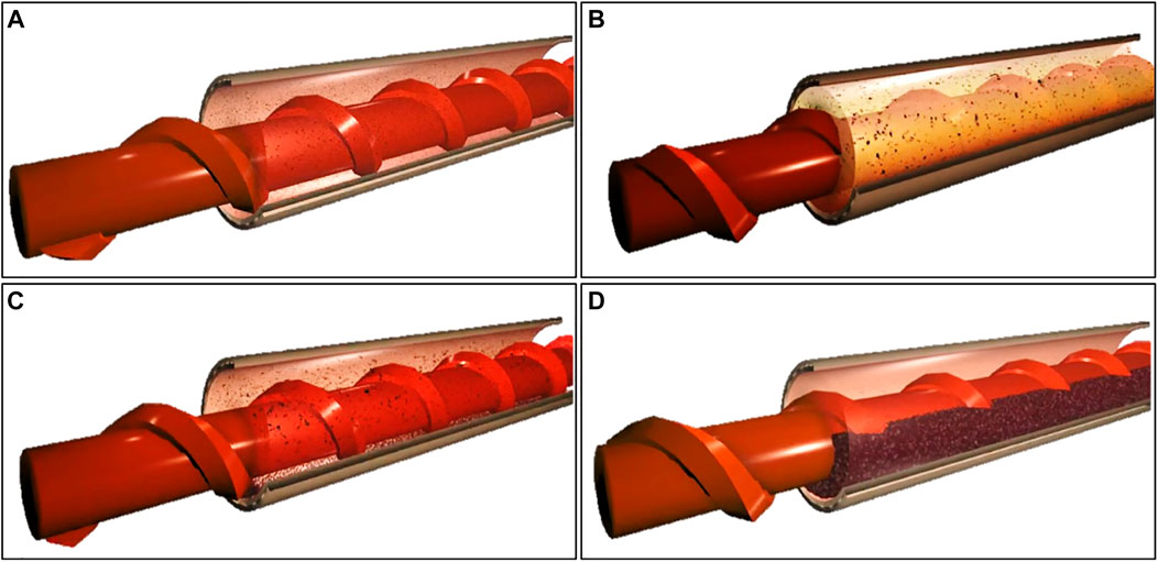
FIGURE 1. The annular solid-liquid flow model. (A) Homogeneous suspended state; (B) Inhomogeneous suspended state; (C) Moving laminar flow regime; (D) Fixed laminar flow regime.
The homogeneous suspended state means that coal particles are completely uniformly diffused in liquids (Figure 1A). The flow model cannot be formed unless coal particles show a small size and small mass and are transported at a high speed in the completely turbulent state. In most cases, coal particles are in an inhomogeneous suspended state. On this condition, the concentration of coal particles in liquids presents a gradient along the cross section of the liquids, in which the Figure 1B concentration at the bottom is higher than that on the top (Figure 1B). With the reduction of the flow velocity and the growth of the particle density, the particles with a large size start to deposit at the bottom of liquids, thus forming a deposition layer. Within a certain transporting range, the deposition layer slides in liquids along the flow direction while coal particles above the layer flow at an inhomogeneous suspended state, which is called moving laminar flow regime (Figure 1C). As the flow velocity further drops, more coal particles deposit at the bottom of the boreholes and finally a fixed deposition layer is formed at the bottom, which is called the fixed laminar flow regime (Figure 1D).
Mechanical Analysis of Coal Particles in Various Motion Stages
According to the motion states of coal particles in coal-liquid two-phase flow from low to high flow velocities, coal particles experience four motion stages, including initiation, rolling, sliding and suspending stages.
Initiation Stage
The particles in the surface layer of coal particle groups generally roll in the initiation stage. Therefore, it is possible to explore the problem of coal particles in the initiation stage by performing the mechanical analysis on a single coal particle.
The force driving the sliding of the coal particle is calculated as follows:
The resistance to the coal particle is expressed as follows:
where,
It can be obtained that coal particles are subjected to the effects of two force moments at the moment of rolling, which are separately expressed as follows:
The force moment driving the rolling of coal particles is calculated as follows:
The force moment resisting the rolling of coal particles is expressed as follows:
To make coal particles roll, it is necessary to satisfy
Rolling Stage
After coal particles roll, the drag force of water flow on coal particles constantly rises with the growing velocity of the water flow field, thus prompting more coal particles to roll. As a result, the motion of a single or multiple coal particles progressively transforms to rolling motion of coal particle groups.
Sliding Stage
As the velocity of the water flow field continues to grow, the force moment of rolling particles reverses, that is,
Suspending Stage
After the velocity of the water flow field further increases on the basis of the sliding stage, the turbulence of the water flow field is further strengthened and the fluctuating lift of water flows constantly increases. Eventually, the fluctuating lift is larger than the effective gravity of coal particles and therefore coal particles are in the suspending state. In this context, the force condition of coal particles is calculated as follows:
where,
According to the research results obtained by scholars in China, the average fluctuating lift of water flows is expressed as follows:
where,
It can be found that the solid-liquid two-phase flow in boreholes should be in a moving laminar flow regime in order to successfully discharge coal-cinder particles from the borehole orifice during the hydraulic cutting. In the case, the coal-cinder particles at the bottom of boreholes slide. If the concentration of coal particles or the flow velocity further declines, the motion state of coal particles in boreholes varies from the sliding state to rolling state. Furthermore, large-size coal particles start to deposit at the bottom of boreholes, thus further causing the borehole jamming. Therefore, the minimum flow velocity in boreholes should be the critical flow velocity at the moving laminar flow regime to ensure the successful drainage of coal cinders.
Relationship Between Cutting Pressure and Coal Breaking During Hydraulic Cutting
Relationship Between Cutting Pressure and Flow Rate
The dynamic pressure of water jets at the nozzle outlet is calculated as follows:
where, where P0, ρ0 and v0 separately represent the dynamic pressure at the nozzle outlet, the water density and the axial velocity at the nozzle outlet.
When water jets are just ejected out of the nozzle outlet, it is thought that the velocities at different positions of jets keep unchanged (being the axial velocity). Thus, the relationship between the jet flow rate and the velocity is expressed as follows:
By synchronously calculating Eqs. 11, 12, it can be attained that:
where, k0 and d denote the nozzle coefficient (0.95) and the nozzle diameter (2.5 × 10⁻³ m), respectively.
Relationship Between Cutting Pressure and Coal-Dropping Speed
To analyze the relationship between different cutting pressure and coal-dropping speed during the cutting in coal seams with different Protodyakonov coefficients, the field test was carried out by selecting four mines with different Protodyakonov coefficients of coal seams. The basic conditions of the mines are displayed in Table 1.
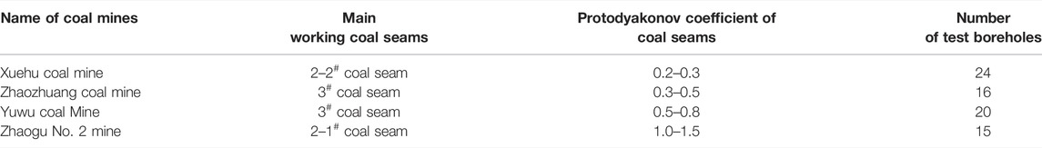
TABLE 1. Basic conditions of the test mines.
The ultra-high pressure hydraulic cutting test was conducted in the following four mines and the test results were described as follows:
The Ultra-High Pressure Hydraulic Cutting Test on Xuehu Coal Mine
Xuehu Coal Mine, located in the north of Yongcheng, Henan Province, China, is subordinated to Xuehu village in Yongcheng city. The 2-2# coal seam in Xuehu Coal Mine is taken as the main working coal seam. The coal seams in the coalfield occur steadily, with the thickness of 0–4.77 m, average thickness of 2.23 m, gas content within 4.6–16.2 m3/t and gas permeability coefficient of 0.0861 m3/(MPa2·d). The Protodyakonov coefficient of the 2-2# coal seam is in the range of 0.25–0.7 and the attenuation coefficient of gas flows within the boreholes with one hundred meters is 1.38 days−1. As for the test design, four groups of boreholes, each containing six boreholes, were distributed in the end-located drainage roadway of the No. 2306 airway in the mine, with 24 boreholes for hydraulic cutting in total. The hydraulic cutting was conducted in the four groups of boreholes for hydraulic cutting by separately using the cutting pressures of 40, 50, 60 and 70 MPa, during which coal outputs within the cutting time from borehole orifices were recorded. The test results are shown in Figure 2.
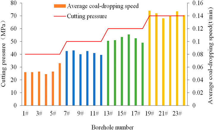
FIGURE 2. Relationship curve between the cutting pressure and the coal-dropping speed in coal seams with Protodyakonov coefficient in the range of 0.2–0.3.
As shown in Figure 2, when the cutting pressures are 40, 50, 60 and 70 MPa, the average coal-dropping speeds of the coal seams with Protodyakonov coefficient of 0.2–0.3 are 0.052, 0.081, 0.10 and 0.143 t/min, respectively.
The Ultra-High Pressure Hydraulic Cutting Test in Zhaozhuang Coal Mine
Zhaozhuang Coal Mine field is located in the southeast of Qinshui Coalfield, 53 km to the north of Jincheng City (Shanxi Province), 12 km to the north of Gaoping City, and 16 km to the south of Zhangzi County (Shanxi Province). The northern part of the coalfield is a sedimentary basin at Changzhi fault, and the middle and the southern parts correspond to the middle mountain areas eroded by Qinhe and Danhe river basins. In terms of the terrain of the areas, the altitude gradually reduces from the eastern and western parts to the middle part. To be specific, the highest point is situated in the northwest of Jubang Village at the western border, with the altitude of +1276.40 m; and the lowest point lies in the Dongdan River Valley in Guanzhai Village in the south, with the altitude of +880.70 m. It can be attained that the maximum relative altitude difference is 395.70 m. The bedrock in the southern and northern parts is mostly covered while that in middle and western parts are favorably outcropped. The coal-bearing strata in the coalfield are mainly subordinated to the Taiyuan Formation (C3t) of the upper series of Carboniferous system and the Shanxi Formation (P1s) of the lower series of Permian system, with shed coal scattered in the Lower Shihezi Formation and Benxi Formation. From top to bottom, Shanxi Formation contains 1#, 2# and 3# coal seams and Taiyuan Formation contains 12 coal seams including 5#, 6#, 7#, 8−1#, 8−2#, 9#, 11#, 12#, 13#, 14#, 15# and 16#. The cumulative total thickness of Shanxi Formation and Taiyuan Formation is in the range of 118.19–206.86 m, generally showing the thickness of 153.57 m. The two formations involve 15 coal seams, with the total thickness of 3.38–18.21 m, the average thickness of 12.80 m and the coal-bearing coefficient of 8.33%.
The average thickness of the 3# coal seam in Zhaozhuang Coal Mine in the whole area is 4.69 m, with Protodyakonov coefficient in the range of 0.3–0.5. Four groups of boreholes were constructed in the airway in the north of Zhaozhuang Coal Mine, each of which contained four boreholes, showing 16 boreholes in total. The cutting test was carried out on four groups of boreholes by separately applying the cutting pressure of 50, 60, 70 and 80 MPa. The test results are shown in Figure 3. Under the cutting pressures of 50, 60, 70 and 80 MPa, the average coal-dropping speeds of the coal seams with Protodyakonov coefficient within 0.3–0.5 were 0.040, 0.056, 0.092 and 0.119 t/min, respectively.
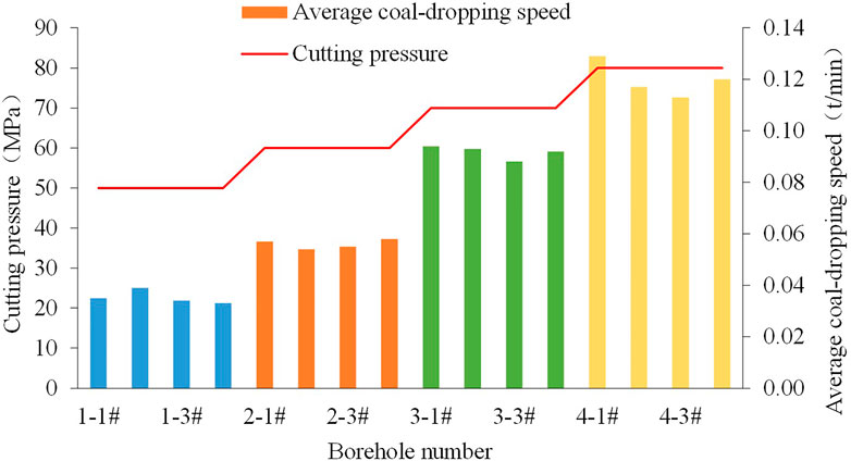
FIGURE 3. Relationship curve between the cutting pressure and the coal-dropping speed in coal seams with Protodyakonov coefficient in the range of 0.3–0.5.
The Ultra-High Pressure Hydraulic Cutting Test in Yuwu Coal Mine
The 3# coal seam in Yuwu Coal Mine of Lu’an Chemical Group Co., Ltd. is located in the middle and lower part of Shanxi Formation of the lower series of Permian system. The coal seam with a large thickness is stable and recoverable in the whole area, which is 24.00–42.00 m (with an average of 33.00 m) away from K8 sandstone above and 50.48–73.12 m (with an average of 62.00 m) away from the 9# coal seam below. The coal seam shows the thickness in the range of 5–7.25 m, with the average thickness of 5.99 m and Protodyakonov coefficient of 0.5–0.8. The ultra-high pressure hydraulic cutting test was performed in the N1103 belt conveyor roadway (with the designed total length of about 2,068 m), with coal on the north, the N1103 working face (unmined) on the west, N1105 belt conveyor roadway (being excavated) on the east and connected to the 1# ventilation roadway (excavated) in the west wing of the northern air shaft on the south. The N1103 belt conveyor roadway was excavated along the roof of the 3# coal seam with the thickness of 6 m. In the excavation direction of the roadway, the dip angle of the 3# coal seam was in the range of +3° ∼ −2°, showing the average dip angle of 1°. The N1103 belt conveyor roadway appeared as a rectangular cross section with the width of 5.4 m and height of 3.8 m, which was supported by using anchor nets and then strengthened with anchor cables. The N1103 belt conveyor roadway was pre-drained by drilling long boreholes with the length of 135 m, dip angle of 1°, azimuth of 270° and spacing of 4.0 m along coal seams. In the N1103 belt conveyor roadway in Yuwu Coal Mine, four groups of boreholes were distributed along the seams, each of which five boreholes were drilled, with 20 test boreholes in total. The cutting test was conducted on the boreholes under the cutting pressures of 60, 70, 80 and 90 MPa, respectively. The test results are shown in Figure 4.
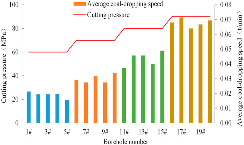
FIGURE 4. Relationship curve between the cutting pressure and coal-dropping speed in coal seams with Protodyakonov coefficient in the range of 0.5–0.8.
It can be seen from Figure 4 that under the cutting pressures of 60, 70, 80 and 90 MPa, the average coal-dropping speeds in coal seams with Protodyakonov coefficient of 0.5–0.8 were 0.019, 0.030, 0.044 and 0.068 t/min, respectively.
The Ultra-High Pressure Hydraulic Cutting Test in Zhaogu No. 2 mine
The main working coal seam 2-1# in Zhaogu No. 2 mine delivered the thickness of 4.73–6.77 m, with the average thickness of 6.16 m and Protodyakonov coefficient in the range of 1.0–1.5. Three groups of boreholes were designed in the belt roadway in the west of the mine, in which five boreholes were distributed in each group, amounting to 15 test boreholes. The cutting test was performed in the boreholes under the cutting pressures of 80, 90 and 100 MPa. Figure 5 shows the test results.
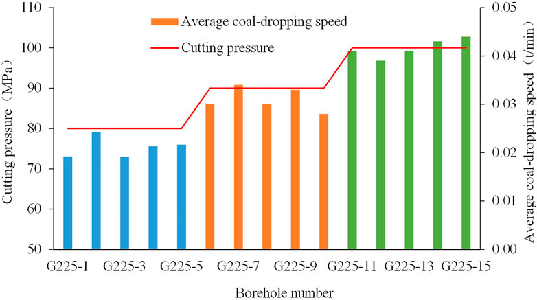
FIGURE 5. Relationship curve between the cutting pressure and the coal-dropping speed in the coal seam with Protodyakonov coefficient within 1.0–1.5.
As shown in Figure 5, the average coal-dropping speeds in the coal seam with Protodyakonov coefficient within 1.0–1.5 were 0.021, 0.031 and 0.042 t/min under the cutting pressures of 80, 90 and 100 MPa, respectively.
Through the above field tests, the changes of the coal-dropping speed in the coal seams with different Protodyakonov coefficients under different cutting pressures can be summarized, as shown in Table 2.
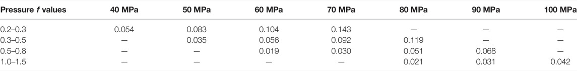
TABLE 2. The coal-dropping speeds in coal seams with different Protodyakonov coefficients under different cutting pressures.
By fitting the above data according to the negative exponent curve, the change curves between the jet pressure and the coal-dropping speed in coal seams with different Protodyakonov coefficients can be attained, as shown in Figure 6.
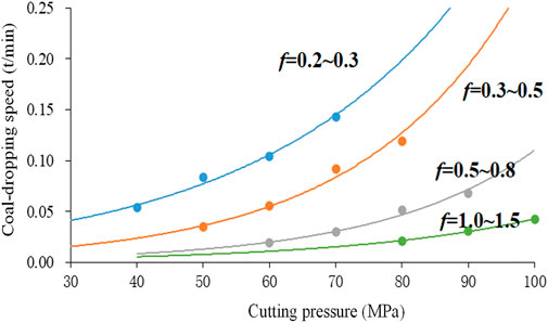
FIGURE 6. The change curve between the jet pressure and the coal-dropping speed.
As shown in Figure 6, the larger the cutting pressure is, the larger the coal-dropping speed during hydraulic cutting; moreover, with the growth of the cutting pressure, the coal-dropping speed during hydraulic cutting exponentially rises. Therefore, during high pressure cutting, the coal output dramatically increases due to the growth of the cutting pressure, thus leading to the borehole jamming and borehole outburst. The determination of a reasonable cutting pressure decisively influences the hydraulic cutting technology.
Pressure Selection for Coordinated slag Disposal During Hydraulic Cutting
Critical Flow Velocity at the Moving Laminar Flow Regime
According to the mechanical analysis on coal particles in Relationship Between Cutting Pressure and Coal-Dropping Speed, it can be seen that coal particles are mainly subjected to the uplift force of fluids, effective gravity of particles and the drag force of fluids. The drag force of fluids drives coal particles to move forward while the effective gravity and the uplift force of fluids are forces with contrary directions in the vertical direction.
Therefore, the critical flow velocity
where, Fg, Fd and
Thus,
where,
The drag force coefficient of coal particles can be determined according to the following equation:
where, vt denotes the deposition velocity (m/s) of coal particles;
Therefore, Eq. 12 can be transformed as follows:
Owing to
Thus, the critical flow velocity at the moving laminar flow regime can be obtained by using the dimensional analysis.
where, a stands for the comprehensive factor for characterizing the shape factors of coal particles.
Critical Relationship Between the Flow Rate and the slag-Disposal Capacity
To calculate the numerical relationship between the flow rate and the slag-disposal capacity, the dimensionless analysis is employed to solve Eq. 16. The annular solid-liquid two-phase flow model for coal particles and water is solved according to Eq. 16 based on various parameters. To be specific, R and r are 0.113 m and 0.073 m and thus D = 0.086 m; ds and S equal 0.001 m and 1.42. By substituting them into Eq. 16, it can be attained that:
By substituting
where, vp and vf separately denote the volumes of coal particles and liquid, respectively.
By substituting
By substituting Eq. 3 into Equation (23), it can be obtained that:
Through the above calculation, the relationship between the cutting pressure and the critical slag disposal amount is obtained.
Model for the Coordinated slag Disposal During Hydraulic Cutting
By substituting Eq. 20 into Figure 7, the model for the coordinated slag disposal during the cutting can be attained, as shown in Figure 7.
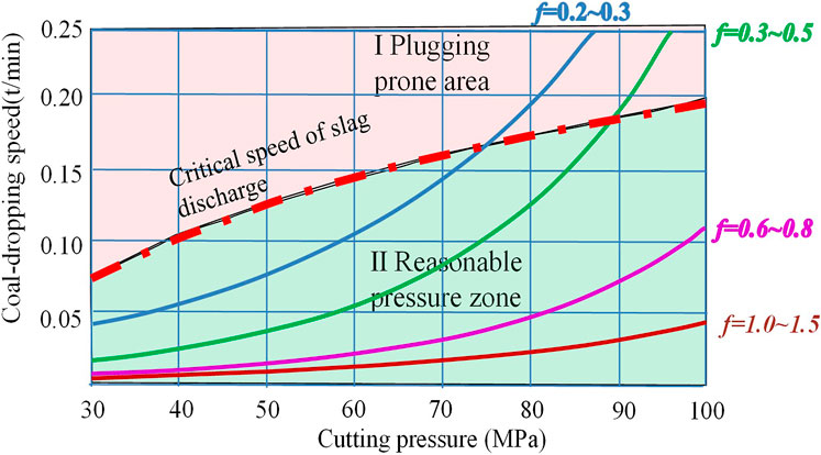
FIGURE 7. Model for the coordinated slag disposal during the cutting.
Through analysis according to the results of theoretical calculation and the field data, it is found that by taking the critical curve for the slag disposal as the boundary, zone I is the position where the borehole jamming is likely to occur. When the selected pressure corresponds to the zone I, the coal output from boreholes is quite large and exceeds the critical slag disposal amount, thus easily leading to the borehole jamming; in the case that the pressure corresponds to the zone II, the coal output is lower than the critical slag disposal amount. On this condition, it is possible to achieve the expected cutting effect and also successfully discharge coal cinders from boreholes. Therefore, when selecting the cutting parameters, it is necessary to select the cutting pressure within the zone II, thus realizing the optimal cutting effect. It can be seen from the figure that the critical pressure inducing the borehole jamming is in the range of 70–75 MPa when Protodyakonov coefficient of coal seams ranges from 0.2 to 0.3 and it is within 80–85 MPa in the case that Protodyakonov coefficient of coal seams is in the range of 0.3–0.5.
Field Test
Selection of Test Schemes
The No. 2 mine in China Coal Xinji Energy Co., Ltd. (Xijin coal mine No. 2) was used as the test mine and the 220112 working face was taken as the test area, as shown in Figure 8. The 1# coal seam group in 2201 mining area was divided into the 1# upper coal seam and 1# coal seam, with the average thicknesses of 3.4 and 3.9 m, respectively. The 1# upper coal seam and 1# coal seam showed an average spacing of 0.9 m and a dip angle of 5°. Through measurement, the maximum gas pressure, the gas content and Protodyakonov coefficient of 1# coal seam were 1.65 MPa, 6.8–8.2 m3/t and 0.48, respectively. As for the borehole design, 25 horizontal test boreholes (G1 ∼ G25) were distributed in the machinery roadway of the working face and 20 boreholes (D1 ∼ D20) were used for comparison, showing the spacing of 10 m and borehole depth of 120 m; the spacing between the boreholes for hydraulic cutting and those for comparison was set as 20 m. The boreholes G1 ∼ G5 were test boreholes for exploring the reasonable cutting pressure. The cutting test was separately carried out under different cutting pressures, during which the cutting time, slag disposal amount and the water- and slag-return conditions were recorded. After determining the reasonable cutting pressure, the ultra-high pressure hydraulic cutting test was conducted to explore the coal output and net gas extraction; afterwards, the comparative analysis was made with those from boreholes for comparison.
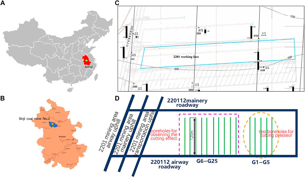
FIGURE 8. Test positions; (A) the position in Anhui Province; (B) the position of the Xijin coal mine No. 2; (C) test positions; (D) distribution of test boreholes.
Result Analysis of Test Boreholes for the Reasonable Cutting Pressure
The cutting parameters and conditions obtained from the test boreholes G1 ∼ G5 for the reasonable
As shown in Table 3, as for test boreholes G1 and G2, the coal output is low under the cutting pressure of 50–60 MPa while it significantly rises when the cutting pressure is in the range of 70–80 MPa; after the pressure grows to 90 MPa, the severe borehole jamming and borehole outburst appear in the borehole G5. It indicates that the reasonable cutting pressure should be about 80 MPa for coal seams with the Protodyakonov coefficient of about 0.48, which conforms to the result obtained according to the model for the coordinated slag disposal during hydraulic cutting.
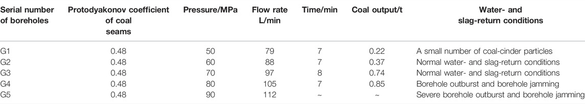
TABLE 3. Cutting condition based on the test boreholes for the reasonable cutting pressure.
Analysis of the Coal Output From the Boreholes for Hydraulic Cutting
Figure 9 displays the coal output from boreholes for hydraulic cutting. It can be seen from the figure that the average coal output per cutting of 20 boreholes for hydraulic cutting (G6 ∼ G25) reaches the minimum of 0.69 t and the maximum of 1.06 t, with the mean value of 0.87 t. The equivalent radius is calculated as 2.15 m. During hydraulic cutting of 20 boreholes, the poor slag disposal conditions (such as borehole jamming and borehole outburst) do not occur, which also validates the selection rationality of the cutting pressure.
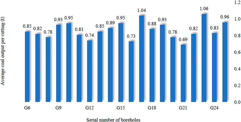
FIGURE 9. Coal output from boreholes for hydraulic cutting.
Comparative Analysis of the Gas Extraction Effect
Figure 10 shows the change curves of the average net gas extraction from a single borehole for hydraulic cutting and a conventional borehole within 60 days of extraction.
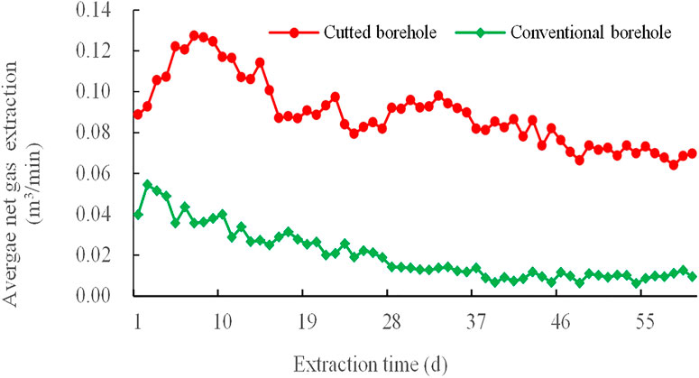
FIGURE 10. Changes curves of the average net gas extraction from a single borehole for hydraulic cutting and a conventional borehole.
It can be seen from the figure that the maximum and minimum of the average net gas extraction from boreholes for hydraulic cutting are 0.127 and 0.064 m3/min, with the mean value of 0.089 m3/min, while those from conventional boreholes are 0.054 and 0.006 m3/min, with the mean value of 0.020 m3/min, respectively. The average net gas extraction from boreholes for hydraulic cutting is 4.5 times larger than that from conventional boreholes.
Observation on the Permeability of Coal Seams
Before performing the ultra-high pressure hydraulic cutting, the original gas permeability coefficient of 1# coal seam of the machinery roadway in the 220,112 working face is calculated as 0.03962 m2/MPa2·d based on the method proposed by China University of Mining and Technology. After conducting the ultra-high pressure hydraulic cutting, the gas permeability coefficient of the 1# coal seam is measured as 0.9905 m2/MPa2·d, which increases by 25 times than the original one.
Comparison of the Effective Extraction Radius
The effective extraction radiuses around the boreholes for hydraulic cutting and conventional boreholes after extraction for 30 and 60 days are shown in Table 4. After the cutting, the impact area of the boreholes for hydraulic cutting greatly increases and the effective extraction radius is more than doubled relative to conventional boreholes.
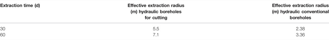
TABLE 4. Comparison of the effective extraction radiuses around boreholes for hydraulic cutting and conventional boreholes.
In summary, the field tests were conducted after determining a reasonable cutting pressure. The comparison of the coal output from the boreholes for hydraulic cutting, the gas extraction effect, the permeability of coal seams, and the comparison of the effective extraction radius for hydraulic cutting was analyzed. The field test results show that the reasonable cutting pressure can ensure the safety of cutting operation and improve the extraction effect.
Conclusion
In this paper, a model for coordinated slag disposal during hydraulic cutting based on coal-water two-phase flow was established according to the annular solid-liquid two-phase flow theory. Besides, the model for selecting the reasonable cutting pressure was used to guide the field test. The primary conclusions are displayed as follows.
(1) By analyzing the test data on four mines containing coal seams with different Protodyakonov coefficients obtained through the field cutting test, the relationship curves between the coal-dropping speed and the cutting pressure under different Protodyakonov coefficients were attained; moreover, it suggested that the coal-dropping speed during hydraulic cutting exponentially increases with the growth of the cutting pressure.
(2) By constructing the annular solid-liquid two-phase flow model with coal-water mixture, the mechanical condition of coal particles at different motion stages was analyzed. The result showed that the concentration and flow velocity of coal-water two-phase flow are main factors influencing the slag disposal from boreholes; the critical flow velocity at the moving laminar flow regime is considered as that for the coordinated slag disposal from boreholes.
(3) Through mechanical analysis of the moving laminar flow regime of coal-cinder particles, the critical flow velocity at the moving laminar flow regime was obtained. In addition, the model for selecting the reasonable cutting pressure based on the coordinated slag disposal theory was established according to the curve relationship with the coal-dropping speed, which guided the cutting test on the 220112 working face. When the reasonable cutting pressure during the slag disposal in the coal seam with Protodyakonov coefficient of 0.48 was determined as about 80 MPa, no borehole outburst and borehole jamming were found during the cutting of test boreholes, with the average coal output per cutting of 0.87 t and the equivalent radius of 2.15 m. The average net gas extraction from boreholes for hydraulic cutting was 4.5 times of that from conventional boreholes; additionally, relative to conventional boreholes, the gas permeability coefficient rose by 25 times and the effective extraction radius is more than doubled.
(4) The test results showed that the model for selecting the reasonable cutting pressure based on the coordinated slag disposal theory clarified the relationships of the cutting pressure, coal-dropping speed and the critical slag disposal amount. It can ensure the safety of the cutting operation while improving the extraction effect during hydraulic cutting, which effectively guides the selection of the cutting pressure in field tests.
Data Availability Statement
The raw data supporting the conclusions of this article will be made available by the authors, without undue reservation.
Author Contributions
The authors have made a significant contribution to the manuscript. YZ was responsible for the framework design and writing of the paper, FJ was responsible for the theoretical analysis in the manuscript and QZ was responsible for the revision of the manuscript.
Funding
This work is financially supported by the Tiandi Technology Co., Ltd. for the special funding of Science and Technology Innovation and Entrepreneurship Fund (2021-2-TD-ZD008), the Regional Innovation Development Joint Fund Key Project (U21A20110), the State Key Laboratory Open Fund Project (SKLMRDPC20KF01), and the National Natural Science Foundation of China (52074041), which are gratefully acknowledged.
Conflict of Interest
The authors declare that this study received funding from the Tiandi Technology Co., Ltd. The funder had the following involvement in the study: study design, collection, analysis, interpretation of data.
Publisher’s Note
All claims expressed in this article are solely those of the authors and do not necessarily represent those of their affiliated organizations, or those of the publisher, the editors and the reviewers. Any product that may be evaluated in this article, or claim that may be made by its manufacturer, is not guaranteed or endorsed by the publisher.
References
Cheng, Y., Fu, J., and Yu, Q. (2009). Development of Coal Mine Gas Drainage Technology in China. J. Mining Saf. Eng. 26 (2), 127–139.
Guo, D., Lv, P., Zhao, J., and Zhang, C. (2020). Research Progress on Permeability Improvement Mechanisms and Technologies of Coalbed Deep-Hole Cumulative Blasting. Int. J. Coal Sci. Technol. 7 (2), 329–336. doi:10.1007/s40789-020-00320-5
Guo, H., Wang, K., Wu, Y., Tang, H., Wu, J., Guan, L., et al. (2021). Evaluation of the Weakening Behavior of Gas on the Coal Strength and its Quantitative Influence on the Coal Deformation. Int. J. Mining Sci. Technol. 31 (03), 451–462. doi:10.1016/j.ijmst.2021.03.005
Han, S. M., Woo, N. S., Ha, J. H., Kim, T., Kim, Y. J., and Kim, S. M. (2020). Flow Characteristics of a Solid-Liquid Non-newtonian Fluid for Directional Drilling. J. Nanosci Nanotechnol 20 (1), 384–395. doi:10.1166/jnn.2020.17239
He, M., Zhang, Z., Zhu, J., and Li, N. (2021). Correlation between the Constant Mi of Hoek-Brown Criterion and Porosity of Intact Rock. Rock Mech. Rock Eng. 55, 923–936. doi:10.1007/s00603-021-02718-2
He, M., Zhang, Z., Zhu, J., Li, N., Li, G., and Chen, Y. (2021). Correlation between the Rockburst Proneness and Friction Characteristics of Rock Materials and a New Method for Rockburst Proneness Prediction: Field Demonstration. J. Pet. Sci. Eng. 205, 108997. doi:10.1016/j.petrol.2021.108997
Hu, Q., Jiang, S., and Su, W. (2000). Countermeasures for Prevention and Control of Coal Mine Gas Disaster in China. Mining Saf. Environ. Prot. 2000 (01), 58–61.
Ilker, P., and Sorgun, M. (2020). Performance of Turbulence Models for Single Phase and Liquid-Solid Slurry Flows in Pressurized Pipe Systems. Ocean Eng. 2020, 214. doi:10.1016/j.oceaneng.2020.107711
Jia, L., Li, K., Shi, X., Zhao, L., and Jianshe, L. (2021). Application of Gas Wettability Alteration to Improve Methane Drainage Performance: A Case Study. Int. J. Mining Sci. Technol. 31 (04), 621–629. doi:10.1016/j.ijmst.2021.04.002
Kramer, O. J. I., Padding, J. T., van Vugt, W. H., de Moel, P. J., Baars, E. T., Boek, E. S., et al. (2020). Improvement of Voidage Prediction in Liquid-Solid Fluidized Beds by Inclusion of the Froude Number in Effective Drag Relations. Int. J. Multiphase Flow 127. doi:10.1016/j.ijmultiphaseflow.2020.103261
Liang, Y., Ran, Q., Zou, Q., Zhang, B., and Hong, Y. (2022). Experimental Study of Mechanical Behaviors and Failure Characteristics of Coal under True Triaxial Cyclic Loading and Unloading and Stress Rotation. Nat. Resour. Res. doi:10.1007/s11053-022-10022-1
Lin, B., Fazhi, Y., Zhu, C. J., Zhou, Y., Quanle, Z., Chang, G., et al. (2015). Cross-borehole Hydraulic Slotting Technique for Preventing and Controlling Coal and Gas Outbursts during Coal Roadway Excavation. J. Nat. gas Sci. Eng. 26, 518–525.
Liu, J. H., and Zhu, M. Y. (2011). Numeration Simulation of Solid-Liquid Two-phase Flow in Centrifugal Sewerage Pump. Amm 44-47, 345–348. doi:10.4028/www.scientific.net/AMM.44-47.345
Shen, C., Lin, B., Sun, C., Zhang, Q., and Li, Q. (2015). Analysis of the Stress-Permeability Coupling Property in Water Jet Slotting Coal and its Impact on Methane Drainage. J. Pet. Sci. Eng. 126, 231–241. doi:10.1016/j.petrol.2014.11.035
Wang, K., and Zhang, X. (2006). Development Status and prospect of China's Coal Mine Gas Drainage Technology. China Coal Bed Methane 2006 (01), 13–16+39.
Wang, Q., He, M., Li, S., Jiang, Z., Wang, Y., Qian, Q., et al. (2021). Comparative Study of Model Tests on Automatically Formed Roadway and Gob-Side Entry Driving in Deep Coal Mines. Int. J. Mining Sci. Technol. 31 (04), 591–601. doi:10.1016/j.ijmst.2021.04.004
Wang, Y., Sun, Y., Chun, L., He, Z., and Wang, Z. (2016). Dynamic Characteristics and Application of Drilling Cuttings Migration in Soft Coal Seam Drilling Hole Area. J. Mining Saf. Eng. 33 (06), 1138–1144.
Wei, N., Xu, H., Sun, W., Zhao, J., Zhang, L., Fu, Q., et al. (2017). Migration Law of Solid Particles of Natural Gas Hydrate with Different Abundances in Horizontal Well Section. Nat. Gas Industry 37 (12), 75–80.
Yamaguchi, H., Niu, X., Shogo, N., and Florian, D. V. (2011). Solid-liquid Two-phase Flow_measurement Using An_electromagnetically Induced Signal Measurement Method. J. Fluids Engineering-Transactions Asme 133 (4), 041302. doi:10.1115/1.4003856
Yang, X. (1994). Study on Cuttings Migration and Critical Speed in Spiral Drilling. J. China Univ. Mining Technol. 1994 (04), 101–108.
Yang, X., Zhang, Y., and Ren, C. (2012). The Numerical Simulation for Seepage Rule of Coal-Bed Methane with Hydraulic Cutting Seam Mining Based on Matlab. Adv. Mater. Res. 2012, 1792. doi:10.4028/www.scientific.net/amr.524-527.485
Yi, M., Wang, L., Hao, C., Liu, Q., and Wang, Z. (2021). Method for Designing the Optimal Sealing Depth in Methane Drainage Boreholes to Realize Efficient Drainage. Int. J. Coal Sci. Technol. 8 (6), 1400–1410. doi:10.1007/s40789-021-00448-y
Zhang, B., Sun, H., Liang, Y., Wang, K., and Zou, Q. (2019). Characterization and Quantification of Mining-Induced Fractures in Overlying Strata: Implications for Coalbed Methane Drainage. Nat. Resour. Res. 29 (4). doi:10.1007/s11053-019-09600-7
Zhang, T., Zou, Q., Jia, X., Liu, T., Jiang, Z., Tian, S., et al. (2022). Effect of Cyclic Water Injection on the Wettability of Coal with Different SiO2 Nanofluid Treatment Time. Fuel 312. doi:10.1016/j.fuel.2021.122922
Zhang, X., Li, J., Zhou, Z., and Zhao, W. (2017). Numerical Analysis and Experimental Study on Micro-holes in Solid-Liquid Two-phase Abrasive Flow Machining. J. Measurements Eng. 5 (3), 176–181. doi:10.21595/jme.2017.19103
Zhao, Y., Lin, B., Liu, T., Kong, J., and Zheng, Y. (2020). Gas Flow in Hydraulic Slotting-Disturbed Coal Seam Considering Stress Relief Induced Damage. J. Nat. Gas Sci. Eng. 75. doi:10.1016/j.jngse.2020.103160
Zhou, A., Zhang, M., Wang, K., and Elsworth, D. (2021). Near-source Characteristics of Two-phase Gas-Solid Outbursts in Roadways. Int. J. Coal Sci. Technol. 8 (4), 685–696. doi:10.1007/s40789-020-00362-9
Zou, Q., Han, L., Jiang, Z., and Wu, X. (2021). Gas Flow Laws in Coal Subjected to Hydraulic Slotting and a Prediction Model for its Permeability-Enhancing Effect. Energy Sourc. A: Recovery, Utilization, Environ. Effects 2021. doi:10.1080/15567036.2021.1936692
Zou, Q., Liu, H., Zhang, Y., Li, Q., Fu, J., and Hu, Q. (2020). Rationality Evaluation of Production Deployment of Outburst-Prone Coal Mines: A Case Study of Nantong Coal Mine in Chongqing, China. Saf. Sci. 122, 104515. doi:10.1016/j.ssci.2019.104515
Keywords: hydraulic cutting, cutting pressure, coordinated slag disposal, solid-liquid, two-phase flow
Citation: Zhang Y, Ji F and Zou Q (2022) Coordinated slag Disposal From Horizontal Boreholes During Hydraulic Cutting Based on Two-Phase Flow Theory. Front. Earth Sci. 10:817531. doi: 10.3389/feart.2022.817531
Received: 18 November 2021; Accepted: 21 March 2022;
Published: 14 April 2022.
Edited by:
Qingsheng Bai, Freiberg University of Mining and Technology, GermanyReviewed by:
Mingming He, Xi’an University of Technology, ChinaHuafu Qiu, Xi’an University of Science and Technology, China
Huabin Zhang, Liaoning Technical University, China
Copyright © 2022 Zhang, Ji and Zou. This is an open-access article distributed under the terms of the Creative Commons Attribution License (CC BY). The use, distribution or reproduction in other forums is permitted, provided the original author(s) and the copyright owner(s) are credited and that the original publication in this journal is cited, in accordance with accepted academic practice. No use, distribution or reproduction is permitted which does not comply with these terms.
*Correspondence: Fei Ji, 872423807@qq.com; Quanle Zou, quanlezou2011@126.com