Unification of the Mechanical Model and Parameter Analysis of the Elastic Foundation Beam of Pipe-Roof
 Xiaojing Xu
 Zhanping Song
 Hui Li
 Xiaoxu Tian
 Guannan Zhou
- 1School of Civil Engineering, Xi’an University of Architecture and Technology, Xi’an, China
- 2Shaanxi Key Laboratory of Geotechnical and Underground Space Engineering, Xi’an, China
- 3China Railway Major Bridge Engineering Group, Tianjin, China
Based on the existing model of pipe-roof considering the arching effect, combined with the mechanical model of pipe-roof when the tunnel is excavated to the end, a unified mechanical model of the elastic foundation beam for pipe-roof is established. Deflection and internal force calculation formulas of the model were derived. Combined with actual engineering cases, the model was compared and analyzed, and the parameters affecting the pipe-roof were analyzed by taking the unified model as an example. The results show that the established unified elastic foundation beam model can better represent the actual stress state of a pipe-roof and the model has strong applicability. The stress state of the pipe-roof at the end of excavation can be calculated by changing the boundary conditions of the model. When the diameter of the steel pipe is 108–114 mm, the supporting effect of the pipe-roof is similar. When Ec (elastic modulus of converging) > 40.0Eg (elastic modulus of ground rock), the excavation footage and the diameter of the steel pipe have little effect on the deflection and bending moment of the pipe-roof. Therefore, increasing the elastic modulus of the reinforced area is the most effective method to reduce the deflection and internal force of the pipe-roof. The longer the residual length of the pipe-roof in surrounding rock, the safer the tunnel will be during excavation. The economically reasonable value of the residual length of the pipe-roof in surrounding rock is 2–3 m.
Introduction
With the development and utilization of underground space, many scholars are studying the failure mechanism of tunnel (Xiang et al., 2018; Chen et al., 2019). As a common auxiliary construction method that can effectively control the deformation of a tunnel in soft surrounding rock (Singh et al., 1995; Ocak, 2008; Aksoy and Onargan, 2010), pipe-roof pre-support technology has been widely used in the process of tunnel construction due to its advantages such as long-distance support, fast construction speed, and high safety (Miwa and Ogasawara, 2005; Han et al., 2021). The pipe-roof support is used to drill holes outside the outline of the tunnel to be excavated, insert steel pipes, and then, for grouting so that the slurry and surrounding rock form a bearing arch similar to the shell that bears the load from the upper part of the pipe-roof and restrain the deformation of the surrounding rock (Wang et al., 2018). Therefore, choosing a proper mechanical model of pipe-roof and designing reasonable pipe-roof parameters have an important influence on the control of tunnel deformation and construction safety.
The mechanical model of pipe-roof has been studied extensively by scholars at home and abroad. At present, there are mainly beam theory, arch shell theory, and elastic foundation beam theory in the analytical analysis of pipe-roof. In terms of beam theory, Xing and Xu (1999) simplified the opening section into a cantilever beam and the inner section into a simply supported beam to analyze the stress situation of the pipe-roof. However, the beam theory does not take into account factors such as the interaction between the pipe-roof and the surrounding rock and the supporting condition of the pipe-roof in the surrounding rock. Moreover, it simplifies the stress condition of the pipe-roof greatly, but its calculated value is generally different from the actual engineering. In the aspect of the theory of the arch shell, there are few pieces of research, mainly because the calculation of the force of the pipe-roof using the theory of the shell is complicated and the result is partially unsafe. In terms of elastic foundation beam, it is mainly divided into the Winkler elastic foundation beam model and Pasternak elastic foundation beam model with two parameters. Chang (1999) believed that the elastic foundation beam model could better simulate the mechanism of the pipe-roof and established the Winkler elastic foundation beam model for research. Based on the beam model of Winkler elastic foundation, Song et al. (2020a) established the stress analysis model of pipe-roof considering the integrity of the grouting convergence area and the delay of initial support, deduced the calculation formulas of pipe-roof deflection and internal force, and analyzed the excavation footage of pipe-roof and the diameter of steel pipe. Song et al. (2013) proposed the sorghum-spring structure model, developed the finite element software for calculating the bending moment and shear force of the steel pipe, and optimized the design parameters of the pipe-roof. Xiao et al. (2006) simplified the pipe-roof structure into a fixed beam and elastic foundation beam and then analyzed the mechanical effect of the pipe-roof structure in box culvert jacking in accordance with the bearing mechanism of the beam. Jia et al. (2010) considered the delay effect of initial support and established the Pasternak elastic foundation beam model and compared it with monitoring data. The results showed that the Pasternak model was closer to the actual stress situation. Li et al. (2011) monitored the deformation of the pipe-roof under a shallow-buried loess tunnel through the expressway and made an analytical calculation with the Pasternak elastic foundation model to analyze the deformation law of pipe-roof under stress. Wang et al. (2017) established the Pasternak elastic foundation model considering factors such as the delay of initial support, the time difference of stress release in the surrounding rock, and the uneven coefficient of formation and slope and solved the analytical solution of pipe-roof deformation by using the finite element idea and longitudinal shear stress transfer theory. Wu et al. (2019) established the model of anisotropic plate on an elastic foundation of pipe-roof based on the traditional beam model of elastic foundation of pipe-roof and compared the supporting effect of pipe-roof diameters of 76 and 108 mm, respectively, indicating that the diameter of the pipe-roof affects its effect of controlling the deformation of surrounding rock. Song et al. (2020b) used the elastic foundation beam, simply supported beam, and fixed supported beam model to calculate the force and deformation of pipe-roof and compared them with the monitoring data. The results showed that the elastic foundation beam and simply supported beam model could better reflect the mechanical behavior of pipe-roof. At present, the Winkler elastic foundation beam model and Pasternak double-parameter foundation beam model are mostly used for analytical analysis. The Winkler elastic foundation beam model has the characteristics of fewer parameters, is easy to determine, and has small effect of value error on the internal force. With the continuous development of analytical analysis, considering the delay of initial support, the change of the coefficient of subgrade reaction force and the load distribution of surrounding rock, integrity of grouting convergence area, and other factors, the results of the analytical analysis are closer to the actual monitoring values.
At present, there are many kinds of mechanical models for studying pipe-roof. In order to better study the actual forces of pipe-roof and make the models more practical and suitable for different situations, this article unifies the existing models. The unified elastic foundation beam model of the pipe-roof is obtained, the force and deformation of the pipe-roof are calculated based on specific engineering examples, and the calculation results of the model are analyzed. Finally, the influence parameters of the pipe-roof are analyzed.
The Establishment of a Unified Mechanical Model of Pipe-Roof
Stress Analysis of Pipe-Roof Grouting Convergence Area
Steel pipes, arranged in a certain range outside the tunnel contour, form a convergence area similar to the shell with certain integrity through grouting and surrounding rock, as shown in Figure 1 (Song et al., 2020a). The pipe-roof shell and the surrounding rock bear the load of the excavation face together to restrain the deformation of the surrounding rock, prevent the collapse of the tunnel roof, and achieve the purpose of safe construction of tunnels.
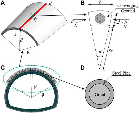
FIGURE 1. Force analysis of the grouting area in the pipe-roof.
When the load is distributed symmetrically along the lateral direction of the shell, the longitudinal direction can be any load distribution. A longitudinal strip AB is cut along the length direction of the pipe-roof shell so that the radial displacement of each point on the cross section of the pipe-roof shell can be regarded as the deflection of the longitudinal strip AB. If the deflection at any cross section C is
where R is the radius.
The circumferential strain is
Corresponding to the compression strain, the circumferential stress on the cross section of the pipe-roof shell is
Then, the normal force N on both sides of section C on unit length is
If the normal forces on both sides are combined, the direction of the resultant force p must be along the radius direction, and its size is
Substituting Eq. 4 into Eq. 5, while taking into account
where R is the radius of the pipe-roof convergence ring; t is the thickness of the convergence area; Ec is the elastic modulus of the convergence area; and b is the selected width of the unit body.
It can be seen from Eq. 6 that in addition to bearing the surrounding rock pressure that varies in the longitudinal direction, the longitudinal strip AB also receives p radial force that varies in the longitudinal direction. The direction of p is opposite to the direction of deflection
Construction of a Unified Mechanical Model of Pipe-Roof
In the process of pipe-roof mechanics analysis, the steel pipes in the pipe-roof are often regarded as beams, and the surrounding rock above the excavation area is regarded as the downward load acting on the steel pipes, that is, the “load-beam model.”
At present, many scholars (Wu and Song, 2007; Wang et al., 2019) consider the pipe-roof as the Winkle elastic foundation beam to analyze the stress state of the pipe-roof. The Winkler elastic foundation beam model regards the foundation as composed of many independent springs, as shown in Figure 2. It ignores the characteristics of continuous deformation, and considered that the displacement of a point on the foundation has nothing to do with the stress of other points, only related to the foundation reaction coefficient k. The Winkler elastic foundation beam model is easy to calculate and is suitable for shallow-buried soft ground. Therefore, it is widely used to analyze the action mechanism of pipe-roof in shallowburied weak tunnels.
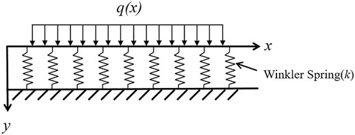
FIGURE 2. Winkler elastic foundation beam model.
According to the stress condition of the pipe-roof, as shown in Figure 3, the pipe-roof can be divided into A1O, the initial support section; OA2, the excavation section; A2B, disturbed section BC; and undisturbed section CD.
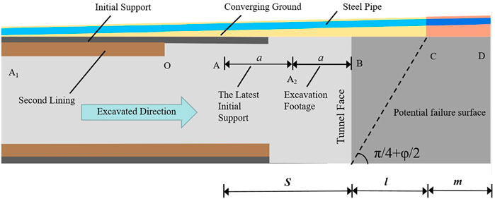
FIGURE 3. Schematic diagram of tunnel excavation and pipe-roof layout.
Figure 3 is simplified and combined with existing pipe-roof models, thus establishing a unified mechanical model of pipe-roof , as shown in Figure 4.
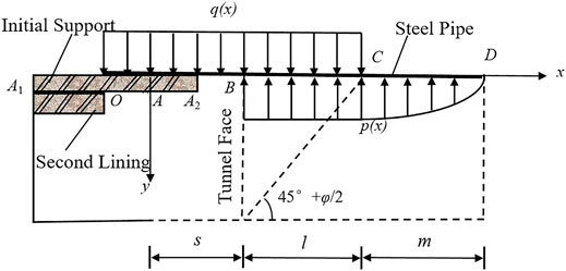
FIGURE 4. Analysis model of the mechanical behavior of the pipe-roof.
The unified model considers the secondary lining and the early initial support, the deformation delay of the latest initial support, the arching effect of the pipe-roof grouting to form the integral pipe-roof arch, the excavation disturbance section, and the excavation undisturbed section.
When solving the unified mechanical model of tunnel pipe-roof, the following assumptions are made:
1) The steel pipe in the pipe-roof is simplified as a Winkler elastic foundation beam. It is considered that the secondary lining and early initial support have played a role and can effectively control the deformation of the surrounding rock. Point A is set as the fixed end.
2) The arch effect of the pipe-roof arch formed by pipe-roof grouting is considered.
3) Considering the delay of initial support deformation, it is regarded that the newly applied initial support does not provide the required support. The length of the pipe-roof without support is assumed to be 2 times the excavation footage; that is, s = 2a and ‘a’ is the excavation footage.
4) The equivalent elastic modulus of AB and BC beams is jointly determined by using a steel pipe and grouting mortar.
where E1, I1 is the elastic modulus and section moment of inertia of the grouting mortar; E2, I2 is the elastic modulus and section moment of inertia of the steel pipe.
5) The length of section BC in the disturbance area in front of the tunnel face is determined by the potential failure surface in front of the tunnel face; then, the distance of BC in the disturbance area is
6) The load on the upper part of the pipe-roof is determined according to the Terzaghi formula, and the acting length of the load is s + l.
where γ is the weight of the surrounding rock; B is the width of the excavated tunnel; c is the cohesion of the surrounding rock; λ is the lateral pressure coefficient of the surrounding rock; φ is the internal friction angle of the surrounding rock; h is the thickness of the rock covering the upper part of the pipe-roof; p is the ground load; and δ is the steel pipe spacing.
7) Considering the undisturbed section m, the deflection and bending moment of the pipe-roof will continue to be transmitted outside the disturbed area in front of the tunnel face.
According to the theoretical force model of the beam on an elastic foundation, the deflection differential equation is
The deflection differential governing equations of different sections are as follows.
The governing equation of section AB:
The governing equation of section BC:
The governing equation of section CD:
In the formulas, E is the elastic modulus of the pipe-roof, I is the moment of inertia of the pipe-roof, b is the width of the elastic foundation beam, k1 = EcD/R2, k2 = k3 = EcD/R2+k0, k0 is the foundation reaction coefficient before excavation, Ec is the elastic modulus of the convergence area, and R is the diameter of the arch.
The differential governing equation of each section is solved as follows.
Section AB:
Section BC:
Section CD (t=x−s−l):
The boundary conditions are as follows: when x = 0,
We substitute the boundary conditions into Eqs. 15–17 to obtain Eq. 18 of the system of equations, namely,
The following equation is obtained:
Equation 19 is written in matrix form, i. e,
The elements of matrix [A] are as follows:
where F is defined as
The parameters MA、QA、
The Existing Mechanical Model of Pipe-Roof
Previous scholars have also conducted a lot of research on the mechanical model of the pipe-roof, in which they mainly considered the delay of the initial support, the change of the foundation reaction coefficient, and the uneven distribution of the surrounding rock load. The arch effect of the pipe-roof is less studied. Song et al. (2020a) considered the arching effect of the pipe-roof and established the pipe-roof model as shown in Figure 5. They simplified the pipe-roof into an elastic foundation beam, believed that the second lining had already played a role, and regarded point A as the fixed end. The surface is far from the front end of the pipe-roof, point C is outside the scope of influence of tunnel excavation, and point C is regarded as a fixed point.
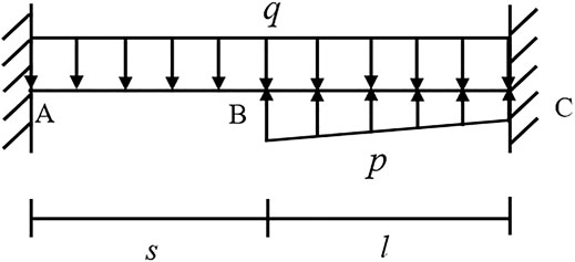
FIGURE 5. The undisturbed segment is not considered.
The boundary conditions are as follows: when x = 0,
When the tunnel is excavated to the end of the pipe-roof, due to the excavation of the lower rock body, the end of the pipe-roof hangs in the air. Most of the length of the pipe-roof has been pre-reinforced in the stratum. The suspended section is equivalent to a cantilever. The beam, based on the Winkler elastic foundation beam model, considers the delay effect of the initial support and the disturbance area in front of the tunnel. The pipe-roof model is established as shown in Figure 6. The pipe-roof is simplified to the elastic foundation beam, and the second lining is considered to have played a role. Point A is regarded as the fixed end, the tunnel face is closer to the front end of the pipe-roof, and point C is located within the influence range of the tunnel excavation and regarded as the free end.
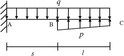
FIGURE 6. Dig to the end.
The boundary conditions are as follows: when x = 0,
The unified model is based on the existing pipe-roof model, which considers the arch effect of the pipe-roof, combined with the mechanical model of the pipe-roof when the tunnel is excavated to the end. It can be obtained by comparing the three models. The calculation length and boundary conditions of the model are different, but the unified model proposed in this paper can be simplified into the other two models according to engineering needs, and the factors considered are more comprehensive.
Example Calculation
Through specific engineering examples, three models are used to calculate deflection, bending moment, and shear force and are compared with the data of numerical simulation and actual monitoring to verify the rationality of the model.
Deflection
The total length of the Erlang Mountain Tunnel is 4,160.0 m, and the tunnel section is large, and the geological conditions are poor. In order to ensure the safe construction of the tunnel entrance, the tunnel exit section is supported in advance by a pipe-roof. The overburden thickness of the tunnel is 10.0 m, the excavation height is 7.0 m, the diameter of the steel pipe is 102 mm, the thickness is 10.0 mm, the length is 30.0 m, the transverse installation spacing is 40.0 cm, the elastic modulus of the steel pipe is 200.0 GPa, the internal friction angle of the surrounding rock is 30°, and the unit weight of the surrounding rock is 22.0 kN/m3 (Jia et al., 2010). The three models were, respectively, used for calculation, and the calculated deflections are shown in Figure 7.
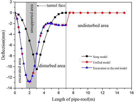
FIGURE 7. The deflection of the steel pipe in the pipe-roof.
Three models’ calculations in Figure 7 show that the change trend of the deflection curve is similar to that in the excavation, which has not been reaching the maximum supporting area. The pipe-roof completely assumes the overlying load current of the surrounding rock, the pipe-roof is in a bad condition, and the disturbed area, due to the calculation of the length and the different boundary conditions, causes the variation of the three models. When the tunnel is excavated to the end, the end of the pipe-roof is regarded as the free end, so the deflection does not tend to be zero at the end, indicating that the selection of the remaining length of the pipe-roof in front of the tunnel face has a significant influence on the effect of the pipe-roof when the tunnel is excavated to the end. The model of excavation to the end is almost consistent with the deflection curves of the unified model at the excavation and disturbed sections, which indicates that the unified model can be simplified to the model of excavation to the end.
Birgl tunnel is a classic case of domestic and foreign scholars studying the mechanical behavior of pipe-roof (Oke, 2016; Oke et al., 2016). The key Birgl tunnel parameters are listed as follows: the buried depth of the tunnel is 30–50 m, diameter of the steel pipe is 114.0 mm, wall thickness is 6.3 mm, transverse installation spacing is 40.0–50.0 cm, and cohesion is 0.03–0.06 MPa. (Oke, 2016). The calculation results of the three models were compared with the field measured values and Oke’s model (Oke, 2016), as shown in Figure 8.
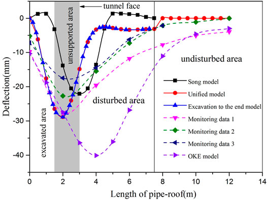
FIGURE 8. The deflection of the steel pipe in the pipe-roof.
As shown in Figure 8, the maximum deflection values calculated by the three models appear behind the tunnel face, which are close to the position and value of the measured maximum values, indicating that the three models are reasonable to a certain extent. However, near the right end of the support, the deflection of the Song model is positive, indicating the phenomenon of upper arching of the steel pipe of the pipe-roof. Considering the undisturbed section, the disturbance tends to zero, and the steel pipe does not appear upper arching. It shows that considering the undisturbed section can solve the problem of the upper arch of pipe-roof to a certain extent. The deflection curves of the model excavated to the end are the same as those of the model considering the undisturbed section in the excavation area and the disturbed area. This is because the calculation formulas of the first two sections are the same. If the undisturbed section is considered, the disturbance will gradually approach zero with the increase of the length of the pipe-roof, which is consistent with the results of the monitored values and more in line with the actual situation.
Through the comparison of several models, it is found that the unified model is closer to the actual monitoring results, which can better reflect the real mechanical properties of the pipe-roof and can effectively solve the phenomenon of the upper arch of pipe-roof. In order to study the influence of the residual length of the pipe-roof on the deflection when the excavation reaches the end, only the boundary condition of the unified model needs to be changed and the length of the disturbed section needs to be adjusted.
Bending Moment and Shear Force
A subway tunnel in South Korea, which is located below the surface of weathered rock, is excavated. The buried depth of the tunnel is 20.0 m, excavation height is 5.0 m, diameter of the steel pipe is 114.3 mm, thickness is 5.6 mm, transverse installation spacing is 40.0 cm, elastic modulus of steel pipes E = 210.0 GPa, internal friction angle of surrounding rock φ = 30°, and the unit weight of surrounding rock γ = 21.0 kN/m3(Song, 2013). The bending moment and shear force calculated by the three models are shown in Figures 9, 10, and the results are compared and analyzed with the actual monitored values and the results calculated by MIDAS numerical simulation.
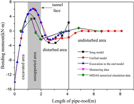
FIGURE 9. The bending moment of the steel pipe in the pipe-roof.
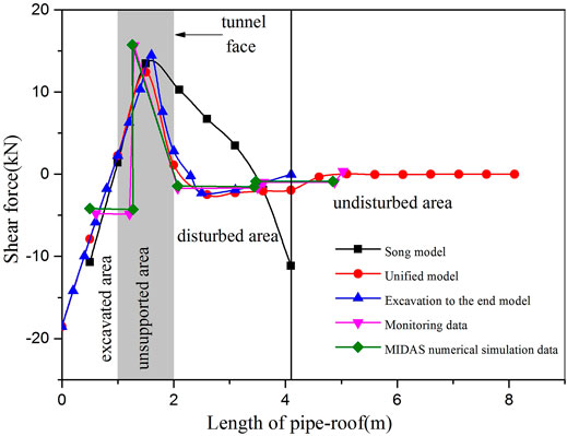
FIGURE 10. The shear force of the steel pipe in the pipe-roof.
According to Figure 9, the three models are consistent with the actual monitored values and the bending moment curve calculated by numerical simulation, indicating that the models are reasonable to a certain extent. The maximum bending moments all appear behind the tunnel face during tunnel excavation, that is, the excavated section without support. In the disturbed area, the bending moments gradually decrease, while in the undisturbed area, the bending moments gradually approach zero, indicating that the pipe-roof can effectively control the deformation of surrounding rock.
The maximum bending moment of the Song model also appears behind the tunnel face, but in the region of the disturbance, the bending moment increases with the decrease of the first, and the results are quite different from those of the other two models. This is mainly due to the disturbance area calculation length to the end and setting it as the fixed end, but the truth is it is not strictly a fixed end. The bending moment outside the disturbance area will continue to pass. Therefore, the bending moment value of the model increases in the disturbed area, and the phenomenon of upper arch appears.
As shown in Figure 10, the variation trend of the three models is consistent with the actual monitored data and the shear curve calculated by numerical simulation, indicating that the models are reasonable to a certain extent. In the unified model and the model excavated to the end, the shear force has a maximum value behind the tunnel face, that is, the excavated section without support. In the vicinity of the tunnel face, the shear force suddenly changes from positive to negative. In the disturbed area, the shear force gradually decreases, while in the undisturbed area, the shear force gradually approaches zero. The three models regard the two ends of the support as fixed ends, so there is a large shear force at the left end of the support. Without considering the undisturbed section of the curve and the other two models have bigger difference, shear at the end of the disturbed area appeared more negative because the model disturbance area is taken as a fixed end. At the end, the load outside the disturbance area will continue to be released, considering the undisturbed section in front of the constraints and conforming to the actual situation.
Through the concrete analysis of the three cases, the three models in this study are compared with other models, the actual monitoring data, and the calculated values of numerical simulation, and it shows that the three models are reasonable to a certain extent. The unified model can better reflect the mechanical behavior of the pipe-roof. It can not only solve the phenomenon of the pipe-roof arching at the end of the disturbed section but also choose the reasonable remaining length of the pipe-roof by changing the length of the disturbed section when the tunnel is excavated to the end.
The maximum value of deflection, bending moment, and shear force calculated by the unified model appears in the excavated and unsupported section behind the tunnel face. In the undisturbed region, it gradually becomes zero, and the pipe-roof can effectively pass near the constraints of the upper load without excavation area, which can effectively control the deformation of the tunnel and ensure the stability of the constraints during tunnel excavation. The arch effect of the pipe-roof formed by pipe-roof grouting is considered and the calculated maximum deflection is smaller than that of other models.
Through the calculation of several models, the results show that the unified model can be simplified to the model when the excavation is to the end of the model without considering the undisturbed section. Therefore, the boundary conditions of the unified model can be adjusted for different situations.
Parameter Analysis
The protective effect of pipe-roof is related to the design of pipe-roof parameters, stratum parameters, and the way of tunnel excavation. However, for a specific tunnel project, the buried depth, surrounding rock level, and physical and mechanical parameters of the tunnel are generally determined. Therefore, the influence of the excavation footage, diameter, and elastic modulus of the grouting convergence area on the deformation and force of the pipe-roof is generally considered.
Excavation Footage
When the elastic modulus of the surrounding rock is Eg = 4 × 10⁸ N/m2, the elastic modulus of the convergence area is Ec = 1 × 10⁷ N/m2. The load q = 220 kN/m2, the diameter of the steel pipe is 89 mm, and the excavation footage is 1, 1.25, 1.5, 1.75, and 2 m, respectively. The deflection and bending moment curves of the pipe-roof are drawn, respectively, as shown in Figure 11. The influence of excavation footage on the deflection and bending moment of the pipe-roof is analyzed.
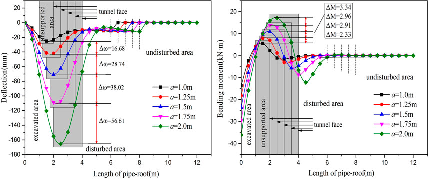
FIGURE 11. The relation between excavation footage and deflection and bending moment when the diameter is 89 mm.
It is shown in Figure 11 that the deflection and bending moment of the pipe-roof are positively correlated with the excavation footage. With the increase of excavation footage, the deflection and bending moment also increase. When the excavation footage is 1, 1.25, 1.5, 1.75, and 2 m, the deflection of the pipe-roof increases by 66% and 68, 54, 52%, and the bending moment increases by 42%, 37, 27, and 24%, respectively, with the increase of each excavation footage. When the excavation footage a = 1.5 m, the maximum deflection of the steel pipe is 2.8 times that of the steel pipe when a = 1 m, and when the excavation footage a = 2 m, the maximum deflection of the steel pipe is 6.5 times that of the steel pipe when a = 1 m, indicating that with the gradual increase of the excavation footage, the deflection deformation of the steel pipe is gradually larger.
In the process of tunnel excavation, the deflection curve of the pipe-roof becomes grooves, and the grooves of the curve gradually move forward and down along with the advance of the tunnel face. The maximum value appears behind the tunnel face, that is, the excavated section without support, indicating that the pipe-roof can transfer the load and pressure on the surrounding rock to the nearby tunnel face. In the disturbed section in front of the tunnel face, the deflection decreases gradually, while in the undisturbed section, the deflection tends to zero, which indicates that the pipe-roof can effectively control the deformation of surrounding rock and play a supporting role in advance. The bending moment also increases with the increase of the excavation footage, and the maximum positive bending moment appears behind the face of the tunnel, and the maximum negative bending moment appears in front of the face of the tunnel, indicating that the pipe-roof can effectively bear the bending moment after tunnel excavation, and the bending moment borne by the pipe-roof gradually increases with the increase of the excavation footage.
The Diameter
When the elastic modulus of surrounding rock is Eg = 4 × 10⁸ N/m2, the load q = 220 kN/m2, the excavation footage is 1.5 m, and the diameters are 89, 102, 108, 114, and 159 mm, the deflection and bending moment curves of the pipe-roof are drawn, respectively, as shown in Figure 12. The influence of the diameter of the steel pipe on the deflection and bending moment of the pipe-roof is analyzed.
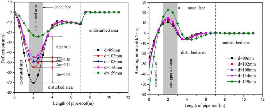
FIGURE 12. The relation between diameter and deflection and bending moment.
As can be seen in Figure 12, the deflection is negatively correlated with the diameter of the steel pipe, while the bending moment is positively correlated with the diameter of the steel pipe. When the diameters of the steel pipes are 89, 102, 108, 114, and 159 mm, the deflection decreases by 23% 10, 9, and 46%, and the bending moment increases by 19% 8, 7, and 52%, respectively, indicating that when the diameters of the steel pipes are 108 and 114 mm, the effect of the steel pipe is similar. When considering economic factors, it is more economical to choose a steel pipe with a diameter of 108 mm. When the condition of surrounding rock is poor, choosing large diameter can better control the deformation of surrounding rock. The size of the diameter of the steel pipe affects the stiffness of the pipe-roof, that is, the diameter of the steel pipe, and the stiffness of the pipe-roof is large, which will affect the bending stiffness of the pipe-roof. The bending stiffness is large, and the deflection of the steel pipe becomes smaller and the bending moment becomes larger under the action of the surrounding rock load. When the diameter of the steel pipe is the largest, the bending moment it bears is also the largest, indicating that after tunnel excavation, the larger the diameter of the steel pipe is, the greater the pressure of the upper surrounding rock will be. In front of the tunnel face, the bending moment is negative, that is, the direction is vertical and downward, mainly because the pipe-roof in this section has played a role to bear them pressure of the overlying surrounding rock. In the excavated area behind the tunnel face, the bending moment of the pipe-roof has both negative and positive values. The main reason for the positive and negative values is that the pipe-roof can interact with the initial support and jointly bear the load pressure of the surrounding rock.
Elastic Modulus of the Convergence Area
Considering the elastic modulus of the convergence area, that is, considering the arch effect of the whole pipe-roof arch formed by pipe-roof grouting, the elastic modulus of different sizes of the convergence area was selected to analyze the influence of the elastic modulus of the convergence area on the deflection and bending moment of the pipe-roof.
When the elastic modulus of the surrounding rock is Eg = 4 × 10⁸ N/m2 and the elastic modulus of the convergence area is Ec = 1 × 10⁷ N/m2, Ec = 4 × 10⁸ N/m2, and Ec = 4 × 10⁹ N/m2, the tunnel excavation footage and the deflection and bending moment curves of the pipe-roof under different diameters are drawn, as shown in Figure 13.
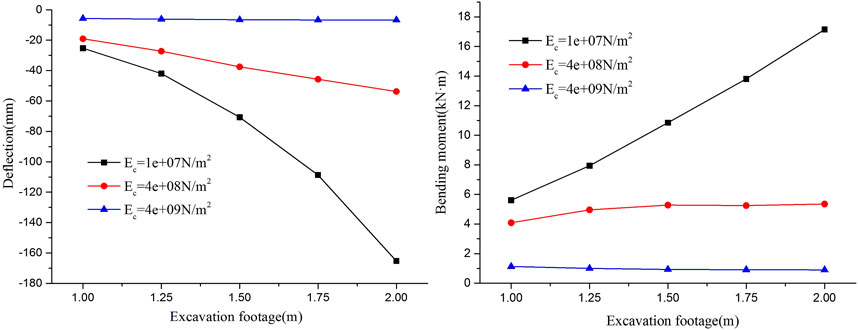
FIGURE 13. When the diameter is 89 mm, the relation between excavation footage and deflection and bending moment under different elastic moduli of convergence area.
It can be seen from Figure 13 that the deflection and bending moment of the pipe-roof gradually decrease with the increase in the elastic modulus of the convergence area. When the elastic modulus of the convergence area is Ec = 1 × 10⁷ N/m2, the deflection and bending moment of the pipe-roof increase with the increase of excavation footage, and the increase range is very large. When the elastic modulus of the convergence area is Ec = 4 × 10⁹ N/m2, that is, Ec = 40Eg, and the excavation footage increases from 1 to 2 m, the deflection and bending moment of the steel pipe do not increase much, indicating that the deflection and bending moment of the steel pipe do not change much with the change of excavation footage when the elastic modulus of the convergence area is much larger than that of the surrounding rock. It shows that the elastic modulus of the reinforcement area has a greater impact on the deflection and bending moment of the steel pipe. The elastic modulus of the reinforcement area is related to the grouting effect of the pipe-roof and the spacing of the pipe-roof. Therefore, in the actual project, changing the excavation footage is not the most effective way to reduce the deflection and bending moment of the pipe-roof. The grouting effect of the pipe-roof should be optimized and the spacing of the steel pipe should be arranged reasonably. When Ec > 40Eg, choosing the larger excavation footage can realize the safe and fast construction of the large excavation footage of the pipe-roof and save the construction period.
When the excavation footage is 1.5 m, the elastic modulus of surrounding rock is Eg = 4 × 10⁸ N/m2, and the elastic modulus of convergence area is Ec = 1 × 10⁷ N/m2, Ec = 1 × 10⁸ N/m2, Ec = 4 × 10⁸ N/m2, Ec = 1 × 10⁹ N/m2, Ec = 4 × 10⁸ N/m2, Ec = 4 × 10⁹ N/m2, and Ec = 4 × 10⁹ N/m2. The curve of diameter, deflection, and bending moment are drawn, as shown in Figure 14.
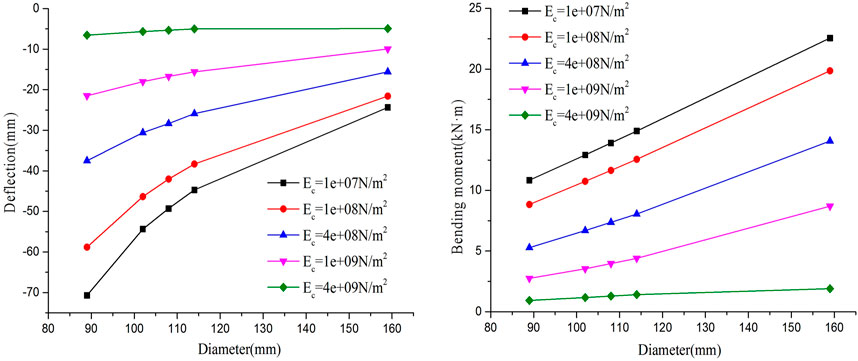
FIGURE 14. The relation between the diameter of the steel pipe and deflection and bending moment under different elastic moduli of reinforcement.
It can be seen from Figure 14 that the deflection and bending moment of the pipe-roof decrease with the increase in the elastic modulus of the convergence area. When the elastic modulus of the reinforced area is less than that of the surrounding rock, the deflection and bending moment of the pipe-roof are relatively large. When the elastic modulus of the reinforced area is much larger than that of the surrounding rock, the deflection and bending moment of the pipe-roof have small values. When the diameter is 89 mm, the elastic modulus of the convergence area increases from 1 × 10⁷ N/m2 to 4 × 10⁸ N/m2, and the deflection and bending moment are reduced by 47 and 51%, respectively. When the elastic modulus of the convergence area increases from 4 × 10⁸ to 4 × 10⁹ N/m2, the deflection and bending moment of the pipe-roof decrease by 83 and 82%. It shows that the deformation of surrounding rock can be effectively controlled when the elastic modulus of the convergence area is much larger than that of surrounding rock. The deflection of the pipe-roof decreases with the increase in the diameter of the steel pipe, and the bending moment of the pipe-roof increases with the increase in the diameter of the steel pipe. When the elastic modulus of the convergence area is Ec = 1 × 10⁷ N/m2 and Ec = 4 × 10⁹ N/m2, respectively, and the diameter of steel pipe increases from 89 to 159 mm, the deflection decreases by 66 and 25%, and the bending moment increases by 108 and 104%, respectively. Results show that the diameter of the change on the influence of deflection is bigger, when the elastic modulus of the reinforced area is greater than the surrounding rock elastic modulus, thus increasing the diameter of steel pipe, and the pipe-roof deflection of change is very small. In actual engineering, simply increasing the diameter of steel pipe cannot effectively control the deformation of the surrounding rock. Increasing the elastic modulus of convergence area can significantly improve the advanced pre-support effect of pipe-roof.
Remaining Length of Pipe-Roof in Surrounding Rock
For the remaining length of the pipe-roof in the surrounding rock when the tunnel face is close to the front end of the pipe-roof, calculate the deflection and bending moment curve of the pipe-roof when the remaining length of the pipe-roof is 1.0 m, 1.5 m, 2.0 m, 2.5 m, 3.0 m and 4.0 m, as shown in Figure 15, so as to determine the most economical reserved length at the end of the pipe-roof construction on the premise of ensuring safety.
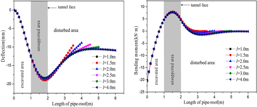
FIGURE 15. The deflection and bending moment curves of the pipe-roof with different remaining lengths.
As can be seen in Figure 15, the maximum deflection and its position are situated near the constraints, suggesting that during tunnel excavation, the pipe-roof can effectively bear the overlying load of surrounding rock, as the growth of the pipe-roof in the remaining length of the surrounding rock, the deflection curve is more and more gentle, shows that the longer the residual length of pipe-roof in the surrounding rock, the safer is tunnel excavation. The change of bending moment is not very significant. Under different residual lengths, the maximum bending moment and the position of the pipe-roof are all near the tunnel face. Considering the economic factors, it is most economical to choose the residual length of 2–3 m in the surrounding rock.
Conclusion
In this study, a unified elastic foundation beam model for pipe-roof was proposed by combining the elastic foundation beam model considering the arch effect with the model during excavation to the end. Through a specific case, the three models were compared and analyzed, and the unified model was taken as an example to analyze the influence of different parameters on the stress and deformation of pipe-roof. The main conclusions were as follows:
1) Through the specific case analysis, three kinds of model and the results are consistent with field monitoring data, showing that the three kinds of model can better reflect the pipe-roof mechanical behavior, and the unified model in this paper can solve the arch up phenomenon of steel pipe at the end of disturbed area; owing to the strong practicability of the model, changing the boundary conditions of the model can calculate the actual stress of the pipe-roof when the tunnel is excavated to the end.
2) Unified model calculated the maximum deflection, bending moment, and shear force in excavation, which has not been supporting in the behind of the constraints. In the undisturbed region, it gradually becomes zero so that the pipe-roof can effectively pass near the constraints of the upper load without the excavation area, which can effectively control the deformation of the tunnel and ensure the stability of the constraints during tunnel excavation.
3) Through the analysis of the pipe-roof parameters, it is found that the deflection and bending moment of the pipe-roof are positively correlated with the excavation footage. The deflection of the pipe-roof is negatively correlated with the diameter of the steel pipe, while the bending moment is positively correlated with the diameter of the steel pipe. Therefore, it is more economical to choose the steel pipe with smaller excavation footage and 108 mm during construction.
4) When Ec = 40.0Eg, the excavation footage and diameter of steel pipe have little influence on the deflection and bending moment of the pipe-roof. Therefore, simply changing the excavation footage and diameter of the steel pipe has little influence on the mechanical properties of the pipe-roof. Increasing the elastic modulus of the convergence area is an effective method to reduce the deflection and internal force of the pipe-roof.
5) When the tunnel is excavated to the end of the pipe-roof, the longer the residual length of the pipe-roof in the surrounding rock, the safer the tunnel will be during excavation. The economically reasonable value of the residual length of the pipe-roof in the surrounding rock is 2–3 m.
Data Availability Statement
The original contributions presented in the study are included in the article/Supplementary Material, further inquiries can be directed to the corresponding author.
Author Contributions
ZS proposed the model; XX and XT calculated the model; HL and GZ analyzed the data; and XX wrote the paper. All authors read and approved the final manuscript.
Funding
The present work was subsidized and supported by the National Natural Science Foundation of China (Nos. 52178393 and 51578447), the Science and Technology Innovation Team of the Shaanxi Innovation Capability Support Plan (No. 2020TD-005), and the Science and Technology Development Program of the Shaanxi Provincial Department of Housing and Urban‐Rural Construction (No. 2019-K39).
Conflict of Interest
Author GZ was employed by the company China Railway Major Bridge Engineering Group.
The remaining authors declare that the research was conducted in the absence of any commercial or financial relationships that could be construed as a potential conflict of interest.
Publisher’s Note
All claims expressed in this article are solely those of the authors and do not necessarily represent those of their affiliated organizations, or those of the publisher, the editors and the reviewers. Any product that may be evaluated in this article, or claim that may be made by its manufacturer, is not guaranteed or endorsed by the publisher.
Acknowledgments
The authors gratefully acknowledge the financial support.
Supplementary Material
The Supplementary Material for this article can be found online at: https://www.frontiersin.org/articles/10.3389/feart.2022.803670/full#supplementary-material
References
Aksoy, C. O., and Onargan, T. (2010). The Role of Umbrella Arch and Face Bolt as Deformation Preventing Support System in Preventing Building Damages. Tunnelling Underground Space Tech. 25 (5), 553–559. doi:10.1016/j.tust.2010.03.004
Chang, S. (1999). Research on Pre-brace Mechanism of Pipe Umbrella Method. Chengdu(Sichuan): Southwest Jiaotong University. [Doctoral thesis].
Chen, F., Wang, L., and Zhang, W. (2019). Reliability Assessment on Stability of Tunnelling Perpendicularly beneath an Existing Tunnel Considering Spatial Variabilities of Rock Mass Properties. Tunnelling Underground Space Tech. 88 (6), 276–289. doi:10.1016/j.tust.2019.03.013
Han, L., Liu, H., Zhang, W., Ding, X., Chen, Z., Feng, L., et al. (2021). Seismic Behaviors of Utility Tunnel-Soil System: With and without Joint Connections. Underground Space (6), 1–14.
Jia, J., Wang, H., Tu, B., and Meng, G. (2010). Analytical Analysis and Field Test of Mechanical Behavior of Pipe-Roof. Rock Soil Mech. 31 (6), 1858–1864.
Li, J., Tan, Z., Yu, Y., and Ni, L. (2011). Analysis of Deformation Monitoring and Mechanical Behaviors of Big Pipe- Roof for Shallow-Buride Large-Span Tunnel to Underpass Highway. Chin. J. Rock Mech. Eng. 30 (1), 3002–3008.
Miwa, M., and Ogasawara, M. (2005). Tunnelling through an Embankment Using All Ground Fasten Method. Tunnelling Underground Space Tech. 20 (2), 121–127. doi:10.1016/j.tust.2003.12.001
Ocak, I. (2008). Control of Surface Settlements with Umbrella Arch Method in Second Stage Excavations of Istanbul Metro. Tunnelling Underground Space Tech. 23 (6), 674–681. doi:10.1016/j.tust.2007.12.005
Oke, J. (2016). Determination of Nomenclature, Mechanistic Behaviour, and Numerical Modelling Optimization of Umbrella Arch Systems. [Kingston(Ontario)]: Queen’s University. [Doctoral thesis].
Oke, J., Vlachopoulos, N., and Diederichs, M. S. (2016). Semi-analytical Model for Umbrella Arch Systems Employed in Squeezing Ground Conditions. Tunnelling Underground Space Tech. 56, 136–156. doi:10.1016/j.tust.2016.03.006
Singh, B., Viladkar, M. N., Samadhiya, N. K., and Sandeep, F. (1995). A Semi-empirical Method for the Design of Support Systems in Underground Openings. Tunnelling Underground Space Tech. 10 (3), 375–383. doi:10.1016/0886-7798(95)00016-r
Song, K.-I., Cho, G.-C., Chang, S.-B., and Lee, I.-M. (2013). Beam-spring Structural Analysis for the Design of a Tunnel Pre-reinforcement Support System. Int. J. Rock Mech. Mining Sci. 59 (5), 139–150. doi:10.1016/j.ijrmms.2012.12.017
Song, Z., Dong, L., Tao, L., Zhao, X., and Zhang, Y. (2020b). Research on Calculation Method for Stress and Deformation of Transverse Pipe Roof in Subway Station with Rectangular Cross-Section Based on Transfer Matrix. Tunnel Construction 40 (12), 1733–1741.
Song, Z., Tian, X., Zhou, G., and Li, W. (2020a). Theoretical Analysis of Advanced Pre-support and Maintenance Behavior of Pipe-Roof in Tunnel. China J. Highways Transport 33 (4), 89–98.
Wang, D., Yuan, J., Li, J., Peng, X., Wu, Z., Liu, W., et al. (2017). Deformation Prediction and Engineering Application of Pipe-Roof in Shallow Buried Soft Hole Section Considering Construction Characteristics. J. Rock Mech. Eng. 36 (3), 716–724.
Wang, D., Yuan, J., Wang, J., Wang, K., Xia, Y., Wang, H., et al. (2019). Deformation Prediction and Parameter Sensitivity Analysis of Pipe Roof in Shallow Soft Rock Tunnels Considering Construction Process. Mod. Tunnelling Tech. 56 (1), 79–86.
Wang, X., Shi, J., Chai, L., Han, X., and Hu, Q. (2018). Construction Method Optimization Study on Weak Surrounding Rock of Shanziding Highway Tunnel. J. Underground Space Eng. 14 (S1), 185–192.
Wu, J., and Song, W. (2007). Machallical Analysis on Pipe Roof Advaned Support in Shallow Excavation. Geotrchnical Eng. Techique 21 (3), 116–121.
Wu, S., Tang, H., Luo, H., Dai, Y., and Wu, Z. (2019). Research on Supporting Mechanism and Engineering Application of Advanced Pipe-Roof in Shallow Buried Soft Rock Highway Tunnel. J. Rock Mech. Eng. 38 (S1), 3080–3091.
Xiang, Y., Liu, H., Zhang, W., Chu, J., Zhou, D., and Xiao, Y. (2018). Application of Transparent Soil Model Test and DEM Simulation in Study of Tunnel Failure Mechanism. Tunnelling Underground Space Tech. 74 (4), 178–184. doi:10.1016/j.tust.2018.01.020
Xiao, S., Xia, C., Zhu, H., Li, X., and Liu, X. (2006). Vertical Deformation Prediction on Upper Pipe-Roof during a Box Culvert Being Pushed within a Pipe-Roof. J. Rock Mech. Eng. 25 (9), 1887–1892.
Keywords: tunnel engineering, pipe-roof, elastic foundation beam, mechanical model, parameter analysis
Citation: Xu X, Song Z, Li H, Tian X and Zhou G (2022) Unification of the Mechanical Model and Parameter Analysis of the Elastic Foundation Beam of Pipe-Roof. Front. Earth Sci. 10:803670. doi: 10.3389/feart.2022.803670
Received: 28 October 2021; Accepted: 18 March 2022;
Published: 25 April 2022.
Edited by:
Chenghua Shi, Central South University, ChinaReviewed by:
Siyuan Ma, China Earthquake Administration, ChinaWengang Zhang, Chongqing University, China
Copyright © 2022 Xu, Song, Li, Tian and Zhou. This is an open-access article distributed under the terms of the Creative Commons Attribution License (CC BY). The use, distribution or reproduction in other forums is permitted, provided the original author(s) and the copyright owner(s) are credited and that the original publication in this journal is cited, in accordance with accepted academic practice. No use, distribution or reproduction is permitted which does not comply with these terms.
*Correspondence: Zhanping Song, songzhpyt@xauat.edu.cn