Characterization of Physical Field and Flow Assurance Risk Analysis of Subsea Cage-Sleeve Throttling Valve
 Donglei Jiang1
  Youwei Zhou
 Yonghai Gao
- 1Engineering and Technology Operating Center, Zhanjiang Branch of CNOOC Ltd, Zhanjiang, China
- 2School of Petroleum Engineering, China University of Petroleum(East China), Qingdao, China
The subsea production system is presently widely adopted in deepwater oil and gas development. The throttling valve is the key piece of equipment of the subsea production system, controlling the safety of oil and gas production. There are many valves with serious throttling effect in the subsea X-tree, so the hydrate formation risk is relatively high. In this work, a 3D cage-sleeve throttling valve model was established by the numerical simulation method. The temperature and pressure field of the subsea throttling valve was accurately characterized under different prefilling pressure, throttling valve opening degree, and fluid production. During the well startup period, the temperature of the subsea pipeline is low. If the pressure difference between the two ends of the pipeline is large, the throttling effect is obvious, and low temperature will lead to hydrate formation and affect the choice of throttling valve material. Based on the analysis of simulation results, this study recommends that the prefilling pressure of the subsea pipe is 7–8 MPa, which can effectively reduce the influence of the throttling effect so that the downstream temperature can be kept above 0°C. At the same time, in regular production, a suitable choke size is opened to match the production, preventing the serious throttling effect from a small choke size. According to the API temperature rating table, the negative impact of local low temperature caused by the throttling effect on the temperature resistance of the pipe was considered, and the appropriate subsea X-tree manifold material was selected to ensure production safety. The hydrate phase equilibrium curve is used to estimate the hydrate formation risk under thermodynamic conditions. Hydrate inhibitors are injected to ensure downstream flow safety.
Introduction
In 1947, American engineers first proposed the concept of a “subsea wellhead” (Li and An, 2020), which laid the foundation for the development of a subsea production system. At present, subsea production systems are widely used in deep-water oil and gas fields, such as offshore Brazil and the south China sea (Hong et al., 2018). With further research and a full understanding of production conditions, the technologies and equipment of subsea production systems will play a dominant role in the future of deepwater oil and gas development.
The subsea X-tree is the key equipment in the subsea production system to control oil and gas production safety. The stable opening and closing of the valve in the X-tree play a role in oil and gas production. Valve flow capacity is mainly evaluated by Cv value, and different internal structure has different Cv value (Grace and Frawley, 2011). Only by knowing the valve internal structure can an engineer accurately judge the flow capacity of the valve. From the onshore experience, valves are vulnerable to fluid erosion, so a lot of researches have focused on the problem of sand erosion and throttling valves (Gharaibah and Zhang, 2015). However, in valves, chokes, and jumper bent pipelines on the wing of the subsea X-tree (Zhao et al., 2014), the oil and gas flow turbulence is intensified, with serious throttling effect, so the temperature and pressure drop is obvious. At the same time, the low temperature at the seabed further aggravates the risk of hydrate formation. On site, hydrate inhibitors are often injected to ensure stable production. Furthermore, the subsea chokes confront the fluid erosion and the low temperature of throttling effect, which has certain requirements for the temperature resistance of the pipe material. Based on the requirements of offshore flow assurance, researchers need to study the temperature and pressure field under different production conditions (Sotoodeh, 2019).
Compared with onshore oil and gas development, offshore operations are more difficult and have high cost and technical requirements. Subsea production equipment cannot be replaced as easily as onshore. The numerical simulation method is adopted to provide a relevant basis for the reliability of the equipment. Cameron, FMC, and others possess the majority of the subsea X-tree, subsea throttling valves, and related equipment market share (Rassenfoss, 2011). The internal structure of subsea equipment is very complicated, so there are few studies on 3D simulation of real objects at present. When simulating the physical field of subsea throttling valves, scholars usually use a 2D variable diameter model instead of a 3D cage-sleeve model to describe the throttling effect at the throttling valve. In order to accurately characterize the physical field at the cage-sleeve throttling valve, a 3D cage-sleeve throttling valve model is established in this study.
This study characterizes the temperature and pressure distribution of the subsea chokes, the main throttling part of the subsea X-tree. We assess downstream temperature and hydrate formation risk for different gas production and valve opening degree. In the well startup period, if the pressure difference between the throttling valve ends is too large, the throttling effect is very obvious (Ju et al., 2021). Throttle valve opening degree and production should be a good match. At last, the prefilling pressure of downstream sea pipe is analyzed and the reasonable pressure design value is recommended. To avoid hydrate formation, hydrate inhibitors are often injected to ensure safe production.
Joule-Thomson Effect of Subsea Throttling Valve
The subsea throttling valve plays the role of controlling and regulating the flow in the subsea production system. When the gas flows through the throttling valve, the flow area decreases, and turbulence increases (Zhang et al., 2010). The dominant control function is the small hole in the throttling valve cage. The internal flow channel of a single throttling hole is shown in Figure 1.
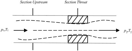
FIGURE 1. Throttling schematic diagram of the internal flow channel of a single throttling hole.
The Joule-Thomson effect, also known as the throttling effect, occurs when gas passes through the orifice, which is the main cause of the low temperature of the throttling valve. After the natural gas passes through the throttling valve, the pressure drops, and the expansion of the gas needs to absorb heat, leading to the temperature drop in downstream of the choke. The lower the downstream pressure, the more obvious the temperature drop. Generally speaking, when natural gas reaches the throttle valve, both the temperature and pressure will drop under the Joule-Thomson cooling effect. The ratio of the change of temperature and pressure in isoenthalpy is usually expressed as the Joule-Thomson coefficient, or throttling expansion coefficient (Shoghl et al., 2020):
According to Eq. 1, the throttling temperature drop caused by pressure drop can be calculated by Eq. 2 after transpose integration:
Different gases have different values of Joule-Thomson coefficient under different temperatures and pressures. This study simulates the Joule-Thomson coefficient under different temperatures and pressures for pure methane gas, and the specific values are shown in Figure 2. It can be seen that the higher the gas temperature and pressure is, the lower the CJ-T value is, indicating that the gas throttling effect is weak under high temperature and high pressure. The CJ-T value is about 1.5°C/MPa at 20 MPa and about 2.7–3.7°C/MPa at 10 MPa. If the gas pressure drops from 20 to 10 MPa, according to Eq. 2, the temperature drop range affected by the throttling effect is 15.0–37.0°C.
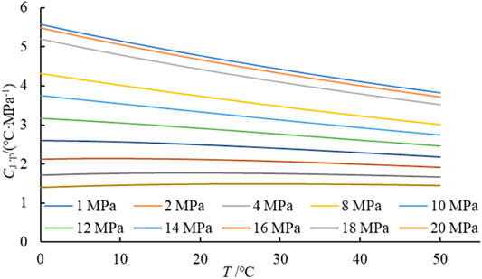
FIGURE 2. Reference values of J-T coefficients under different temperature and pressure.
In real production, a reasonable development plan needs to be adopted. In the throttling process of natural gas, there are two flow states: critical flow and subcritical flow. Under the critical flow state, the pressure fluctuation generated at the downstream cannot affect the upstream pressure through the throttling valve (Zheng et al., 2020). However, the pressure difference between the two ends of the throttling valve is large, so the negative impact of the large throttling effect should be considered comprehensively.
Critical pressure ratio is commonly used to divide critical flow state and subcritical flow. The critical pressure ratio is defined as:
Where, κ is the adiabatic index of natural gas, dimensionless; The κ value is a function of temperature and pressure and is closely related to gas properties. When the downstream pressure to upstream pressure ratio is less than the critical pressure ratio, production through the valve will not change. Production and pressure ratio are illustrated in Figure 3.
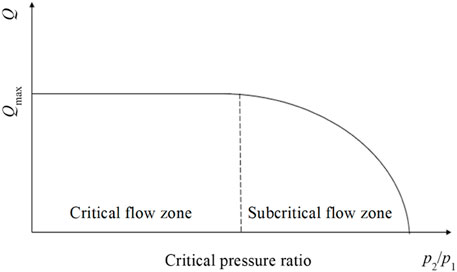
FIGURE 3. Relation graph of natural gas pressure ratio and production.
Generally, scholars believe that when the pressure after throttling is about half of the pressure before throttling, the critical flow state can be reached. In the critical flow state, there is a maximum critical flow qmax. Eq. 4 is the calculation formula of gas critical flow production in a single hole:
Where, qmax is the volume flow of gas in standard condition, 104 m3 d−1; p1 is the upstream pressure, MPa; p2 is downstream pressure, MPa; d is the diameter of the choke hole, mm; and γg is the relative density of the gas. T1 is the throttling valve inlet temperature, K; Z1 is the gas compression factor at the inlet of the throttling valve; κ is the adiabatic index of the gas, κ = cp/cv.
When natural gas is in a subcritical flow state, the formula of gas flow in a single hole is as follows:
According to the above two formulas, when the economic production range is determined, a reasonable size of single-hole choke can be estimated. Considering the number of holes and their distribution, an appropriate throttling valve can be preliminarily selected. When the flow is in the subcritical flow state, the flow rate varies with the pressure difference between the two ends of the throttling valve. Therefore, it is more necessary to adjust the throttling valve size to match different production procedures.
Geometric Model and Meshing
The cage-sleeve throttling valve is a commonly used choke type in the subsea production system. Compared with needle valves and orifice valves, the cage-sleeve throttling valve has a symmetrical distribution of throttling holes. When the gas passes through a throttling hole, it is a mutual hedge to consume energy. This structure improves the gas flow field distribution in the throttling valve so that the production is more stable.
This study designs a 3D cage-sleeve throttling valve model using Solidworks, and its structure is shown in Figure 4. The core parts of the cage-sleeve throttling valve are the cage sleeve and the plunger. Its working principle is to control the movement of the internal plunger through the stem, then the plunger covers the cage-sleeve holes to adjust the flow area (Malavasi and Messa, 2014), directly affecting the flow ability of the throttling valve, and finally achieving the purpose of throttling. The pipe inner diameter in the inlet and outlet of this model is 4 ″1/2 (114 mm). Each row of the throttling holes is arranged in parallel along the axis of the cage-sleeve and has an angle of 60° along the circumference. The number of holes in each row is 5, so the total number of throttling holes is 30. Large holes meet the requirements of high production and small holes can flow low production.
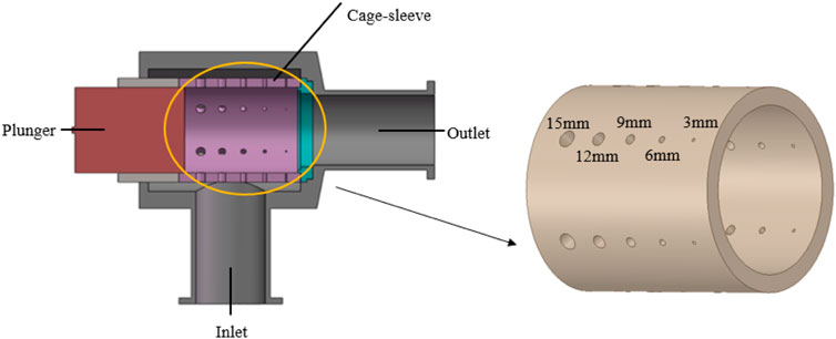
FIGURE 4. Diagram of the cage-sleeve throttling valve structure.
The throttling holes on the cage sleeve are not continuous, and the size of the holes is not the same. This study uses the method of the specific area defining the opening degree, which is the ratio of the open hole area to the total area of the cage-sleeve hole (Feng et al., 2017). The opening degree is calculated as shown in :
According to Eq. 4 and 5 for single-hole calculation and simulation results, the flow rate of the throttling valve in this study has exceeded 200×104 sm3/d, which already meets the production requirements, when the 9, 6, and 3 mm throttling holes are all opened. On this basis, five groups of production opening degrees were determined. Since the gas flow capacity of different sized holes is not consistent, the number of holes determining the opening degree does not increase uniformly. In order to set an appropriate opening degree gradient, the final number of opened throttling holes is determined, as shown in Table 1:

TABLE 1. The number of opened throttling holes with their different opening degrees.
According to each different opening degree, we establish different geometric models, and then grid the model, specifically in the vicinity of the throttling holes for local grid refinement. This study used tetrahedrons mesh which was suitable for unstructured models. The element size is 5–10 mm, and the face size of the hole is 0.5–1.0 mm. The number of mesh is from 1 million to 3 million, and mesh meets the requirement of skewness, minimum orthogonal quality, and maximum aspect ratio, which ensure the accuracy and efficiency of computations in simulation software. The fluid of numerical computation is pure methane, following the SRK equation of real gas state equation, and the Realizable K-ε turbulence model and energy equation were adopted. The throttling inlet pressure is 20 MPa, and the inlet temperature is set at 330 K. As for the temperature of the wall, 280 K is set in our study, which is the temperature at the seabed. The second-order upwind scheme is used for discrete schemes, and the steady-state model is used for computation (Li et al., 2018).
Detailed Characterization of Physical Field of Subsea Throttling Valve Affected by Different Factors
By using numerical simulation software ANASY Fluent, the temperature, pressure, and velocity fields of high-pressure gas flowing through the orifice of the subsea throttling valve can be accurately characterized. According to the different backpressure of subsea pipeline and the opening degree of subsea throttling valve, the influence of the Joule-Thomson effect on the safety of gas flow under different factors is analyzed, then the local high-risk area of subsea throttling valve is found out. Finally, the safe and feasible operation suggestions of subsea throttling valve are put forward.
Appropriate Downstream Pipe Prefilling Pressure
As gas reaches the subsea wellhead, the pressure in the wellbore slightly decreases, so the subsea wellhead pressure is usually high during the early production stage. Subsea production piping to the central processing platform is usually prefilled with nitrogen to reduce the pressure difference between the upstream and downstream of the subsea throttling valves, reducing the temperature plunge caused by the throttling effect.
Prefilling pressure is a factor that needs to be considered in the field, and appropriate prefilling pressure is selected to meet the requirements of efficient and safe production. Unilaterally reducing the throttling pressure difference at both ends of the choke will consume a large amount of nitrogen, which will have certain requirements on the capacity of the prefilling pump and increase the cost. However, low prefilling pressure leads to low temperatures and hydrate formation risk after throttling. In order to determine the appropriate prefilling pressure, this paper simulates the subsea cage-sleeve throttling valve with a downstream prefilling pressure of 3–14 MPa and obtains the corresponding physical field parameters.
Firstly, the throttling valve is analyzed as a whole. It can be concluded from Figure 5 that the temperature of the gas will decrease to varying degrees after passing through the subsea cage-sleeve throttling valve. When the prefilling pressure is 4 MPa, the downstream temperature has been as low as −20°C, and the local low temperature at the outlet of the valve hole on the cage is as low as −90°C. When the downstream prefilling pressure is 8 MPa, the downstream temperature is slightly above 0°C, but there was still low temperature locally at the holes.
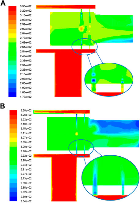
FIGURE 5. Vertical profiles of choke temperature under prefilling pressure of 4 MPa (A) and 8 MPa (B).
As for the local temperature change of the throttling holes, the overall trend is shown in Figure 6, which will first drop sharply at the valve hole and then rise up downstream. The same goes for pressure (Yu et al., 2017).
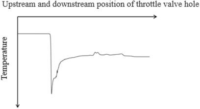
FIGURE 6. Temperature trend curve of the throttling valve hole.
The lowest temperature of the holes under different prefilling pressures is shown in Figure 7. The lowest temperature at the throttling holes can be as low as −100°C. For subsea X-trees, jumper bent pipelines and subsea gas transmission pipelines, the steel of low temperature resistant is required to be used once the temperature falls below −40°C, which will increase operating costs (Wang et al., 2013). Therefore, in the selection of prefilling pressure, the downstream needs to be filled at least 7 MPa to meet the requirements.
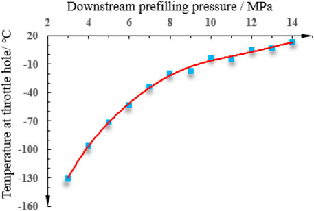
FIGURE 7. Temperature curve of throttling at different prefilling pressures.
At the same time, the speed in the cage hole is the largest in the whole throttling valve. One advantage of the cage-sleeve throttling valve is that the holes are distributed relative to each other along the cage, which dissipates the kinetic energy of the gas and reduces the vibration of the throttling valve. As can be seen from Figure 8, a violent vortex will be formed at the left plunger of the throttling valve, and a gas jet section will be formed along the outlet section at the right.
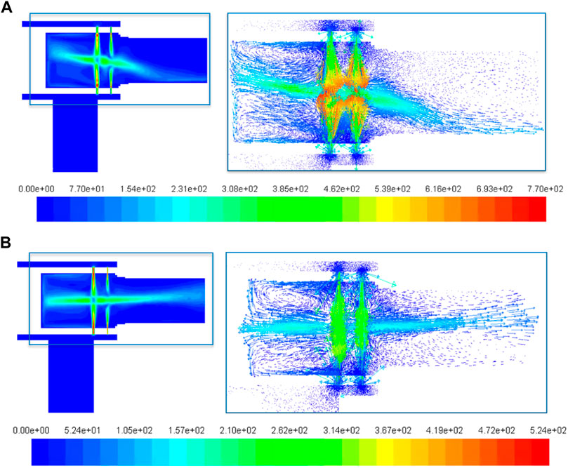
FIGURE 8. The vertical profile and vector diagram of throttling valve velocity under the prefilling pressure of 3 MPa (A) and 7 MPa (B).
Under different prefilling pressure, the maximum speed in the cage holes is shown in Figure 9. At the lower prefilling pressure, the gas velocity is over the local speed of sound. In the critical flow state, the large gas flow rate will cause serious cage-sleeve erosion, so choosing a throttling valve material needs to consider the maximum capability of erosion resistance (Nøkleberg and Søntvedt, 1998). If the gas carries sand, it will cause more serious abrasion damage (Zhu et al., 2021).
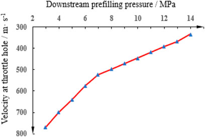
FIGURE 9. Peak velocity curve at valve hole under different prefilling pressures.
Throttling Valve Opening Degree to Match Production
As a component connecting the subsea wellhead and downstream gas pipeline, the main function of the subsea throttling valve is to match the appropriate production under different valve opening degrees. By simulating five groups of throttling valves with different opening degrees, the physical field parameters with corresponding opening degrees are obtained.
For production, the greater the valve opening degree, the greater the volume of gas through the same upstream and downstream pressure conditions. As shown in Figure 10, as the pressure difference between upstream and downstream increases, the pressure ratio between downstream and upstream gradually decreases from one, and the gas production gradually increases. When the critical pressure difference is reached, the gas production will no longer increase, and the gas will be in a critical flow state. Especially when the smaller opening degree, the control ability, and the flow capability of the valve are relatively weak. Once the gas production rapidly rises, it will be easy to reach the critical flow state. When the pressure difference continues to increase, the flow rate of gas does not change.
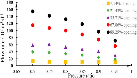
FIGURE 10. Diagram of flow rate and upstream and downstream pressure ratio through the throttling valve in different opening degrees.
There are two approaches to regulating production. One is to keep the pressure difference unchanged, then only change the valve opening degree; The other is to keep the opening degree constant and change downstream pressure. In the field, the easier parameter to confirm is the upstream and downstream pressure difference, so we usually choose to adjust the opening degree of the valve to adjust the gas production. In offshore gas development, we expect a high production. There are corresponding risks if the throttling valve opening degree is not adjusted properly. For example, under a certain flow rate, if the throttling valve is selected with a small opening degree, the downhole pressure needs to be reduced more to ensure the stability of production, and the throttling effect will be intensified. Therefore, the valve opening degree needs to match the flow capacity of the gas. At the same time, the impact of low temperature caused by the throttling effect should be reduced.
The velocity distribution at the throttling holes in the cage is related to the production. It can be seen from Figure 11 that the maximum velocity of gas passing through the holes is limited by the production at a small opening degree. As the opening degree increases, the velocity at the throttling holes decreases at the same flow rate. Under the condition of a large opening degree, the large and small holes in the cage are opened at the same time, and the maximum speed at the holes will increase gradually. This is consistent with the cognition that the larger the opening degree, the stronger the gas flow capacity (Zhang and Zhao, 2021).
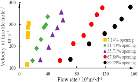
FIGURE 11. Diagram of flow rate and throttling holes speed through the throttling valve in different opening degrees.
After the gas flows through the throttling valve holes, the downhole velocity gradually tends to be stable as the pipe diameter increases. However, the downstream pressure is lower than the upstream pressure, so the velocity of gas downstream is increased compared with the upstream velocity, so the shear stress of gas on the downstream pipe wall increases accordingly (Li et al., 2021). Figure 12 shows the inlet and outlet velocity of the throttling valve under different pressure ratios at the opening degree of 89.29%. It shows that the downstream velocity is slightly higher than the upstream flow rate when the upstream and downstream pipe diameters are the same. In the design of the downstream pipeline, it is necessary to consider the stability of film formation in the pipeline after corrosion inhibitor injection. If the corrosion inhibitor film is more stable, the downstream gas velocity can be greater. Therefore, the gas velocity after throttling should be considered when analyzing the maximum design gas velocity of the subsea pipeline. In the case of fixed corrosion inhibitor film stability, the downstream velocity can not exceed the safety design value by reducing the throttling pressure difference or increasing the downstream pipe diameter.
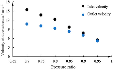
FIGURE 12. Comparison diagram of inlet and outlet velocity under different pressure ratios at an opening degree of 89.29%.
Risk Analysis at Subsea Throttling Valve
Through the temperature field simulation of the throttling valve, it is found that when the backpressure in the pipeline is 7 MPa, the downstream temperature is around 0°C. If no corresponding solutions are taken, the risk of hydrate formation will be extremely high under a low-temperature and high-pressure condition (Fu et al., 2020). At present, the common solution of hydrate prevention is to change the thermodynamic formation conditions of hydrate and inject a large amount of methanol and ethylene glycol before the producing wing valve (Wang et al., 2018).
The temperature of hydrate formation can be increased by injecting different weights of hydrate inhibitor. Figure 13 is the phase equilibrium curve of hydrate formation obtained through simulation under different thermodynamic conditions. As can be seen from the figure, the different hydrate inhibitors with the same mass fraction have slightly different inhibition effects. Under the condition of high temperature and pressure, the injection effect of ethylene glycol is better than that of methanol. Therefore, it is recommended to inject ethylene glycol before going through the subsea throttling valve, then methanol after going through the cooling and depressurization of the throttling valve.
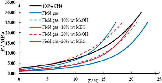
FIGURE 13. Phase equilibrium curves of hydrate formation in different conditions.
In the stable stage of production, the temperature upstream of the subsea throttling valve can reach 70°C and the pressure is up to 30 MPa. Even if the temperature and pressure drop rapidly after the gas passes through the throttling valve, the risk of hydrate formation is low. However, in the shut-in stage, due to the lack of an upstream gas heat source and the influence of the low temperature of the seabed, once the well starts up, the risk of hydrate formation will be very high under the superposition of the throttling effect at the subsea throttling valve. It is necessary to accurately characterize the temperature and pressure field at the subsea throttling valve and put forward the corresponding hydrate inhibitor injection scheme (Guan et al., 2014).
Low temperature will not only have the risk of hydrate formation but also affect the strength of the manifold. Subsea pipeline has requirements on temperature resistance range, and API has made relevant standards on temperature rating of materials related to subsea X-tree, as shown in Table 2 (Jiang et al., 2018). It shows that pipelines with different temperature levels meet different production conditions. For high temperature and high-pressure gas wells, once there is a serious throttling effect, the gas temperature changes sharply, and the material of pipelines and valves have to adapt to large temperature changes. Therefore, in the early design and valve selection, it is necessary to accurately consider the throttling valve temperature change.
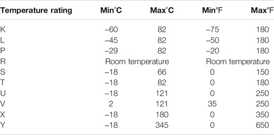
TABLE 2. API temperature rating table.
Conclusion and Recommendation
The structure of subsea X-trees is complex, and there are many valves. The size of the flow channel at the holes of the subsea throttling valve changes significantly, and the throttling effect is significant, so the temperature and pressure drop is large. It is necessary to take the fine characterization of physical field and risk analysis of subsea cage-sleeve throttling valve, so the following conclusions are drawn:
1) Determining the appropriate prefilling pressure in the downstream pipeline is conducive to the safe production of the subsea throttling valve. Based on the characteristics of the cage-sleeve throttling valve and the Joule-Thomson effect, it is recommended to prefill the downstream of the throttling valve at a pressure of about 7 MPa for the simulated deepwater well case. This can not only reduce the throttling effect, avoid extreme low temperature, and reduce the risk of hydrate formation, but also reduce the risk of valve hole erosion.
2) Select the throttling valve opening degree to match the production. The throttling valve controls the fluid flow and ensures regular production. Before the selection and design of the throttling valve, it is necessary to understand the flow characteristics of the throttling valve and match the appropriate opening degree considering the downstream pressure and expected production.
3) The temperature field and velocity field at the subsea throttling valve can be accurately described by the simulation of the 3D model, which is helpful to analyze the risk of hydrate formation under different conditions, select appropriate throttling valve materials and ensure the smooth subsea production.
These physical fields are based on the cage-sleeve throttling valve model that we built, and the physical field varies slightly from model to model. Meanwhile, this study is based on the steady-state model, and future researchers can study the transient model to more accurately describe the physical field dynamic process of the subsea throttling valve.
Data Availability Statement
The raw data supporting the conclusion of this article will be made available by the author, without undue reservation.
Author Contributions
DJ, WM, YH, and YY contributed to the conception and design of the study. ZJ organized the database. YZ performed the statistical analysis. YG wrote the first draft of the manuscript. YZ and ZJ wrote sections of the manuscript. All authors contributed to manuscript revision, read, and approved the submitted version.
Conflict of Interest
Author DJ, WM, YH, and YY were employed by the company CNOOC.
The remaining authors declare that the research was conducted in the absence of any commercial or financial relationships that could be construed as a potential conflict of interest.
Publisher’s Note
All claims expressed in this article are solely those of the authors and do not necessarily represent those of their affiliated organizations, or those of the publisher, the editors and the reviewers. Any product that may be evaluated in this article, or claim that may be made by its manufacturer, is not guaranteed or endorsed by the publisher.
Acknowledgments
The authors gratefully acknowledge the financial support provided by the Science and Technology Major Program of CNOOC Ltd. (No. CNOOC-KJ135ZDXM38ZJ05ZJ) and the National Natural Science Foundation of China (No. 51876222).
References
Feng, S., Zhang, J., Wang, P., Jin, Z., and Li, Y. (2017). Study on Valve Core Size and Opening Degree of Sleeve Choke Used in Gas Production. Oil Field Equipment 46 (1), 48–53. doi:10.3969/j.issn.1001-3482.2017.01.012
Fu, W., Wang, Z., Zhang, J., Cao, Y., and Sun, B. (2020). Investigation of Rheological Properties of Methane Hydrate Slurry with Carboxmethylcellulose. J. Pet. Sci. Eng. 184, 106504. doi:10.1016/j.petrol.2019.106504
Gharaibah, E., and Zhang, Y. “Flow Assurance Aspects and Optimization of Subsea Choke Valve - Sand Management and Erosion,” in Proceedings of the OTC Brasil, Rio de Janeiro, Brazil, October 2015. doi:10.4043/26250-MS
Grace, A., and Frawley, P. (2011). Experimental Parametric Equation for the Prediction of Valve Coefficient (Cv) for Choke Valve Trims. Int. J. Press. Vessels Piping 88 (2), 109–118. doi:10.1016/j.ijpvp.2010.11.002
Guan, L., Ren, J., Sun, B., and Gao, Y. (2014). An Optimization of Hydrate Inhibitor and its Injection Method for the Testing of Deep Water Gas Wells. China Offshore Oil and Gas 26 (2), 55–60.
Hong, C., Estefen, S. F., Wang, Y., and Lourenço, M. I. (2018). An Integrated Optimization Model for the Layout Design of a Subsea Production System. Appl. Ocean Res. 77, 1–13. doi:10.1016/j.apor.2018.05.009
Jiang, D., Li, Z., Qin, H., Wang, E., Xu, F., and Wang, Y. (2018). Type Selection and Function Design of Subsea Christmas Tree in Lingshui 17-2 Gas Field. China Pet. Machinery 46 (7), 31–38. doi:10.16082/j.cnki.issn.1001-4578.2018.07.007
Ju, P., Li, D., Jing, Y., Wang, W., and Zhang, H. (2021). Low Temperature Analysis during Initial Start-Up of Deepwater Christmas Tree. J. Salt Sci. Chem. Industry 50 (05), 50–52. doi:10.16570/j.cnki.issn1673-6850.2021.05.015
Li, Q., Sun, Q., Cheng, B., Liu, G., Yao, H., Wang, J., et al. (2021). Key Technologies for Engineering Design of Deepwater Subsea Production System in LS17-2 Gas Field. China Offshore Oil and Gas 33 (3), 180–188. doi:10.11935/j.issn.1673-1506.2021.03.021
Li, Z., and An, W. (2020). Progress and Outlook of Equipment Engineering Technologies for Subsea Oil and Gas Production System in China. China Offshore Oil and Gas 32 (02), 134–141. doi:10.11935/j.issn.1673-1506.2020.02.016
Li, Z., Luo, X., Chen, J., Ma, Q., and Kong, X. (2018). Numerical Simulation and Hydrate Formation Analysis of Sleeve Choke. J. Chengde Pet. Coll. 20 (3), 43–46+73. CNKI:SUN:CDSY.0.2018-03-013.
Malavasi, S., and Messa, G. V. “CFD Modelling of a Choke Valve under Critical Working Conditions,” in Proceedings of the ASME 2014 Pressure Vessels and Piping Conference, Anaheim, California, July 2014. doi:10.1115/pvp2014-28629
Nøkleberg, L., and Søntvedt, T. (1998). Erosion of Oil & Gas Industry Choke Valves Using Computational Fluid Dynamics and Experiment. Int. J. Heat Fluid Flow 19 (6), 636–643. doi:10.1016/S0142-727X(98)10039-5
Rassenfoss, S. (2011). Growing Offshore Water Production Pushes Search for Subsea Solutions. J. Pet. Tech. 63 (8), 36–40. doi:10.2118/0811-0036-JPT
Shoghl, S. N., Naderifar, A., Farhadi, F., and Pazuki, G. (2020). Prediction of Joule-Thomson Coefficient and Inversion Curve for Natural Gas and its Components Using CFD Modeling. J. Nat. Gas Sci. Eng. 83, 103570. doi:10.1016/j.jngse.2020.103570
Sotoodeh, K. (2019). A Review on Subsea Process and Valve Technology. Mar. Syst. Ocean Technol. 14 (4), 210–219. doi:10.1007/s40868-019-00061-4
Wang, J., Zhou, X., Chen, H., and Chen, J. (2013). Simulation and Analysis on Cold Temperature Propagation in Downstream of Subsea Production Choke under Momentary Flowing during Gas Well Startup: Case Study of Panyu Deep Water Gas Field. China Offshore Oil and Gas 25 (6), 105–108. CNKI:SUN:ZHSD.0.2013-06-020.
Wang, Z., Zhao, Y., Zhang, J., Pan, S., Yu, J., and Sun, B. (2018). Flow Assurance during Deepwater Gas Well Testing: Hydrate Blockage Prediction and Prevention. J. Pet. Sci. Eng. 163, 211–216. doi:10.1016/j.petrol.2017.12.093
Yu, P., Liu, Z., Wu, X., Kong, R., Wang, W., Li, T., et al. (2017). Optimization Design and Application of Subsea Surface Chokes. Oil Field Equipment 46 (4), 61–65. doi:10.3969/j.issn.1001-3482.2017.04.015
Zhang, B., and Zhao, J. (2021). Research on the Influence of Throttle Valve Cage Sleeve Structure on Throttling Effect. Appl. Eng. 5 (1), 16–21. doi:10.11648/j.ae.20210501.13
Zhang, J., Wu, Z., Huang, L., Lu, P., Wang, J., and Li, Y. (2010). Method Study on Anomalous Pressure Gas Wellhead Choke Valve Turndown Ratio Control. Oil Drilling Prod. Tech. 32 (S1), 115–117. doi:10.3969/j.issn.1000-7393.2010.z1.031
Zhao, X., Wang, D., Liu, W., Ren, G., and Jin, L. (2014). Flow Numerical Simulation for Production Channel in Subsea X 'mas Tree Based on CFD. China Pet. Machinery 42 (11), 105–108. doi:10.3969/j.issn.1001-4578.2014.11.025
Zheng, J., Yan, X., and Dou, Y. (2020). Research on Failure Characteristics of Natural Gas Downhole Throttle. J. Fail. Anal. Preven. 20 (4), 1155–1161. doi:10.1007/s11668-020-00919-5
Keywords: cage-sleeve throttling valve, subsea prefilling pressure, opening degree, hydrate prevention, flow assurance
Citation: Jiang D, Meng W, Huang Y, Yu Y, Zhou Y, Jiang Z and Gao Y (2021) Characterization of Physical Field and Flow Assurance Risk Analysis of Subsea Cage-Sleeve Throttling Valve. Front. Earth Sci. 9:786996. doi: 10.3389/feart.2021.786996
Received: 30 September 2021; Accepted: 01 November 2021;
Published: 30 November 2021.
Edited by:
Weiqi Fu, China University of Mining and Technology, ChinaReviewed by:
Haiwen Zhu, University of Tulsa, United StatesMingzheng Yang, Louisiana State University, United States
Copyright © 2021 Jiang, Meng, Huang, Yu, Zhou, Jiang and Gao. This is an open-access article distributed under the terms of the Creative Commons Attribution License (CC BY). The use, distribution or reproduction in other forums is permitted, provided the original author(s) and the copyright owner(s) are credited and that the original publication in this journal is cited, in accordance with accepted academic practice. No use, distribution or reproduction is permitted which does not comply with these terms.
*Correspondence: Yonghai Gao, upcgaoyh@126.com