A comprehensive review on EV power converter topologies charger types infrastructure and communication techniques
 Pradeep Vishnuram1
  Narayanamoorthi R1
  Suresh P1
  Vijayakumar K1
  Mohit Bajaj2,3,4*
  Tahir Khurshaid5*
  Ali Nauman6*
  Salah Kamel7
- 1Department of Electrical and Electronics Engineering, Electrical Vehicle Charging Research Centre, SRM Institute of Science and Technology, Chennai, Tamil Nadu
- 2Department of Electrical Engineering, Graphic Era (Deemed to be University), Dehradun, India
- 3Graphic Era Hill University, Dehradun, India
- 4Applied Science Research Center, Applied Science Private University, Amman, Jordan
- 5Department of Electrical Engineering, Yeungnam University, Gyeongsan, Republic of korea
- 6Department of Information and Communication Engineering Yeungnam University, Republic of korea
- 7Electrical Engineering Department, Faculty of Engineering, Aswan University, Aswan, Egypt
The energy transition is a crucial effort from many sectors and levels to create a more integrated, carbon-neutral society. More than 20% of all greenhouse gas emissions are attributed to the transportation sector, predominantly concentrated in metropolitan areas. As a result, various technological hurdles are encountered and overcome. It facilitates the adoption of electric vehicles (EVs) run on renewable energy, making them a practical option in the fight against climate change and the completion of the energy revolution. Recent developments suggest that EVs will replace internal combustion engine (ICE) during the next few months. The EV either gets all of its power from batteries and ultra capacitors or some of it from both. In a plug-in electric vehicle, the battery or ultra-capacitor is charged by an AC supply connected to a grid line. In a hybrid electric vehicle, the ICE charges the battery or ultra-capacitor. Regenerative braking is another way to charge the battery from the traction motor. In a plug-in electric vehicle, the energy from of the battery or ultra-capacitor is put back into the AC grid line. Electronic converters are essential to converting power from the grid line to the traction motor and back again. This paper examines the current state of the electric vehicle market throughout the world and its potential future developments. Power electronics converters (PEC) and energy storage devices significantly impact electric vehicles’ efficiency. Furthermore, general opinions about EVs are soon in this sector, as well as research topics that are still open to industry and University researchers.
1 Introduction
Recently, there has been significant growth in the number of initiatives aimed at increasing, establishing, and managing RES. Polluting, degrading, and adding to the greenhouse effect are all side effects of using conventional energy sources. Conventional vehicle significantly contributes to the transportation sector’s air pollution and greenhouse gas emissions. Carbon dioxide (CO2), sulphur dioxide (SO2), and nitrogen oxide (NO2) are released when gasoline, coal, or natural gas are burned in these automobiles, making them hazardous combustion vehicles. An internal combustion engine (ICE) loss is caused by friction and heat loss in the transferring section (Sharma and Sharma, 2019).
The replacement of ICE highlights the importance of EVs as the most incredible alternative for lowering emissions (Gryparis et al., 2020). Heavy-duty vehicle (HDV) energy efficiency is crucial due to its link to other policy instruments. Hence, this is critical because some HDVs, such as city buses and refuse trucks, are purchased in significant quantities by government organizations. Despite this, no technical comparison of the CO2 emissions or fuel consumption of vehicles in the same class. Battery-powered EV propulsion demands a massive battery pack with a restricted range (Fontaras et al., 2016). Power electronic converters of various types are connected to energy storage systems (ESSs) in electric vehicles in various ways (Khalid et al., 2019). An EV’s energy storage and control optimization are detailed (Islam and Pota, 2013).
Power management control (PMC) based on a fuzzy inference system has improved due to genetic algorithm (GA) assistance. To decrease the total size of the hybrid energy storage system and increase the EV range, the GA is used offline to optimise the lower and upper membership limitations. An accurate model for estimating the energy needs of EVs was created by Miri et al. Since the amount of power required to operate a vehicle’s accessories varies widely, this estimation is included in the EV’s design. Energy storage systems (ESSs) are charged by connecting them to an AC power source, such as the utility grid or a dedicated charging station (Wu et al., 2017). DC-DC converters are necessary to regulate the power flow in the EV (Elsayad et al., 2020).
An energy-harvesting and power-demanding bidirectional non-isolated DC-DC converter is designed (Navarro et al., 2020). It is challenging since it depends on the load characteristics, source voltage, and duty cycle (Fardahar and Sabahi, 2020). Kanamarlapudi et al. developed a novel full-bridge isolated DC-DC converter with a passive auxiliary circuit that offers zero voltage switching (ZVS) for every significant switch across the battery charging range (Kanamarlapudi et al., 2018). The creation of diverse energy sources reduces vehicle running costs and enhances efficiency. The hybrid electric vehicle (HEV) has developed as an effective alternative for minimizing greenhouse emissions due to transport. Compared to ICE vehicles, HEVs claim superior fuel economy by maintaining the state of charge (SOC) (Kumar and Jain, 2014). By using renewable energy to power EVs, green charging systems (GCSs) with lower CO2 emissions and promote the use of RES in the energy sector (Najafi et al., 2021a).
Grid is the primary source for charging EVs, but in practice, they also use renewable energy sources and coal for their energy needs (Mamun et al., 2022). The main problems with HEVs seem to be the fuel tank and regenerative braking. Plug-in hybrid electric vehicles (PHEVs) with externally charged batteries can solve the above-said problem (Shakeri et al., 2018). The most recent technology has developed a carbon-free EV charging station utilizing solar energy, drastically reducing pollutants and the effect of EVs on the electrical network. The expansion of renewable energy will significantly accelerate the use of maximum power converters with much more efficient and reliable conversion of boundless energies into an electricity network. PHEVs address the issue of restricted driving range by providing vehicle-to-grid (V2G) functionality (Islam and Cirrincione, 2016).
Multiple communication connection qualities are necessary to suit the demands of various charging mechanisms. A component powered by multiple wireless connections is necessary for a large-scale EV charging system with static, dynamic, and quasi-dynamic charging to enable effective interaction among numerous network elements (Yu et al., 2019). Consequently, to maintain their economic performance in the coming years, several firms are doing more thorough research into BEV charging options (Verma and Singh, 2019). The battery management system (BMS) is notable in light of the challenging-to-attain safety and dependability standards (Momete, 2018). The new distribution network, driven by EVs and energy markets, is expected to play a significant role in autonomous charging stations at a port, public parking lots, and quick charging infrastructure (Nunes et al., 2016). This article put forth a comprehensive review of EV technology, which includes selection of motors, battery requirements, power electronic converters, charging technologies, different charging methods, EV market and charging infra structure, with future directions. This article will help the kindle researchers who wish to work in EV technologies.
The course of the paper is organised as follows. The details of electric motors for EV applications are explained in Section 2, whereas in Section 3, the battery requirement for EVs is briefed. Power converters and charging communication technologies are elucidated in Sections 4, 5, respectively. Sections 6, 7 briefs about the conductive and inductive charging respectively. The electric vehicle market and Repercussions of electric vehicle charging infrastructure are briefed in Section 8, 9, respectively. The future direction of the research area is explained in Section 10, birds view. The conclusion of the paper is drafted in Section 10.
2 Electric motors for EV
An integral component of the EV is the electric motor, which includes power electronics and batteries. In EVs, where weight and space are constrained, more power and torque density enable improved driving characteristics in a small, straightforward design. The other factor, efficiency, is improved. Whenever the vehicle is in motion, the energy stored in the battery is wasted, resulting in a more excellent range despite the same storage space. According to multiple unique problems in motor design, the EV industry has applied a range of distinct options, comprising wound rotor, permanent magnet and induction. The rare metals used in permanent magnet motors are subject to price fluctuations, have a restricted geographical distribution system, and come with a unique mix of benefits and drawbacks in terms of development costs, dependability, and accessibility. DC motors offer a straightforward monitoring system compared to AC motors. Again, contrasted to DC motor drives, there are several significant benefits of using AC motors, such as increased efficiency through less motor frictional loss, fewer maintenance requirements, robustness, and maximum power density.
Motors preferred for EV applications are induction motor (IM), permanent magnet (PM), switched reluctance motor (SRM) and brushless DC motor (BLDC). Though challenging, evaluating various versions of these machines is non-etheless a task. IM has a simplified construction, requires minimal, is less costly, and has better overloading performance than PM-based motors (Hannan et al., 2018). On the other hand, PM motors outperform IM in terms of effectiveness and portability. Its tiny size, high power densities, and efficiency make it superior to IM (Barkas et al., 2020).
However, its torque decreases with increasing speed when subjected to a load. Therefore, it can only be used to a certain extent. As the torque changes, there is an audible noise produced. Compared to the other types of motors discussed, the permanent magnet synchronous motor (PMSM) stands out well. It operates across a wide range of speeds, is extremely powerful and efficient, causes no harmonic distortion, and is simple to operate (Sun et al., 2019a). However, the cost of PMSM-based drives exceeds that of both BLDC and IM-based systems. The switched reluctance motor (SRM) has several benefits over the IM and PMSM, including a magnet-free and sturdy rotor design that enables incredible velocities and is highly reliable by construction. Ripple torque reduction is among the most important and challenging SRM design elements to handle whenever it relates to vehicle applications. The SRMs for significantly higher torque in EV with reduced ripple torque, disturbance, and auditory concerns (Lan et al., 2021). The performance comparison of different motors used for EV applications is given in Table 1.
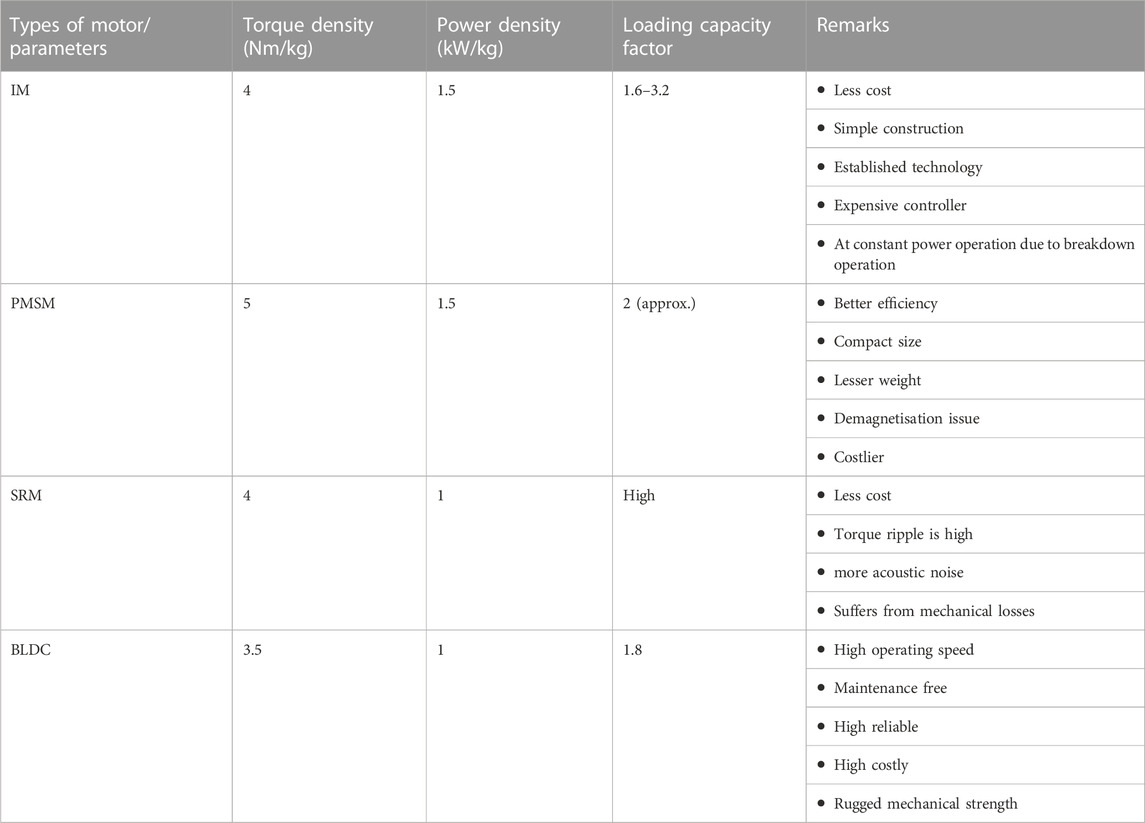
TABLE 1. Performance comparison of different motors.
3 Requirements of battery for EVs
Electric vehicles (EVs) charge their batteries, super capacitors, fuel cells, or internal combustion engine (ICE) to power internal electrical and electronic load functions (Chan and Chau, 1997; Amjadi and Williamson, 2010a; Naghizadeh and Williamson, 2013; OnarKobayashi and Khaligh, 2013; Cabezuelo et al., 2017). The automobile cannot be powered in fuel mode by the fuel cell’s electricity. Consequently, the unidirectional boost converter boosts it (Jafri and Gupta, 2016). Several electrical and technological loads are placed on the car, enhancing its opulent characteristics and convenience.
A power converter supplies energy to specific electrical loads requiring higher AC voltage, such as air conditioners and automatic headlights. A DC motor-fed mirror and driving seat adjustments receive electricity from a battery or fuel cell through a DC-DC converter, which requires various voltage levels. The projection lamp needs 42 V, and the internal lighting needs 12 V to operate. Low voltage is required to function electronics components such as sensors, telecommunication networks, and tachometers. As the electrical/electronic load on the car rises, separate voltage output feeds are required, which are not achievable with a unified battery. The effectiveness of a vehicle powered by a single charge decreases as the quantity of DC-DC converters grows with rising diverse rating loads. The combination automotive system uses two forms of design (AdamsKlobodu and Apio, 2018). The other is a solitary, ICE- or fuel-cell-powered vehicle system (36 V). A different type is an ICE, or fuel cell, that uses two batteries (14 V and 42 V).
Figure 1 illustrates the block diagram of the battery with the power converter. This scheme uses a dual battery to deliver power to low-voltage electrical equipment (Cabezuelo et al., 2017). 12 V and 36 V batteries are used for low and mid-voltage applications. Nevertheless, for the driving and high voltage applications, the 36 V from the battery is raised to 42 V. Overview of the EV system with the power electronic interface is illustrated in Figure 2. The voltage from the grid/generator charges the battery through the rectifier and DC-DC converter (Elnozahy and Salama, 2014), (Yong et al., 2015). The bidirectional DC-DC converter boosts the battery voltage and feeds to high-voltage DC loads. Then it is inverted using a three-phase inverter to get variable voltage and frequency supply for feeding to motors. Modern electric vehicles can recharge batteries using the energy lost during braking and de-acceleration. During that mode, the converter acts as a rectifier and the battery charges with the bidirectional converter (Amjadi and Williamson, 2010a), (Chung et al., 2000; Di Napoli et al., 2002; KhanAhmedHusain et al., 2015; Lulhe and Date, 2015; Choubey and Lopes, 2017).
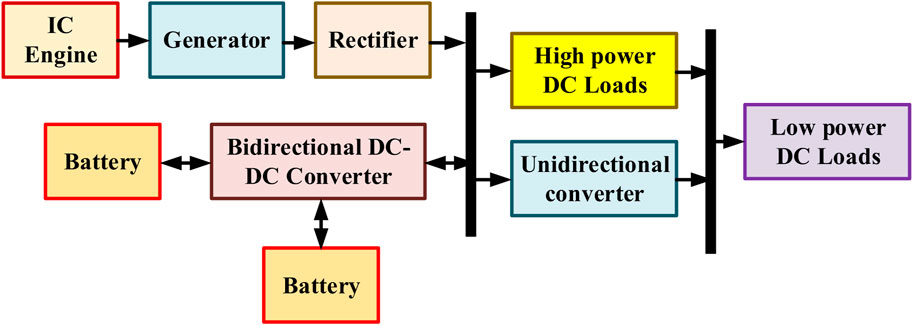
FIGURE 1. Block diagram of battery with the power converter.
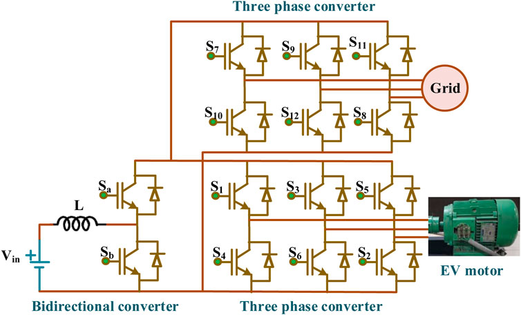
FIGURE 2. Overview of EV system with power electronic interface.
In the current EV system, the converter act as an inverter at the normal operating condition and a rectifier during the braking period. The controller fixes the operating mode upon the operation of the motor and produces the triggering pulses for the converter. The produced signal decides the operation of the converter, either in rectifier or inverter mode. The controller maintains the state of the charge (SOC) of the battery by monitoring it continuously. DC-DC converter regulates the output voltage by comparing the actual battery voltage with the reference voltage set by the user. Thus, the closed system maintains the battery voltage and speed of the motor.
4 Power converters for EV applications
The power converter plays a vital role in EV applications. As discussed in the previous section, Bi-directional DC-DC converters with boost and buck modes are preferred. In boost mode, the input voltage is boosted and fed to the motor, whereas the generated voltage from the motor during regenerative braking is bucked and fed to the battery. One of the well-known bidirectional DC-DC converter is illustrated in Figure 3, and the modes of operation are included in Table 2 (OnarKobayashi and Khaligh, 2013). The converter can operate in buck and boost modes upon selecting the proper switching pattern. Besides the basic topologies, several bi-directional converters are developed with single/multi-input, single/multistage and non-isolated multiphase converters.
FIGURE 3. Bidirectional DC-DC converter.
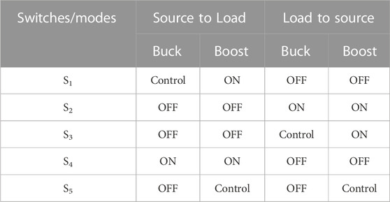
TABLE 2. Modes of the operation.
In (Amjadi and Williamson, 2010b), Authors have developed a novel single-input bi-directional buck-boost converter, as shown in Figure 4A. The developed topology can be operated in both buck and boost modes by selecting the proper switching pattern. The topology includes two controlled switches and three passive elements. In this topology, the output current ripple is high, which may damage the battery and discontinuous operation in boost mode results in the increased size of the filter capacitor. Emadi proposed a modified buck-boost converter with an anti-parallel diode as shown in Figure 4B (Emadi, 2005). The diode connected in parallel with the power switches decreases the voltage stress across the switches, increasing system efficiency. The circuit diagram of the H-bridge converter is shown in Figure 4C. They maintain the SOC as the desired value and charge the battery during the regenerative braking (Waffler and Kolar, 2009; WuLuShi and Xing, 2012; Choubey and Lopes, 2017; Bharathidasan et al., 2022). This topology results in more semiconductor switches. The circuit diagram of DC-DC CUK and SEPIC with Luo converter is illustrated in Figures 4D, E, respectively (Amjadi and Williamson, 2010a). The developed topology can buck and boost the output voltage, and a bidirectional current flow is also possible. The input and output current ripple is minimum. But the output current is discontinuous in the Luo converter, which requires a bulky output capacitor. Elements in non-isolated single-input converters are summarised in Table 3.
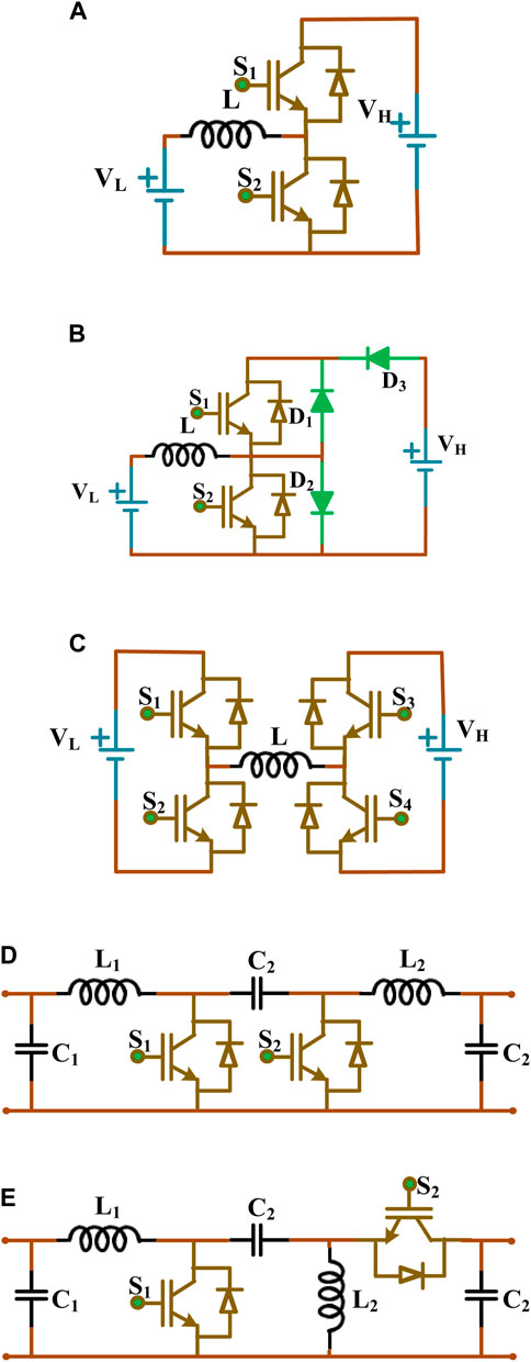
FIGURE 4. Non-isolated single input converters (A) buck-boost (B) modified buck-boost (C) H-bridge (D) CUK (E) SEPIC with Luo.
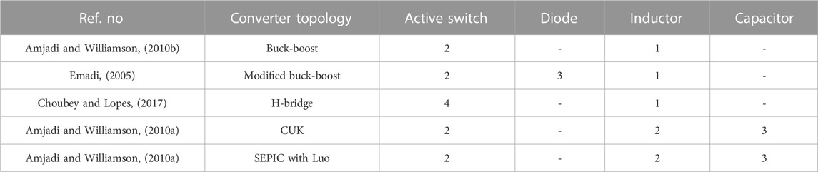
TABLE 3. Elements in non-isolated single-input converters.
The multiple-input fed bidirectional converter and single-input converters are developed for EV applications. The circuit diagram of the developed topology is illustrated in Figure 5. The input fed to the converter may be a battery, super capacitor or fuel cell in which battery-operated EV yield better response when compared with others (KhanAhmedHusain et al., 2015). A DC bus is maintained using a buck-boost converter with the battery and ultra-capacitor, as shown in Figure 5A. As two sources are used, voltage control is essential to maintain the value and to avoid circulating currents. A DC-DC converter with multiple sources is illustrated in Figure 5B (Khaligh, 2008). The converter can handle multiple different sources that possess different VI characteristics. Figure 5C illustrates the cascaded bidirectional converter for fuel cell-operated EVs. The converter can boost the input voltage with high gain (Marchesoni and Vacca, 2007). The prime disadvantage of this topology is that DC link voltage should be maintained more significant than the sum of source voltage to avoid circulating current. They possess higher efficiency if the sources are connected in the same direction. Figure 5D shows the circuit diagram of the multi-level power electronic converter (Di Napoli et al., 2002; Onwuchekwa and Kwasinski, 2011; Dusmez, 2012). The converters can operate buck and boost modes to maintain the DC bus voltage constant. Elements in non-isolated multiple-input converters are summarised in Table 4.
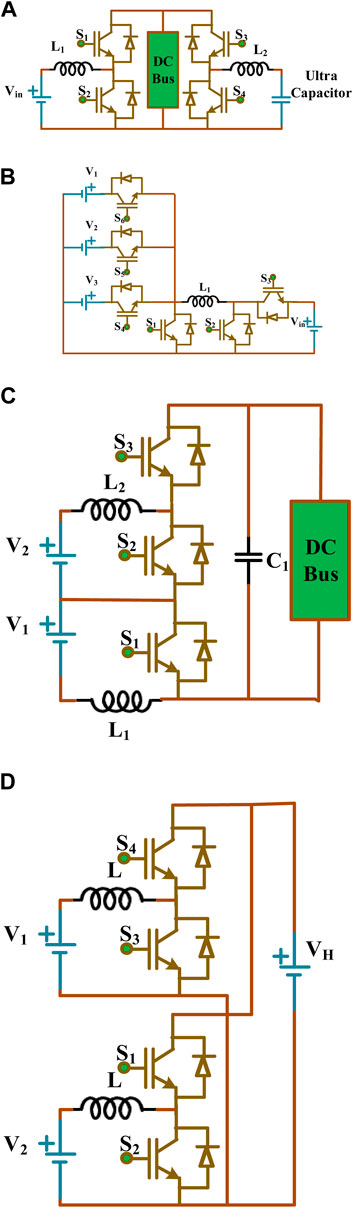
FIGURE 5. Non-isolated multi-input converters (A) buck-boost (B) DC-DC (C) cascaded (D) multi-level.
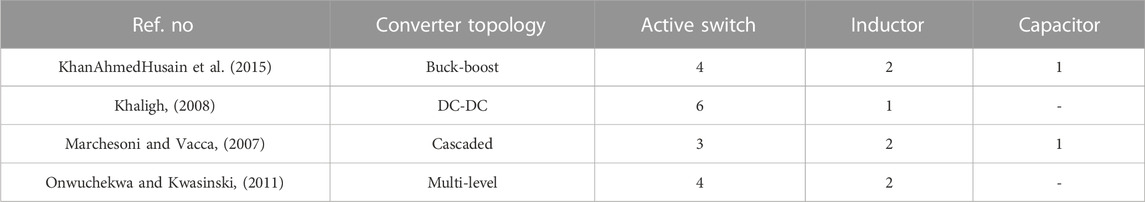
TABLE 4. Elements in non-isolated multiple-input converters.
Figure 6 depicts the non-isolated multiphase DC-DC converters used for electric vehicle applications. Figure 6A depicts the circuit diagram of interleaved boost three-phase converter (Khaligh and Li, 2010)- (YangGuanZhangJiang and Huang, 2018). The interleaved converter minimizes the input-output current ripples, significantly improving over the traditional bidirectional DC-DC converter. When there are multiple phases, the current ripple will decrease. Still ultimately, this will result in a fall in efficiency due to the increased number of passive and active elements required for each phase. Figure 6B illustrates the several structures in an interleaved converter (Ni et al., 2012). As the number of stages grows, the input/output filter gets smaller. This structure includes more active and passive elements than Figure 6A.
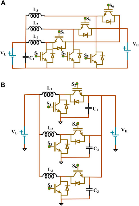
FIGURE 6. Non-isolated multiphase converters (A) interleaved boost (B) sixteen phase.
Figure 7 depicts electric vehicles’ various switched capacitor (SC) circuit configurations. Figure 7A depicts the circuit diagram of SC converter (Amjadi and Williamson, 2010a), (Ni et al., 2012), (Chung et al., 2000). The SC structure possesses the capabilities of buck, boost, and buck-boost power flow operation in either direction. The topology supports both mode A (buck operation) and mode B (boost operation) of operation. Mode-efficiency A’s of the illustrated topology is 85%, whereas mode-efficiency B’s is 80%. Figure 7B, C demonstrate quasi-resonant converter of single-level and two-level topologies (Lee and Chiu, 2005). By utilizing an SC structure and a single inductor, the topology helps to alleviate the issue of current stress. The converter can achieve soft switching with the assistance of L and C, which decreases the losses. As a result, the MOSFET semiconductor device being switched ON and OFF in a condition with zero current, the EMI issue is significantly mitigated. The efficacy of the topology is 93%. Higher voltage conversion ratios require more SC stages. Table 5 lists the summary of various converter topologies for EV applications.
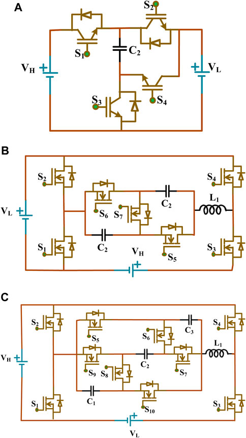
FIGURE 7. Switched capacitor converters (A) bidirectional (B) single-level quasi-resonant (C) two-level quasi-resonant.

TABLE 5. Summary of various converter topologies for EV applications.
5 Charging communication technologies
Dynamic wireless charging necessitates a distinct communication network with an exceptionally low delay and high dependability to enable effective connection with the fast charging arrangement through the car’s on-road capabilities (Abboud et al., 2016). The ability of the communications network is an essential factor that is determined by the amount of data that has to be sent and is reliant on this factor. Methods of good communication, whereby a network connection is built between the charging station and EV, are necessary to accomplish and control efficient synchronization of EVs on the internet of electric cars. It has been the impetus for developing 5G V2X innovation, which builds upon existing LTE, LTE-advanced (LTE-A), and LTE C-V2X networks. It also solves certification requirements such as super reliability, better portability, lower energy consumption, and more extensive density interconnections (Dai et al., 2018). Millimetre-wave (mmWave) technology is used to investigate the massive multiple-input multiple-output (MMIMO) technique (Busari et al., 2019). Several communication technologies, such as mmWave, D2D, MMIMO, and software-defined networks (SDN), are used for communications (Chen et al., 2017; Ahmed et al., 2019; Dagdougui et al., 2019; Zhang et al., 2020).
Static synchronization is concerned chiefly with task scheduling of driven automobiles at access points or in commercial parking areas (Zhang et al., 2020). Consequently, the vehicle’s manoeuvrability is disregarded. The coordination that takes mobility into account considers not only the packages that need to be delivered but also where they need to be sent, how far they need to go, and how much energy they need before they get charged (Wang et al., 2019). Assessed is the best battery charging plan that may be used for EBs within a BSS (You et al., 2016). Several approaches to charging synchronization and routing management have been discussed in the research that has been published. The most current developments in 802.11bd and NR V2X standards have been analyzed (Kosmanos et al., 2018), (Naik et al., 2019). The United States National Institute of Standards and Technology (NIST) created a cyber-security structure that offers businesses recommendations on avoiding, detecting, and preventing cybersecurity risks. Recent years have seen a rapid increase in the purchase of electric vehicles, even though the overall cost of owning an EV is more than owning an internal combustion engine version of the same vehicle type (Forocoches Electricos, 2017).
DSRC’s dependability quickly crumbles in highly congested systems due to severe network problems in inter-cluster communication (Framework Convention on Climate Change, 2015). Consequently, problems with quasi-dynamic charger synchronization develop, particularly in situations where electric vehicles benefit from high vehicle concentrations to increase their efficient charging duration and enhance the amount of electricity collected. Standards committee recommendation for IEEE 802.11bd, the problems of interference and non-line of sight (NLOS) functioning that plague DSRC based on IEEE 802.11p are addressed in the DSRC technique known as DSRC. To improve channel estimates with the rapidly changing channels seen in a moving vehicle, the latest revision of IEEE 802.11bd includes a new feature called midambles, which function similarly to opening paragraphs but are put amid the frame (Forocoches Electricos, 2017). In addition, unlike IEEE 802.11p, IEEE 802.11bd allows for many packet forwarding to ensure a steady connection. On the other hand, the physical layer delay also referred to as issues that limit inside the wireless medium, is shorter for IEEE 802.11bd than for IEEE 802.11p.
6 Conductive charging technologies
The electricity is transferred to an electric vehicle by conductive charging by a direct copper connection between the grid system and the EV. This charging technique is very reliable and has a high-efficiency level. There are two main types of conductive charging infrastructure: on-boarding and off-boarding. Slow charging is often performed using onboard charging infrastructures, wherein the charger facilities and battery storage system are housed within the electric vehicle’s chassis. On the other hand, off-board charging infrastructures are made to charge electric cars quickly. Parking garages, shopping malls, hospitals, universities, and interstates are familiar places to find off-board charging infrastructures. Electrified automobiles use a conductive charging method, such as the Tesla Roadster, Nissan Leaf, and Chevrolet Volt. Figure 8 displays on-board and off-board charging facilities. The Society of Automatic Engineers (SAE) has established various charging levels for electric vehicles, outlined in Table 6.
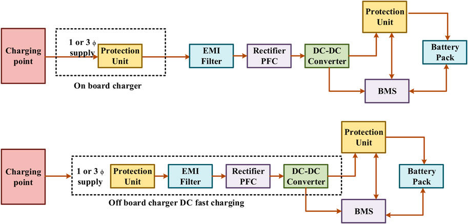
FIGURE 8. On-board and off-board charging facilities.
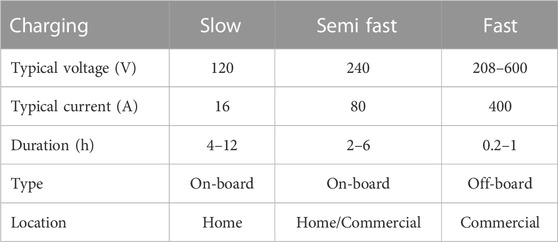
TABLE 6. Various charging levels for electric vehicles.
As previously established, power quality measurements for EV chargers are crucial. One such indication is the total harmonic distortion (THD), which quantifies the amount of harmonic distortion delivered into the AC input by the charger (PF). For recharging electric vehicles, (Bai and Lukic, 2013), presents a 12-pulse rectifier and two buck-boost converters. To lessen the input current’s harmonics, the virtual impedance injection technique is explained. Improved input power factor and 3.34 percent total harmonic distortion of the input line current are the results of this modification. The authors propose (Rivera et al., 2015; Rivera and Wu, 2017) that a bipolar dc structure be formed at the output of a grid-tied neutral point-clamped converter in order to charge electric vehicles. Because of its bidirectional energy conversion capabilities, it is well suited for use in linking electric vehicle power to the utility grid. Under balanced load conditions, the THD was found to be 5.8 percent, whereas under unbalanced load conditions, it was found to be 7.3 percent.
The development of the two-stage, bidirectional dc rapid charging facilities in MATLAB/Simulink (Arancibia and Strunz, 2012; Reed et al., 2012; Gjelaj et al., 2017). On the other hand, the efficacy of the chargers in addressing the problems with the power quality is not present. The two-stage energy conversion procedure is proposed to facilitate the integration of a flywheel energy storage system with a charging system for electric vehicles (Sun et al., 2016). On the other hand, none of the power-quality concerns raised by the suggested charging scheme is addressed. Several distinct designs for EV chargers are explored, each involving low-frequency or high-frequency (LF or HF) transformers for electrical isolation (Aggeler et al., 2010). For charging electric vehicles during peak demand on the electric grid, a two-stage, bidirectional charging structure is considered together with a dynamic load control approach (Ahmadi et al., 2015).
For electric vehicle charging stations, Bai. et al. have proposed ac-to-dc converters with 6, 12, or 18 pulses and the difficulty of constructing the necessary specialized transformers to get that many pulses (Bai et al., 2010). The THD in the input line current for a 12-pulse converter is 11.5%. A dc-active power filter (dc-APF) circuit is developed using a 12-pulse rectifier for recharging electric vehicles (Bai and Lukic, 2011). When looking at the power quality of the input line current, the stated findings were highly promising. However, a significant heating issue is introduced by high-frequency switching in dc-APF to transform the input current into a sinusoidal waveform. In (Joy et al., 2013), it is detailed how a two-step, two-way charging setup for electric vehicles may work. High-frequency switching is a part of this design. However, it doesn’t appear appropriate for a charging setup for electric vehicles that requires a lot of energy (in the MW range).
A bidirectional, multilayer cascaded converter with a medium switching frequency of 2880 Hz is proposed (Crosier et al., 2012) for use in EV charging stations. The authors propose a two-stage charging process for EVs. Because the dc/dc converter provides isolation in this charger, the isolation transformer may be smaller (Vasiladiotis et al., 2012), (Prakash et al., 2022). The switching frequency of this design is 10 kHz, and the circuit uses thirteen DC-DC converters linked in parallel. It is proposed to build a high-power bidirectional EV charger using a matrix converter and two inverters (Waltrich et al., 2012). On the other hand, this design uses many power electronics switches operating at high frequencies.
Slow charging uses a typical 120 V AC single-phase outlet with a 15 A–20 A current capability. One end of a typical electric socket is NEMA5-15R/20R, while the other is a standard SAEJ1772 connection. This level’s power consumption ranges between 1.4 and 1.9 kW, depending on the current drawn from the grid. Typically, it takes 8–16 h to charge the battery altogether (Introduction, 2014). The price range for facilities at this degree of charge ranges from $500 to $880 (Morrow, 2008).
The semi-fast charging technique is typically implemented in private and public institutions, including hospitals, universities, and retail malls. Private equipment utilizes 1 ϕ 230 VAC plug with a 40 A current size, whereas public facilities utilize a three-phase 400 VAC output having an 80 A existing size (Bai and Lukic, 2013). This charging level uses SAEJ1772 (Plug-in electric vehicle, 2013). This charge level has a power rating of 7.7–25.6 kW, and it typically takes 4–8 h to fully charge the battery of an electric vehicle (Introduction, 2014). Costs associated with semi-charging construction are significant, anywhere between $2150 and $2300 on average (Morrow, 2008).
Public and private charging stations alike must adhere to the rapid charging requirement. This charging protocol mimics ICE fueling stations that use fossil fuels. The longest time an EV may spend charging at this rate is 10–15 min, at which point it will have been charged to 80% of its theoretical capacity. Only up to 80% of the entire capacity of an EV battery is considered to be charged using this approach (Braunl, 2012). Charging the remaining 20% needs charging at constant voltage, which takes time. A three-phase power supply between 208 V and 600 V alternating current and a maximum current capacity of 200 A is required for this level of charging. Due to the lighter weight of an electric vehicle, batteries with a higher energy density may be employed (Rawson, 1999). Only the SAE J1772 Combo standard and the Japanese CHAdeMO benchmark are in use for rapid charging of electric vehicles throughout the world (Braunl, 2012). It is estimated that between $50,000 and $160,000 would be needed to set up rapid charging infrastructure.
7 Inductive charging technologies
The concept of mutual induction is utilised by inductive charging infrastructures to carry power from the utility grid to the EV. There is no physical connection between the EV and the utility grid. In addition, unlike conductive chargers, they might not need bulky isolation transformers for further safety (Bryan et al., 2015). While convenient, inductive charging infrastructure suffers inefficiency because of power transmission coil mismatch. Infrastructure for inductive charging is categorized into three groups. a) Static inductive charging, b) Dynamic inductive charging, and c) Quasi- Dynamic inductive charging (Miller et al., 2015; Chen et al., 2016; Li et al., 2016; Vu et al., 2018).
Figure 9 depicts the concept of electric car static and roadbed inductive charging. For static charging, one coil is located in an external charger, while the other is built within the electric vehicle itself. Both coils need to be positioned correctly for maximum efficiency (Khaligh and Dusmez, 2012). As the EV drives, inductive charging pads embedded in the road surface top up its battery. With this charging, dedicated charging tracks are set out on the roadways, most commonly on highways. As a result, the electric vehicle’s driving range is improved, and the size of the battery pack is decreased (Budhia and Covic, 2487). In the process known as quasi-dynamic inductive charging, the electric vehicle obtains a charge anytime it comes to a halt for a brief period, such as at a traffic light (Honda accord plug-in hybrid, 2017).
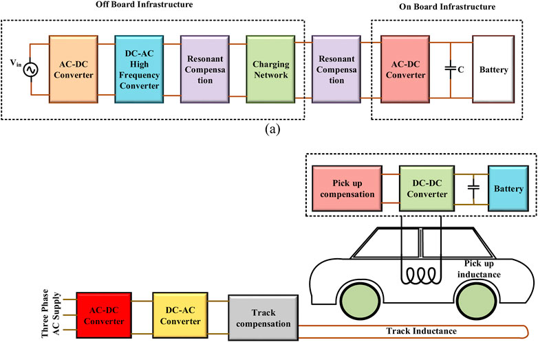
FIGURE 9. Electric car static and roadbed inductive charging.
8 Electric vehicle market
Five primary research issues are evaluated and correspond to the findings from the existing studies: 1) estimating the percentage of plug-in electric vehicles (PEVs) sold in a specific region; 2) identifying the inputs, 3) promising policies, 4) expected outcomes effects of widespread PEV market penetration 5) a new modelling strategy. Research questions about the above scenario are displayed in Figure 10 in chronological order, beginning with the most recently published. Most publications seek to identify the factors contributing to spreading PEVs in a specific market or geographic region. Research questions about adopting a new technique, with an emphasis on the methodology instead of the predicted market proliferation, often play a role. In recent years, interest has been raised in determining crucial policies and the influence of the PEV market’s spread (for instance, on the power grid). The maturation of modelling tools or the need to incorporate policy initiatives to expedite markets may account for the current emphasis on examining effects and strategies.
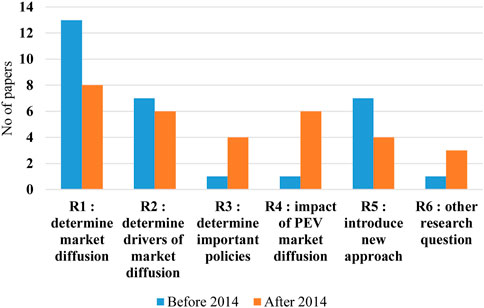
FIGURE 10. Research questions about PEV.
A straightforward classification is utilized when comparing models because the above-mentioned categories do not adequately describe most models. To show model detail, they are categorized by aggregation: 1) Very consolidated models that analyze simply the vehicle stock; 2) more differentiated methods that predict vehicle sales and distinguish several markets or customer categories; 3) the most differentiated techniques model people and integrate them for vehicle sales. Every analysis has found that by 2020, PHEVs will have captured a more significant percentage of the market than BEVs. This indicates the state of affairs in the world’s largest auto markets, where PHEVs are selling at a premium due to their more excellent range. But as battery prices continue to drop, more powerful batteries could be within reach (Nykvist and Nilsson, 2015)- (Gallagher et al., 2014). In light of this shift, several analyses (Gnann, 2015; Liu and Lin, 2017) suggest that between 2030 and 2050, BEVs will have a more significant percentage of the market than PHEVs. However, this shift in finest has to coincide with either consumers’ diminishing range concern or the capacity to recharge during long-distance travels.
As seen below, only two scenarios that project 2050 seriously consider the problems mentioned above. Both Pasaoglu et al. and Shepherd et al. omit to charge infrastructure from their model. Therefore, it cannot account for “restricted range variables” (Pasaoglu et al., 2016)- (Shepherd et al., 2012). Both studies have strong models, but these two elements will determine how quickly the BEV industry expands in the future. The emphasis on the most cost-effective option for the foreseeable is one criticism levelled at the fourth research out to 2050 (Yabe et al., 2012). It may be inaccurate to focus on price until 2050, as virtually all research on PEV market spread includes combating climate change and reducing GHG emissions as critical drivers of PEV industry diffusion. Although BEV market shares may rise significantly in the long run, projections beyond the next few years are highly dependent on several factors. Four groupings of qualities are included in the simulations to look at the specific characteristics more carefully and to develop recommendations for future modelling attempts: Considerations unique to PEVs include, but are not limited to, the following: (1) elements directly connected to the purchasing decision; (2) vehicle qualities that are included in the models; (3) characteristics to define customer traits; and (4) aspects specifically relevant for PEVs.
9 Repercussions of electric vehicle charging infrastructure
This section investigates the various electric grid components affected by EV chargers and discusses efforts to mitigate these effects.
9.1 Effects of utilizing alternative energy sources
Renewable energy sources are challenging for utilities to incorporate because of their intermittent nature. Still, advances in PEC and high-energy-density storage systems have resolved the problem of inconsistent power and made it less complicated to link EV chargers (Yabe et al., 2012). Wind energy resources that are linked to the utility grid are susceptible to being dispatched. It regulates the flow of energy when an electric vehicle is being charged or discharged. This approach is provided as an alternative. A similar strategy may be found in (FraukeHeider, 2009), which details an investigation into how to keep the power constant at the feeder while linking it to both electric vehicles and renewable sources (El Chehaly et al., 2009). The successful functioning of an isolated grid is demonstrated (Pecas Lopes et al., 2009). About 59% of the total utility grid generation capacity is accounted for by wind energy in this analysis, which involves 323 EVs (Xin et al., 2009; Bedir et al., 2010; Gamboa et al., 2010). Research demonstrating the viability of solar-powered EV charging is reported (Xin et al., 2009). This research accounts for the typical 40-mile commute that North Americans do in their SUVs daily.
9.2 Effects on the reliability of the power system
Since many power grids are already suffering on the edge of instability, a stability study must be performed before increasing the electric vehicles. The EV demand is must be modelled as a continuous power demand, with the resistive load to identify the utility grid’s reliability. The research concludes that modelling Electric vehicle charging stations as the constant resistance load since the integral to maintaining is higher, when the EV is treated as a continuous power load (Das and Aliprantis, 2008). Also, modelling EV chargers as the steady impedance load is preferable with artificial intelligence algorithms because the firm reliance is increased (Jingyu et al., 2010). The stability of the IEEE-24 bus system is analyzed with the aid of EVs employed as a power source (V2G mode), and it is observed that the usage of EVs as a power source assists in increasing the system’s stability. So, it follows that EVs are better for the utility system’s stability while they’re the power supply, but they can cause significant problems when they’re the load (El Chehaly et al., 2009).
9.3 Effects of source harmonics on the power system
The power electronics that are a part of the electric vehicle charger directly influence the harmonics that are produced by the charger. An elementary investigation has revealed that the design of the electric vehicle chargers is to blame for introducing a particular harmonic order into the electrical grid. The electric grid has demonstrated that it typically incorporates odd-order harmonics into its operations (Bradley, 1981). An investigation describes the design of electric vehicle chargers, which include regulated rectifiers and flattening line current inductors (Orr et al., 1982). Adjusting the control angle of the rectifiers demonstrates that it is possible to diminish or even eliminate the presence of the third harmonic in the line current. The architecture of the chargers at each of the 26 distinct charging stations is analyzed. The results demonstrate that the total harmonic distortion (THD) in the line current can range from 10% to 100%, depending on the architecture of the charger (Karady et al., 1994). Harmonics are introduced into the line current by electric vehicle chargers that are available for purchase, and the range of these harmonics is around 7%–99%. In addition, the results of this study indicate that it is possible to incorporate approximately fifty percent of EVs into the system without going over the voltage harmonics limit if capacitor banks are utilized. However, if capacitor banks are not utilized, it is only possible to incorporate thirty percent of EVs into the system (Staats, 1997). The dropout voltage of a transformer occurs primarily due to a decrease in its original current. It mainly relies on the amount of time the charging process is allowed to take. The total harmonic distortion of the line current has a quadratic relationship with the transformer’s lifespan. The lifespan of a transformer is not significantly impacted when the THD is maintained between 25 and 30 percent of the total output.
9.4 Effects of losses on the power system
When electric vehicle load is incorporated into the existing distribution system, the losses in the power system are another significant factor to consider. During the off-peak charging time, the system experiences losses of around 40% when there is a penetration of EV load of 62%. It has also been demonstrated that the system’s losses are proportional to the amount of EV demand and are not contingent on the geographic location (Bradley, 1981). The higher the load from electric vehicles, the higher the current in the system. As a result, the system sufferes from higher the losses across all utility system components, including transmission lines, transformers, etc.
10 Birds view
Initially, a motor provides propulsion in EVs rather than a mechanical or hydraulic shaft. Increasing the efficiency of a hybrid electric vehicle (HEV) can be achieved by carefully considering the optimal ICE and fuel cell or battery combination. PECs play an essential role in maximizing efficiency in the battery or fuel mode by making the right power converter choice. The input power and load requirements determine which converters are used. The number of components, control methods, and EMI effects all affect how well PEC works.
A critical factor in EVs’ reliability is their electrical system’s longevity. Consistently regulating the charging and discharging level with the aid of the voltage controller boosts the battery’s lifetime. Semiconductor components determine how long PEC will last. The converter must be able to withstand excessive vibration and temperature. The difficulties arise when deciding on a converter that meets all your needs simultaneously: it must be very efficient, highly rigid, cheap, and compact.
One of the most challenging trends in today’s vehicle system is the need for rapid and highly effective industrial motion control. High performance in EVs is accomplished by combining the PE method with digital signal processing.
Modern electric vehicles place greater emphasis on passenger conveniences. There is a specific minimum voltage requirement for each use case. Whether a multistage or multioutput DC-DC converter, it is a power source for DC appliances with varying ratings. The 3-ϕ inverter supplies energy to the AC load.
Traction motor health monitoring is as important as power conversion and propulsion regulation for spotting problems like faulty stators, rotors, and bearings. There is a need for robust actuators in advanced EVs to power systems like ABS and airbags. Future EVs may have better built-in safety measures thanks to the PEC with the DSP method.
The expense of the electrical system in EVs is defined by the number of inverter units and components used. The higher the luxury load, the more PEC is required to propel the car. The difficulty is reducing the vehicle’s price by deciding on fewer power conversion units to handle more opulent loads.
11 Conclusion
The purpose of this concise study is to supply readers with more recent data on studies involving EV adoption with RE systems. Electric vehicles (EVs) have a lot of potentials to be the future of transportation and a saviour from the looming tragedies caused by global warming. The following recommendations are also provided for resolving the issues highlighted by this analysis.
• V2G is a prospective method that allows idle or parked EVs to act as dispersed resources that may store or generate power at suitable periods, allowing the grid and EV to interchange power.
• Improving asymmetric estimating methods and variable extraction approaches is essential for their usefulness in practice, accountability, and computing performance.
• To ensure long-term profitability and environmentally benign transportation, governments in practically all industrialized countries continually create new legislation to promote EV use.
• Battery life may be improved for many uses by developing estimation algorithms.
• The pace at which the EV battery may be charged or discharged is slow because of the power constraint of traditional silicon devices.
• The demand for faster and more powerful charging methods and more advanced inductive charging technology will increase as battery capacities increase.
This study addresses the currently available and commonly used architectures with back-to-back ac/dc/dc converters, constructions with multiple dc ports and a shared ac connection, and constructions without an isolation transformer. These buildings may be further classified by whether they use conductive or inductive charging. In addition, several forms of energy used by these structures are extensively outlined. This study delves deeply into several essential topics, including their adverse effects on renewable energy resources, the stability of the utility grid, the supply and demand balance, the assets of the utility system, voltage and phase, the current harmonics of the utility grid, and the utility system losses.
Data availability statement
The raw data supporting the conclusions of this article will be made available by the authors, without undue reservation.
Author contributions
All authors listed have made a substantial, direct, and intellectual contribution to the work and approved it for publication.
Funding
This work was supported in part by the Government of India, Department of Science and Technology (DST), Research Board (SERB) Core Research, under Grant CRG/2020/004073.
Conflict of interest
The authors declare that the research was conducted in the absence of any commercial or financial relationships that could be construed as a potential conflict of interest.
Publisher’s note
All claims expressed in this article are solely those of the authors and do not necessarily represent those of their affiliated organizations, or those of the publisher, the editors and the reviewers. Any product that may be evaluated in this article, or claim that may be made by its manufacturer, is not guaranteed or endorsed by the publisher.
References
Abboud, K., Omar, H. A., and Zhuang, W. (2016). Interworking of DSRC and cellular network technologies for V2X communications: A survey. IEEE Trans. Veh. Technol. 65 (12), 9457–9470. doi:10.1109/tvt.2016.2591558
AdamsKlobodu, S. E. K. M., and Apio, A. (2018). Renewable and non-renewable energy, regime type and economic growth. Renew. Energy 125, 755–767. doi:10.1016/j.renene.2018.02.135
Aggeler, D., Canales, F., Zelaya-De La Parra, H., Coccia, A., Butcher, N., and Apeldoorn, O. (2010). “Ultra-fast DC-charge infrastructures for EV-mobility and future smart grids,” in 2010 IEEE PES innovative smart grid technologies conference europe (ISGT europe) (gothenberg: IEEE), 1e8.
Ahmadi, M., Mithulananthan, N., and Sharma, R. (2015). “Dynamic load control at a bidirectional DC fast charging station for PEVs in weak AC grids,” in 2015 IEEE PES asia-pacific power and energy engineering conference (APPEEC) (brisbane: IEEE), 1e5. QLD.
Ahmed, I., Ismail, M. H., and Hassan, M. S. (2019). Video transmission using device-to-device communications: A survey. IEEE Access 7, 131019–131038. doi:10.1109/access.2019.2940595
Amjadi, Z., and Williamson, S. S. (2010). A novel control technique for a switched-capacitor-converter-based hybrid electric vehicle energy storage system. IEEE Trans- actions Industrial Electron. 57 (3), 926–934. doi:10.1109/tie.2009.2032196
Amjadi, Z., and Williamson, S. S. (2010). Power-electronics-based solutions for plug-in hybrid electric vehicle energy storage and management systems. IEEE Trans. Industrial Electron. 57 (2), 608–616. doi:10.1109/tie.2009.2032195
Arancibia, A., and Strunz, K. (2012). “Modeling of an electric vehicle charging station for fast DC charging,” in 2012 IEEE international electric vehicle conference (greenville, SC, 1e6.
Babaei, E., Zarbil, M. S., and Asl, E. S. (2019). A developed structure for DC–DC quasi-Z-source converter with high voltage gain and high reliability. J. Circuits Syst. Comput. 28 (01), 1950012. doi:10.1142/s0218126619500129
Bai, S., and Lukic, S. (2011). “Design considerations for DC charging station for plug-in vehicles,” in 2011 IEEE vehicle power and propulsion conference (chicago, IL, 1e6.
Bai, S., and Lukic, S. M. (2013). Unified active filter and energy storage system for an MW electric vehicle charging station. IEEE Trans. Power Electron Dec 28, 579312–585803. doi:10.1109/tpel.2013.2245146
Bai, S., Yu, D., and Lukic, S. (2010). “Optimum design of an EV/PHEV charging station with DC bus and storage system,” in 2010 IEEE energy conversion CongreCss and exposition (atlanta, ga, 1178e84.
Barkas, D. A., Ioannidis, G. C., Psomopoulos, C. S., Kaminaris, S. D., and Vokas, G. A. (2020). Brushed dc motor drives for industrial and automobile applications with emphasis on control techniques: A comprehensive review. Electronics 9, 887. doi:10.3390/electronics9060887
Bedir, A., Ozpineci, B., and Christian, J. E. (2010). “The impact of plug-in hybrid electric vehicle interaction with energy storage and solar panels on the grid for a zero energy house,” in Transmission and Distribution Conference and exposition (IEEE PES), 1e6.
Bharathidasan, M., Indragandhi, V., Suresh, V., Jasiński, M., and Leonowicz, Z. (2022). A review on electric vehicle: Technologies, energy trading, and cyber security. Energy Rep. 8 (2022), 9662–9685. doi:10.1016/j.egyr.2022.07.145
Bradley, W. G. (1981). “Electric vehicle battery charger-power line interface,” in Southeastcon '81. Conference proceedings, 430e4.
Bryan, E., Sid-Ahmed, M., and Narayan, C. (2015). A comparative study ofpower supply architectures in wireless EV charging systems. IEEE Trans. Power Electron 30 (11), 6408–6422. doi:10.1109/tpel.2015.2440256
Budhia, J. B. M., and Covic, G. “A new IPT magnetic coupler for electric vehicle charging systems,” in IECON proceedings (industrial electronics conference), 2487e2492.
Busari, S. A., Khan, M. A., Huq, K. M. S., Mumtaz, S., and Rodriguez, J. (2019). Millimetre-wave massive MIMO for cellular vehicle to infrastructure communication. IET Intell. Transp. Syst. 13 (6), 983–990. doi:10.1049/iet-its.2018.5492
Cabezuelo, D., Andreu, J., de Alegría, I. M., and Robles, S. (2017). “Powertrain systems of electric, hybrid and fuel-cell vehicles: State of the technology,” in Proceedings of the IEEE 26th international symposium on industrial electronics (ISIE) (IEEE), 1445–1450.
Chan, C. C., and Chau, K. T. (1997). An overview of power electronics in electric vehicles. IEEE Trans. Industrial Electron. 44 (1), 3–13. doi:10.1109/41.557493
Chen, Nan, Wang, M., Zhang, N., Shen, X. S., and Zhao, D. (2017). SDN-based framework for the PEV integrated smart grid. IEEE Netw. 31 (2), 14–21. doi:10.1109/mnet.2017.1600212nm
Chen, Z. S. W., Liu, C., Lee, C., and Shan, Z. (2016). Cost-effectiveness comparison of coupler designs of wireless power transfer for electric vehicle dynamic charging. Energies 9 (11), 906. doi:10.3390/en9110906
Choubey, A., and Lopes, L. A. C. (2017). “A tri-state 4-switch bi-directional converter for in-terfacing supercapacitors to DC micro-grids,” in Proceedings of the IEEE 8th international symposium on power electronics for distributed generation systems (PEDG) (IEEE), 1–6.
Chung, H. S. H., Chow, W. C., Hui, S. Y. R., and Lee, S. T. S. (2000). Development of a switched-capacitor DC-DC converter with bidirectional power flow. IEEE Trans. Circuits Syst. I Fundam. Theory Appl. 47 (9), 1383–1389. doi:10.1109/81.883334
Crosier, R., Wang, S., and Jamshidi, M. A. (2012). “4800-V grid-connected electric vehicle charging station that provides STACOM-APF functions with a bi-directional, multi-level, cascaded converter,” in 2012 twenty-seventh annual IEEE applied power electronics conference and exposition (APEC) (orlando, FL: IEEE), 1508e15.
Dagdougui, H., Ouammi, A., and Dessaint, L. A. (2019). Peak load reduction in a smart building integrating microgrid and V2B-based demand response scheme. IEEE Syst. J. 13 (3), 3274–3282. doi:10.1109/jsyst.2018.2880864
Dai, P., Liu, K., Wu, X., Liao, Y., Lee, V. C. S., and Son, S. H. (2018). Bandwidth efficiency and service adaptiveness oriented data dissemination in heterogeneous vehicular networks. IEEE Trans. Veh. Technol. 67 (7), 6585–6598. doi:10.1109/tvt.2018.2812742
Das, T., and Aliprantis, D. C. (2008). “Small-signal stability analysis of power system integrated with PHEVs,” in Energy 2030 conference (IEEE), 1e4. ENERGY 2008.
Di Napoli, A., Crescimbini, F., Solero, L., Caricchi, F., and Capponi, F. G. (2002). “Multiple-input DC-DC power con-verter for power-flow management in hybrid vehicles,” in Proceedings of the confer- ence record of the IEEE industry applications conference (IEEE), 1578–1585. 37th IAS Annual Meeting (Cat. No.02CH37344), 3.
Dusmez, S. (2012). Comprehensive topological analysis of conductive and inductive charging solutions for plug-in electric vehicles. IEEE Trans. Veh. Technol. 61 (8), 3475–3489. doi:10.1109/tvt.2012.2213104
El Chehaly, M., Saadeh, O., Martinez, C., and Joos, G. (2009). “Advantages and applications of vehicle to grid mode of operation in plug-in hybrid electric vehicles,” in Electrical power & energy conference (EPEC) (IEEE), 1e6.
Elnozahy, M. S., and Salama, M. (2014). A comprehensive study of the impacts of PHEVs on residential distribution networks. IEEE Trans. Sustain. Energy 5, 332–342. doi:10.1109/tste.2013.2284573
Elsayad, N., Moradisizkoohi, H., and Mohammed, O. A. (2020). A new hybrid structure of a bidirectional DC-DC converter with high conversion ratios for electric vehicles. IEEE Trans. Veh. Technol. 69 (1), 194–206. doi:10.1109/tvt.2019.2950282
Emadi, A. (2005). Handbook of automotive power electronics and motor drives. 1st ed. New York: Taylor & Francis.
Fardahar, S. M., and Sabahi, M. (2020). New expandable switched capacitor/switched-inductor high-voltage conversion ratio bidirectional DC–DC converter. IEEE Trans. Power Electron. 35 (3), 2480–2487. doi:10.1109/tpel.2019.2932325
Fontaras, G., Grigoratos, T., Savvidis, D., Anagnostopoulos, K., Luz, R., Rexeis, M., et al. (2016). An experimental evaluation of the methodology proposed for the monitoring and certification of CO2 emissions from heavy-duty vehicles in Europe. Energy 102, 354–364. doi:10.1016/j.energy.2016.02.076
Forocoches Electricos (2017). Los incentivos Al coche eléctrico están creciendo en toda europa. Europe: Forocoches Electricos.
FraukeHeider, M. B. (2009). “Vehicle to grid: Realization of power management for the optimal integration of plug-in electric vehicles into the grid,” in EVS24 international battery, hybridand fuel cell electric vehicle symposium stavanger (Norway, 1e12.
Gallagher, K. G., Goebel, S., Greszler, T., Mathias, M., Oelerich, W., Eroglu, D., et al. (2014). Quantifying the promise of lithium–air batteries for electric vehicles. Energy Environ. Sci. 7 (5), 1555–1563. doi:10.1039/c3ee43870h
Gamboa, G., Hamilton, C., Kerley, R., Elmes, S., Arias, A., Shen, J., et al. (2010). “Control strategy of a multi-port, grid connected, direct-DC PV charging station for plug-in electric vehicles,” in Energy ConversionCongress and exposition (ECCE) (IEEE), 1173e7.
Gjelaj, M., Træholt, C., Hashemi, S., and Andersen, P. B. (2017). “Optimal design of DC fastcharging stations for EVs in low voltage grids,” in 2017 IEEE transportation electrification conference and expo (ITEC) (chicago, IL, 684e9.
Gnann, T. (2015). Market diffusion of plug-in electric vehicles and their charging infrastructure. Germany: Fraunhofer-Verlag Stuttgart.
Gryparis, E., Papadopoulos, P., Leligou, H. C., and Psomopoulos, C. S. (2020). Electricity demand and carbon emission in power generation under high penetration of electric vehicles. A European Union perspective. A Eur. Union perspect. Energy Rep. 6 (6), 475–486. doi:10.1016/j.egyr.2020.09.025
Hannan, M. A., Ali, J. A., Mohamed, A., and Hussain, A. (2018). Optimization techniques to enhance the performance of induction motor drives: A review. Renew. Sustain. Energy Rev. 81, 1611–1626. doi:10.1016/j.rser.2017.05.240
Introduction, A. (2014). Installation guide for electric vehicle supply equipment. Massachusetts: Evse.
Islam, F., and Pota, H. (2013). Plug-in-hybrid electric vehicles park as virtual DVR. Electron. Lett. 49, 211–213. doi:10.1049/el.2012.3569
Islam, F. R., and Cirrincione, M. (2016). Vehicle to grid system to design a centre node virtual unified power flow controller. Electron. Lett. 52, 1330–1332. doi:10.1049/el.2016.0534
Jafri, N. H., and Gupta, S. (2016). “An overview of fuel cells application in transportation,” in Proceedings of the IEEE transportation electrification conference and expo (IEEE).
Jingyu, Y., Xu, G., Qian, H., and Xu, Y. (2010). “Battery fast charging strategy based on model predictive control,” in Vehicular technology conference fall (VTC 2010-fall) (IEEE 72nd), 1e8.
Joy, T., Thirugnanam, K., and Kumar, P. (2013). “A multi-point Bidirectional Contactless Charging System in a charging station suitable for EVs and PHEVs applications,” in 2013 annual IEEE India conference (INDICON) (Mumbai: IEEE), 1e6.
Kanamarlapudi, V. R. K., Wangenfei, B., Kandasamy, N. K., and So, P. L. (2018). A new ZVS full-bridge DC–DC converter for battery charging with reduced losses over full-load range. IEEE Trans. Ind. Appl. 54 (1), 571–579. doi:10.1109/tia.2017.2756031
Karady, G. G., Berisha, S. H., Blake, T., and Hobbs, R. (1994). “Power quality problems at electric vehicle's charging station,” in International congress & exposition, february 1994, session. (MI, USA: International Congress & Exposition Detroit).
Khalid, M. R., Alam, M. S., Sarwar, A., and Jamil Asghar, M. S. (2019). A Comprehensive review on electric vehicles charging infrastructures and their impacts on power-quality of the utility grid. eTransportation 1, 100006. doi:10.1016/j.etran.2019.100006
Khaligh, A. (2008). “A multiple-input dc-dc positive buck-boost converter topology,” in Proceedings of the Twenty-third annual IEEE applied power electronics conference and exposition (IEEE), 1522–1526. doi:10.1109/APEC.2008.4522926
Khaligh, A., and Dusmez, S. (2012). Comprehensive topological analysis of conductive and inductive charging solutions for plug-in electric vehicles. IEEE Trans. Veh. Technol. 61 (8), 3475e3489.
Khaligh, A., and Li, Z. (2010). Battery, ultracapacitor, fuel cell, and hybrid energy storage systems for electric, hybrid electric, fuel cell, and plug-in hybrid electric vehicles: State of the Art. IEEE Trans. Veh. Technol. 59 (6), 2806–2814. doi:10.1109/tvt.2010.2047877
KhanAhmedHusain, M. A. A. I., Sozer, Y., and Badawy, M. (2015). Performance analysis of bidirectional DC–DC converters for electric vehicles. IEEE Trans. Industry Appl. 51 (4), 3442–3452. doi:10.1109/tia.2015.2388862
Kosmanos, D., Maglaras, L. A., Mavrovouniotis, M., Moschoyiannis, S., Argyriou, A., Maglaras, A., et al. (2018). Route optimization of electric vehicles based on dynamic wireless charging. IEEE Access 6, 42551–42565. doi:10.1109/access.2018.2847765
Kumar, L., and Jain, S. (2014). Electric propulsion system for electric vehicular technology: A review. Renew. Sustain. Energy Rev. 29, 924–940. doi:10.1016/j.rser.2013.09.014
Lan, Y., Benomar, Y., Deepak, K., Aksoz, A., Baghdadi, M. E., Bostanci, E., et al. (2021). Switched reluctance motors and drive systems for electric vehicle powertrains: State of the art analysis and future trends. Energies 14 (8), 2079. doi:10.3390/en14082079
Lee, W-S., Kim, J. H., Lee, J-Y., and Lee, I-O. (2019). Design of an isolated DC/DC topology with high efficiency of over 97% for EV fast chargers. IEEE Trans. Veh. Technol. 68 (12), 11725–11737. doi:10.1109/tvt.2019.2949080
Lee, Y. S., and Chiu, Y. Y. (2005). Zero-current-switching switched-capacitor bidirec-tional DC-DC converter. Proc. IEE Electr. power Appl. 152, 1525–1530. doi:10.1049/ip-epa:20050138
Li, Z. C. S., Liu, Z., Zhao, H., Zhu, L., Shuai, C., and Chen, Z. (2016). Wireless power transfer by electric field resonance and its application in dynamic charging. ’” IEEE Trans. Ind. Electron 63, 6602–6612. doi:10.1109/tie.2016.2577625
Liu, C., and Lin, Z. (2017). How uncertain is the future of electric vehicle market: Results from Monte Carlo simulations using a nested logit model. Int. J. Sustain Transp. 11 (4), 237–247. doi:10.1080/15568318.2016.1248583
Lulhe, A. M., and Date, T. N. (2015). “A technology review paper for drives used in electrical vehicle (EV) & hybrid electrical vehicles (HEV),” in proceedings of the international conference on control, instrumentation, communication and computational technologies (ICCI- CCT) (IEEE), 632–636.
Mamun, K. A., Islam, F. R., Haque, R., Chand, A. A., Prasad, K. A., Goundar, K. K., et al. (2022). Systematic modeling and analysis of on-board vehicle integrated novel hybrid renewable energy system with storage for electric vehicles. Sustainability 14 (5), 2538. doi:10.3390/su14052538
Marchesoni, M., and Vacca, C. (2007). New DC-DC converter for energy storage system interfacing in fuel cell hybrid electric vehicles. IEEE Trans. Power Electron. 22 (1), 301–308. doi:10.1109/tpel.2006.886650
MartmezMartinez-Salamero, L., Calvente, J., Giral, R., Poveda, A., and Fossas, E. (1998). Analysis of a bidirectional coupled-inductor cuk converter operating in sliding mode. IEEE Trans. Circuits Syst. Fundam. Theory Appl. 45, 355–363. doi:10.1109/81.669058
Miller, O. C. O. J. M., Jones, P., Li, J. M., and Onar, O. C. (2015). ORNL experience and challenges facing dynamic wireless power charging of EV's. ’” IEEE Circuits Syst. Mag. 15 (2), 40–53. doi:10.1109/mcas.2015.2419012
Mirzaei, A., Jusoh, A., Salam, Z., Adib, E., and Farzanehfard, H. (2010). “Analysis and design of a high efficiency bidirectional DC-DC converter for battery and ultracapacitor applications,” in 2010 IEEE International Conference on Power and Energy (IEEE), 803–806.
Momete, D. C. (2018). Analysis of the potential of clean energy deployment in the European Union. IEEE Access 6, 54811–54822. doi:10.1109/access.2018.2872786
Morrow, K. U. S. (2008). Department of energy vehicle technologies program e advanced vehicle testing activity plug-in hybrid electric vehicle charging infrastructure review, 58517.
Naghizadeh, N., and Williamson, S. S. (2013). “A comprehensive review of power electronic converter topologies to integrate photovoltaics (PV), AC grid, and electric vehicles,” in Proceedings of the IEEE Transportation Electrification Conference and Expo (ITEC) (IEEE), 1–6.
Naik, G., Choudhury, B., and Park, J-M. (2019). IEEE 802.11bd & 5G NR V2X: Evolution of radio access technologies for V2X communications. IEEE Access 7, 70169–70184. doi:10.1109/access.2019.2919489
Najafi, A., Jasinski, M., et al. (2021a). “A distributed framework for optimal operation of EV aggregators problem,” in 2021 IEEE International Conference on Environment and Electrical Engineering and 2021 IEEE Industrial and Commercial Power Systems Europe, EEEIC/I & CPS Europe (IEEE), 1–5.
Navarro, G., Francisco, J., Yebra, L. J., and MedinaGomezGimenez-Fernandez, F. J. A. (2020). DC-DC linearized converter model for faster simulation of lightweight urban electric vehicles. IEEE Access 8, 85380–85394. doi:10.1109/access.2020.2992558
Ni, L., Patterson, D. J., and Hudgins, J. L. (2012). High power current sensorless bidirectional 16-phase interleaved DC-DC converter for hybrid vehicle application. IEEE Trans. Power Electron. 27 (3), 1141–1151. doi:10.1109/tpel.2011.2165297
Nunes, P., Figueiredo, R., and Brito, M. C. (2016). The use of parking lots to solar-charge electric vehicles. Renew. Sustain. Energy Rev. 66, 679–693. doi:10.1016/j.rser.2016.08.015
Nykvist, B., and Nilsson, M. (2015). Rapidly falling costs of battery packs for electric vehicles. Nat. Clim. Change 5 (4), 329–332. doi:10.1038/nclimate2564
OnarKobayashi, O. C. J., and Khaligh, A. (2013). A fully directional universal power electronic interface for EV, HEV, and PHEV applications. IEEE Trans. Power Electron. 28 (12), 5489–5498. doi:10.1109/tpel.2012.2236106
Onwuchekwa, C. N., and Kwasinski, A. (2011). “Analysis of boundary control for a multi-ple-input DC-DC converter topology,” in Proceedings of the 26th annual IEEE applied power electronics conference and exposition (APEC) (IEEE), 1232–1237.
Orr, J. A., Emanuel, A. E., and Pileggi, D. G. (1982). in Current harmonics, voltage distortion, and powers associated with battery chargers Part I: comparisons among different types of chargers, PAS-101. Power Apparatus and Systems (IEEE Transactions on), 2703e10.
Pasaoglu, G., Harrison, G., Jones, L., Hill, A., Beaudet, A., and Thiel, C. (2016). A system dynamics based market agent model simulating future powertrain technology transition: Scenarios in the EU light duty vehicle road transport sector. Technol. Forecast Soc. Change 104, 133–146. doi:10.1016/j.techfore.2015.11.028
Pecas Lopes, J. A., Rocha Almeida, P. M., and Soares, F. J. (2009). “Using vehicle-to-grid to maximize the integration of intermittent renewable energy resources in islanded electric grids,” in Clean electrical Power,2009 international conference on (IEEE), 290e5.
Plug-in electric vehicle (2013). Plug-in electric vehicle handbook for public charging station hosts. Washington, D.C: U.S department of energy.
Prakash, K., Ali, M., Siddique, M. N. I., Chand, A. A., Kumar, N. M., Dong, D., et al. (2022). A review of battery energy storage systems for ancillary services in distribution grids: Current status, challenges and future directions. Front. Energy Res. 10, 971704. doi:10.3389/fenrg.2022.971704
Rawson, M. K. S. (1999). “Electric vehicle charging equipment design and health and safety codes,” in SAE technical paper 1999-01-2941. doi:10.4271/1999-01-2941
Reed, G. F., Grainger, B. M., Sparacino, A. R., Kerestes, R. J., and Korytowski, M. J. (2012). Advancements in medium voltage DC architecture development with applications for powering electric vehicle charging stations. Cleveland, OH: IEEE Energytech, 1e8.
Rivera, S., and Wu, B. (2017). Electric vehicle charging station with an energy storage stage for split-DC bus voltage balancing. IEEE Trans. Power Electron March 32, 2376–2386. doi:10.1109/tpel.2016.2568039
Rivera, S., Wu, B., Kouro, S., Yaramasu, V., and Wang, J. (2015). Electric vehicle charging station using a neutral point clamped converter with bipolar DC bus. IEEE Trans. Ind. Electron April. 62, 1999–2009. doi:10.1109/tie.2014.2348937
Shakeri, M., Shayestegan, M., Reza, S. S., Yahya, I., Bais, B., Akhtaruzzaman, M., et al. (2018). Implementation of a novel home energy management system (HEMS) architecture with solar photovoltaic system as supplementary source. Renew. Energy 125, 108–120. doi:10.1016/j.renene.2018.01.114
Sharma, A., and Sharma, S. (2019). Review of power electronics in vehicle-to-grid systems. J. Energy Storage 21, 337–361. doi:10.1016/j.est.2018.11.022
Shepherd, S., Bonsall, P., and Harrison, G. (2012). Factors affecting future demand for electric vehicles: A model based study. Transp. Policy 20, 62–74. doi:10.1016/j.tranpol.2011.12.006
Staats, P. T. (1997). “The harmonic impact of electric vehicle battery charging,” in Faculty of the graduate school. vol. Doctor of Philosophy Austin (Texas: The university of Texas), 195.
Sun, B., Dragi_cevi_c, T., Freijedo, F. D., Vasquez, J. C., and Guerrero, J. M. (2016). A control algorithm for electric vehicle fast charging stations equipped with flywheel energy storage systems. IEEE Trans. Power Electron Sept. 31, 6674–6685. doi:10.1109/tpel.2015.2500962
Sun, X., Shi, Z., Lei, G., Guo, Y., and Zhu, J. (2019a). Analysis and design optimization of a permanent magnet synchronous motor for a campus patrol electric vehicle. IEEE Trans. Veh. Technol. 68 (11), 10535–10544. doi:10.1109/tvt.2019.2939794
Vasiladiotis, M., Rufer, A., and B_eguin, A. (2012). “Modular converter architecture for medium voltage ultra fast EV charging stations: Global system considerations,” in 2012 IEEE international electric vehicle conference (greenville, SC: IEEE), 1e7.
Verma, A., and Singh, B. (2019). Multi-objective reconfigurable three-phase off-board charger for EV. IEEE Trans. Ind. Appl. 55 (4), 4192–4203. doi:10.1109/tia.2019.2908950
Vu, V., Tran, D., and Choi, W. (2018). Implementation of the constant current and constant voltage charge of inductive power transfer systems with the double-sided LCC compensation topology for electric vehicle battery charge applications. IEEE Trans. Power Electron Sept. 33, 73989–77410. doi:10.1109/tpel.2017.2766605
Waffler, S., and Kolar, J. W. (2009). A novel low-loss modulation strategy for high-power bidirectional buck ${\bm +}$ boost converters. IEEE Trans. Power Electron. 24 (6), 1589–1599. doi:10.1109/tpel.2009.2015881
Waltrich, G., Duarte, J. L., and Hendrix, M. A. M. (2012). Multiport converter for fast charging of electrical vehicle battery. IEEE Trans. Ind. Appl. Nov.-Dec. 48, 2129–2139. doi:10.1109/tia.2012.2226694
Wang, Y., Su, Z., Xu, Q., Yang, T., and Zhang, N. (2019). A novel charging scheme for electric vehicles with smart communities in vehicular networks. IEEE Trans. Veh. Technol. 68 (9), 8487–8501. doi:10.1109/tvt.2019.2923851
Wu, J., Wu, Z., Wu, F., and Mao, X. (2017). A power balancing method of distributed generation and electric vehicle charging for minimizing operation cost of distribution systems with uncertainties. Energy Sci. Eng. 5 (3), 167–179. doi:10.1002/ese3.157
Wu, Q., Wang, M., Zhou, W., Wang, X., and Wang, Q. (2019). “One zero-voltage-switching voltage-fed three-phase push-pull DC/DC converter for electric vehicle applications,” in 2019 IEEE Transportation Electrification Conference and Expo (ITEC. IEEE), 1–5.
WuLuShi, H. J. W., and Xing, Y. (2012). Nonisolated bidirectional DC–DC converters with negative-coupled inductor. IEEE Trans. Power Electron. 27 (5), 2231–2235. doi:10.1109/tpel.2011.2180540
Xin, L., Lopes, L. A. C., and Williamson, S. S. (2009). “Power & energy society general meetingPES '09,” in On the suitability of plug-in hybrid electric vehicle (PHEV) charging infrastructures based on wind and solar energy (IEEE), 1e8.
Yabe, K., Shinoda, Y., Seki, T., Tanaka, H., and Akisawa, A. (2012). Market penetration speed and effects on CO2 reduction of electric vehicles and plug-in hybrid electric vehicles in Japan. Energy Policy 45, 529–540. doi:10.1016/j.enpol.2012.02.068
YangGuanZhangJiang, Y. T. S. W., and Huang, W. (2018). More symmetric four-phase inverse coupled inductor for low current ripples & high-efficiency interleaved bidirec-tional buck/boost converter. IEEE Trans. Power Electron. 33 (3), 1952–1966. doi:10.1109/tpel.2017.2745686
Yong, J. Y., Ramachandaramurthy, V. K., Tan, K. M., and Mithulananthan, N. (2015). Bi-directional elec-tric vehicle fast charging station with novel reactive power compensation for voltage regulation. Int. J. Electr. Power & Energy Syst. 64, 300–310. doi:10.1016/j.ijepes.2014.07.025
You, P., Yang, Z., Zhang, Y., Low, S. H., and Sun, Y. (2016). Optimal charging schedule for a battery switching station serving electric buses. IEEE Trans. Power Syst. 31 (5), 3473–3483. doi:10.1109/tpwrs.2015.2487273
Yu, Y., Zhao, L., and Zhou, C. (2019). Influence of rotor-bearing coupling vibration on dynamic behavior of electric vehicle driven by in-wheel motor. IEEE Access 7, 63540–63549. doi:10.1109/access.2019.2916554
Zhang, J., Pei, Y., Shen, J., Wang, L., Ding, T., and Wang, S. (2020). Charging strategy unifying spatial-temporal coordination of electric vehicles. IEEE Access 8, 74853–74863. doi:10.1109/access.2020.2987607
Keywords: electric vehicle, DC-DC converter, DC-AC converter, bidirectional converter, electric market, on-boarding charging, off-board charging
Citation: Vishnuram P, R N, P S, K V, Bajaj M, Khurshaid T, Nauman A and Kamel S (2023) A comprehensive review on EV power converter topologies charger types infrastructure and communication techniques. Front. Energy Res. 11:1103093. doi: 10.3389/fenrg.2023.1103093
Received: 19 November 2022; Accepted: 31 January 2023;
Published: 10 February 2023.
Edited by:
Constantinos S. Psomopoulos, University of West Attica, GreeceReviewed by:
George Ioannidis, University of West Attica, GreeceAneesh A. Chand, University of the South Pacific, Fiji
Copyright © 2023 Vishnuram, R, P, K, Bajaj, Khurshaid, Nauman and Kamel. This is an open-access article distributed under the terms of the Creative Commons Attribution License (CC BY). The use, distribution or reproduction in other forums is permitted, provided the original author(s) and the copyright owner(s) are credited and that the original publication in this journal is cited, in accordance with accepted academic practice. No use, distribution or reproduction is permitted which does not comply with these terms.
*Correspondence: Mohit Bajaj, thebestbajaj@gmail.com; Tahir Khurshaid, tahir@ynu.ac.kr; Ali Nauman, anauman@ynu.ac.kr