
Cost-Effectiveness Comparison of Coupler Designs of Wireless Power Transfer for Electric Vehicle Dynamic Charging


Abstract
:1. Introduction
2. Cost-Effectiveness Comparison of Basic Coupler Designs
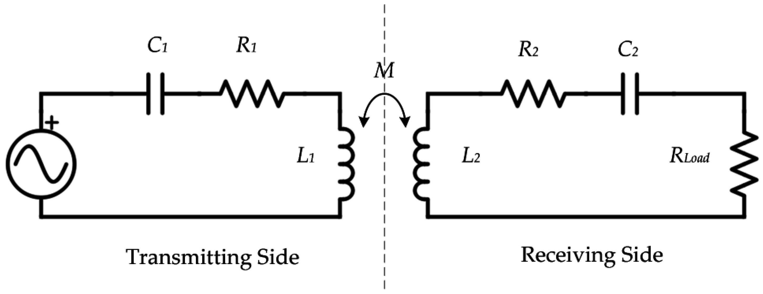
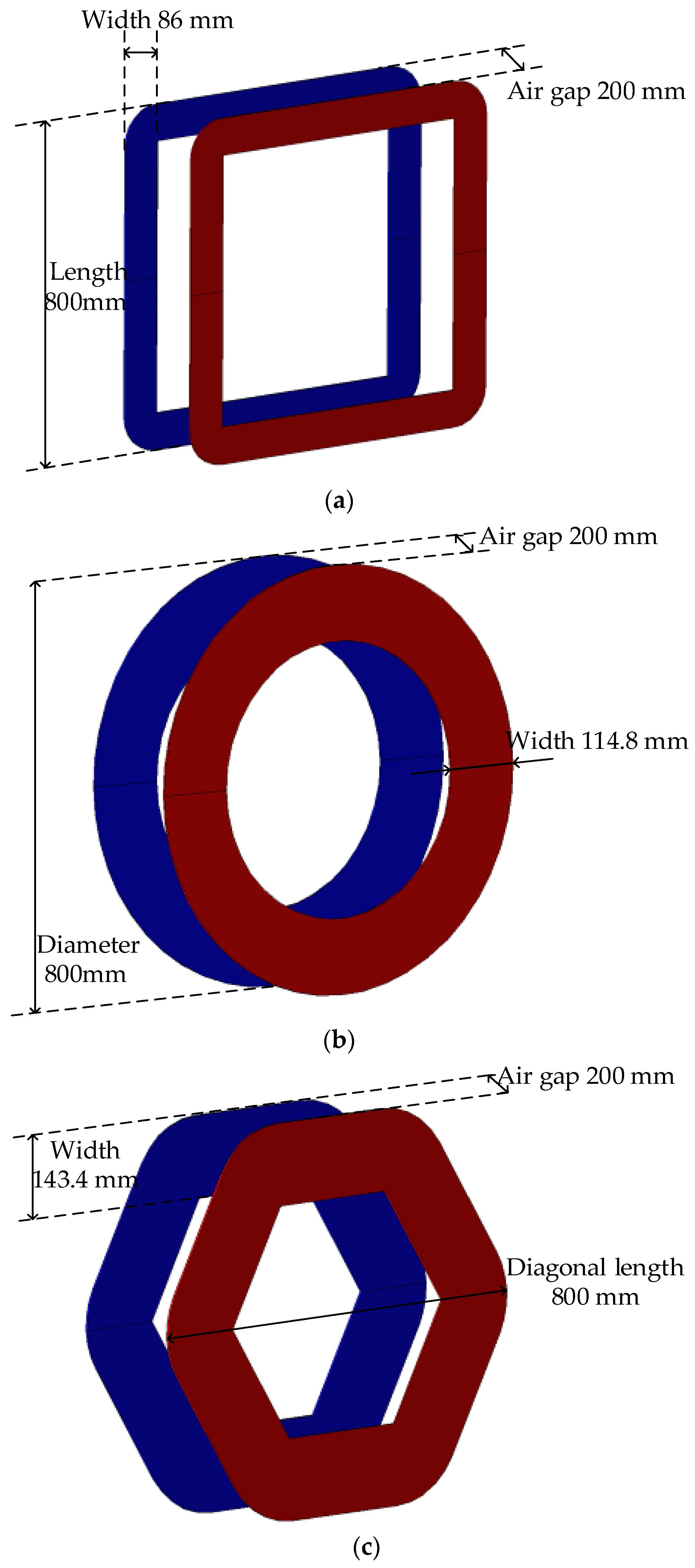
2.1. Basic Topology and Coupler Design
2.2. Comparison and Analysis
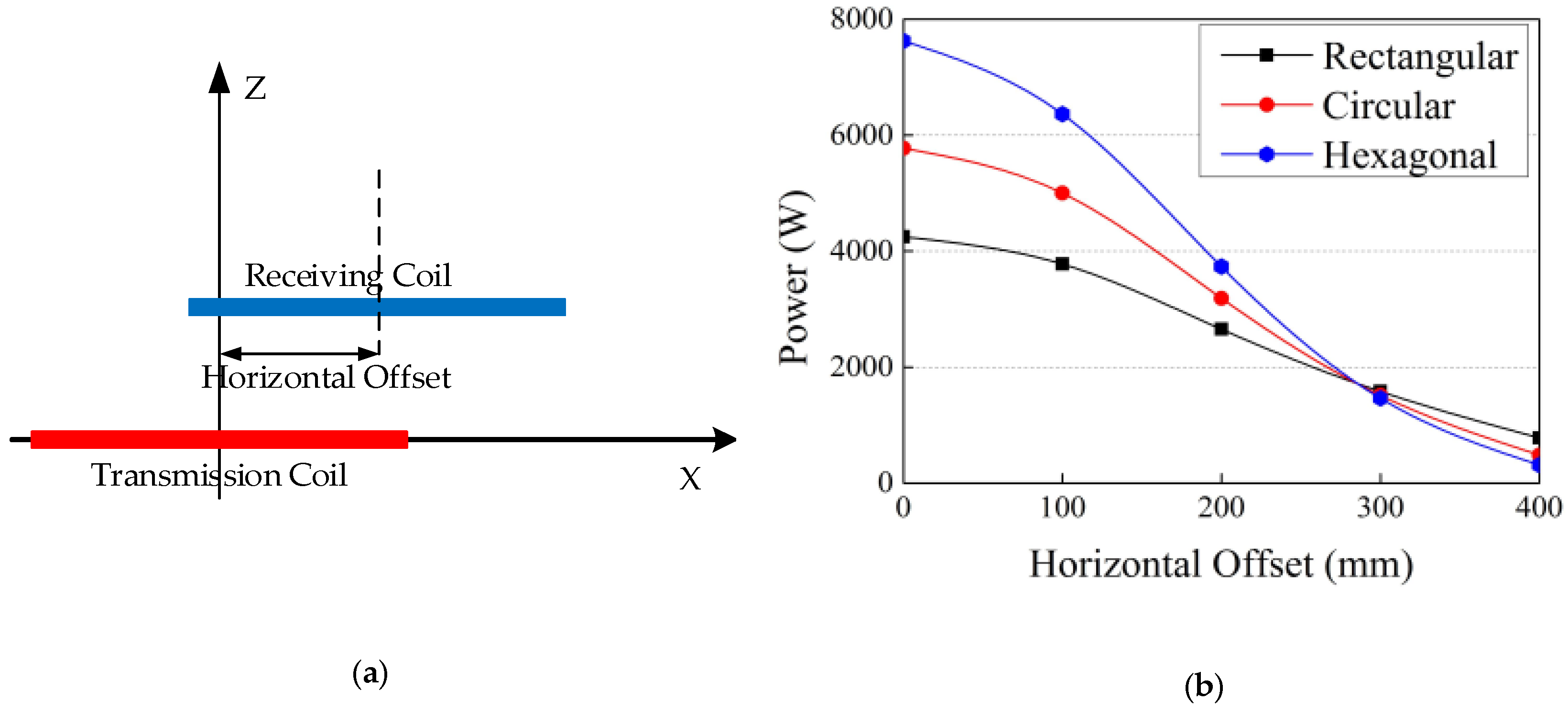
- The rectangular coil can be used as the main transmitting part for dynamic charging since it has the larger cost-effectiveness value. Namely, the rectangular coil has the better capability of transferring the power under the suitable material cost.
- The hexagonal coil can be used as the main transmitting part for the static charging since it has the larger cost-effectiveness value. On the other hand, the hexagonal coil can be used as the auxiliary part for the dynamic charging because it has the ability of concentrating the output power at a specific point.
- The circular coil has the medium value of the cost-effectiveness for the power transfer. Hence, this type of coupler is not preferred for the system installation.
- The CE equation includes the power output and the effective area, which directly relate with the charging frequency and the charging distance. When the frequency is higher, the power would be higher for the same WPT system. Also, when the distance is larger, the power would be less for the same WPT system. Actually, the CE equation is for the general cost-effectiveness estimation of a WPT system, which is independent from the charging frequency and the charging distance.
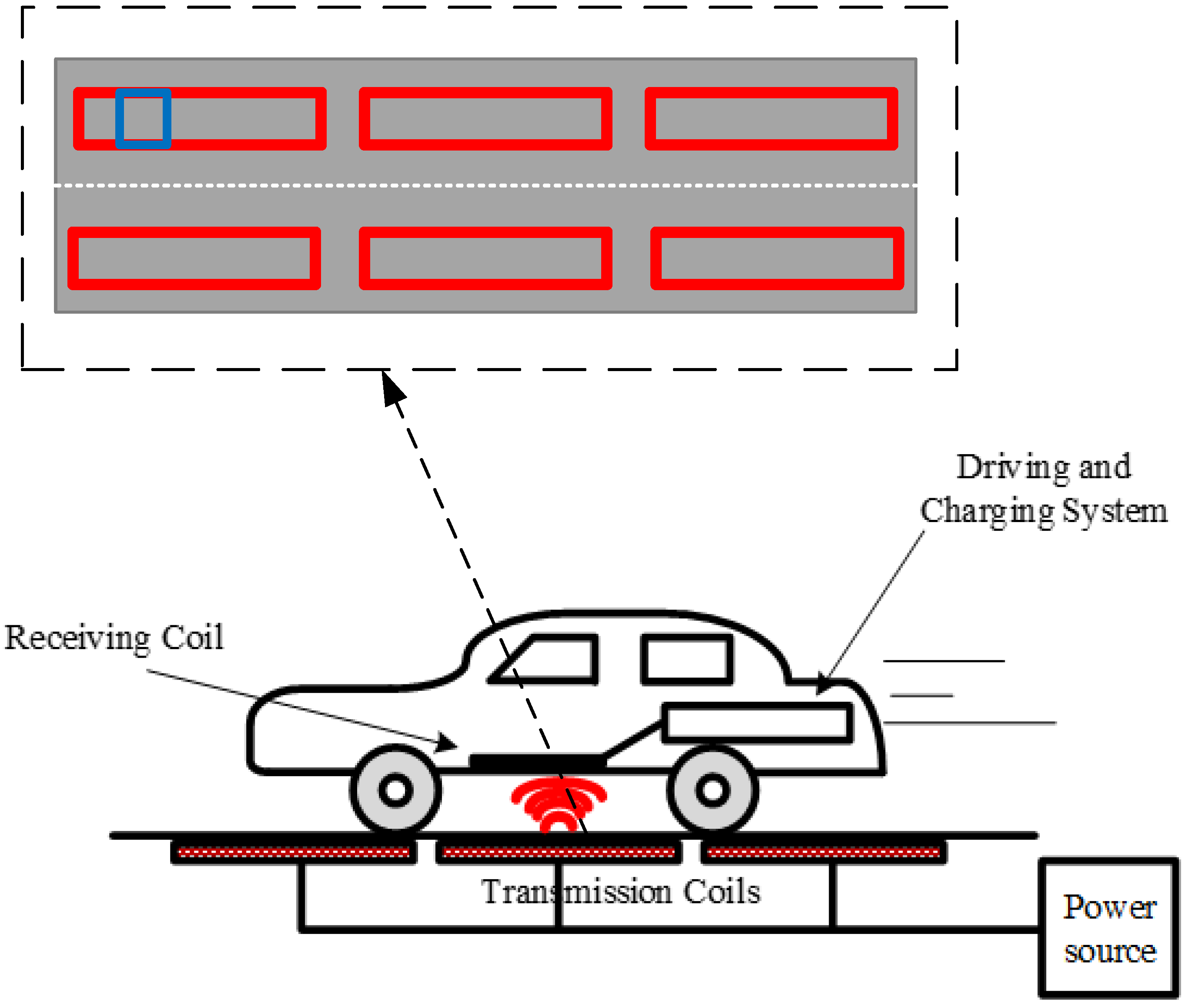
3. Proposed Dynamic Charging System
3.1. System Configuration
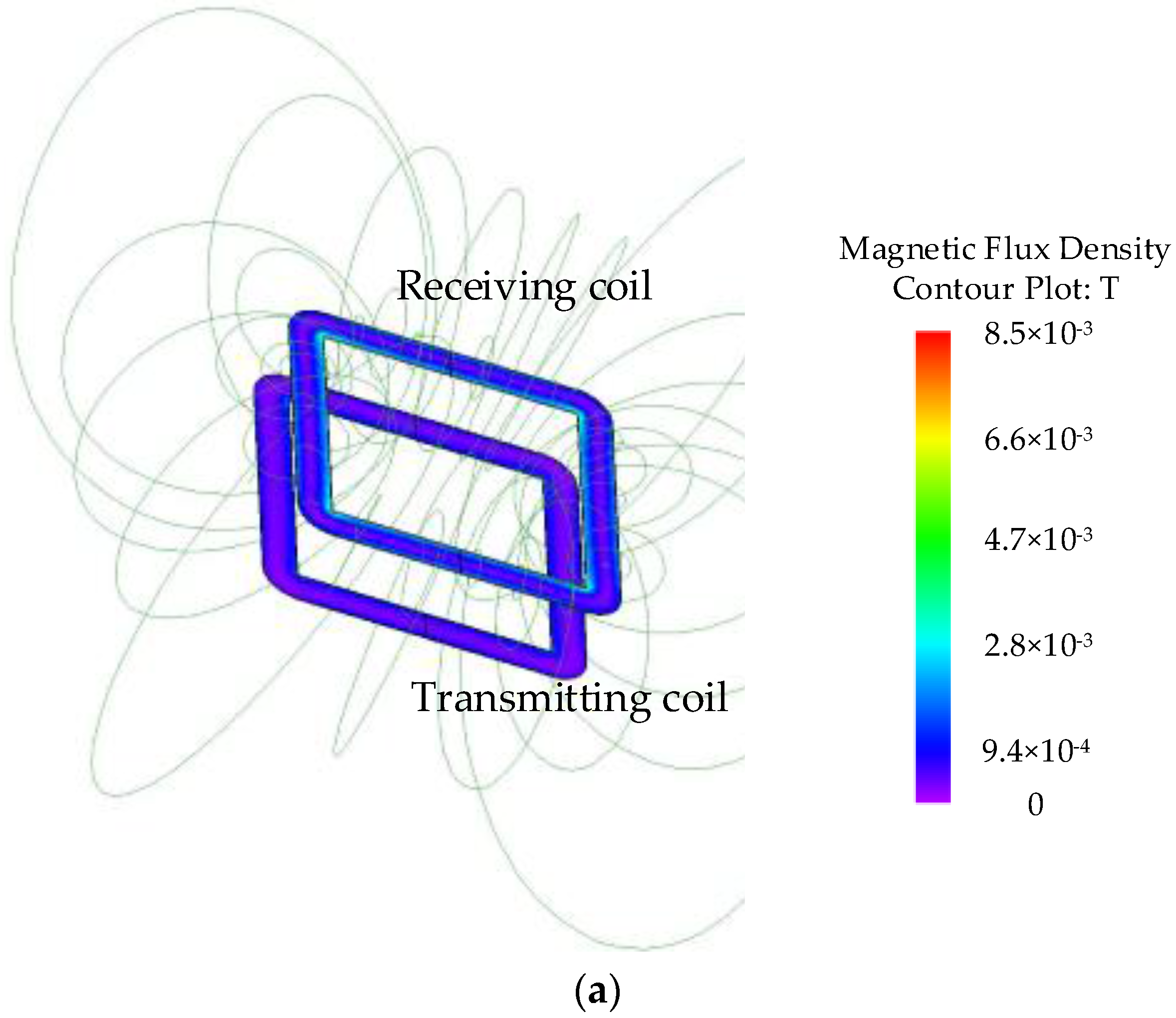
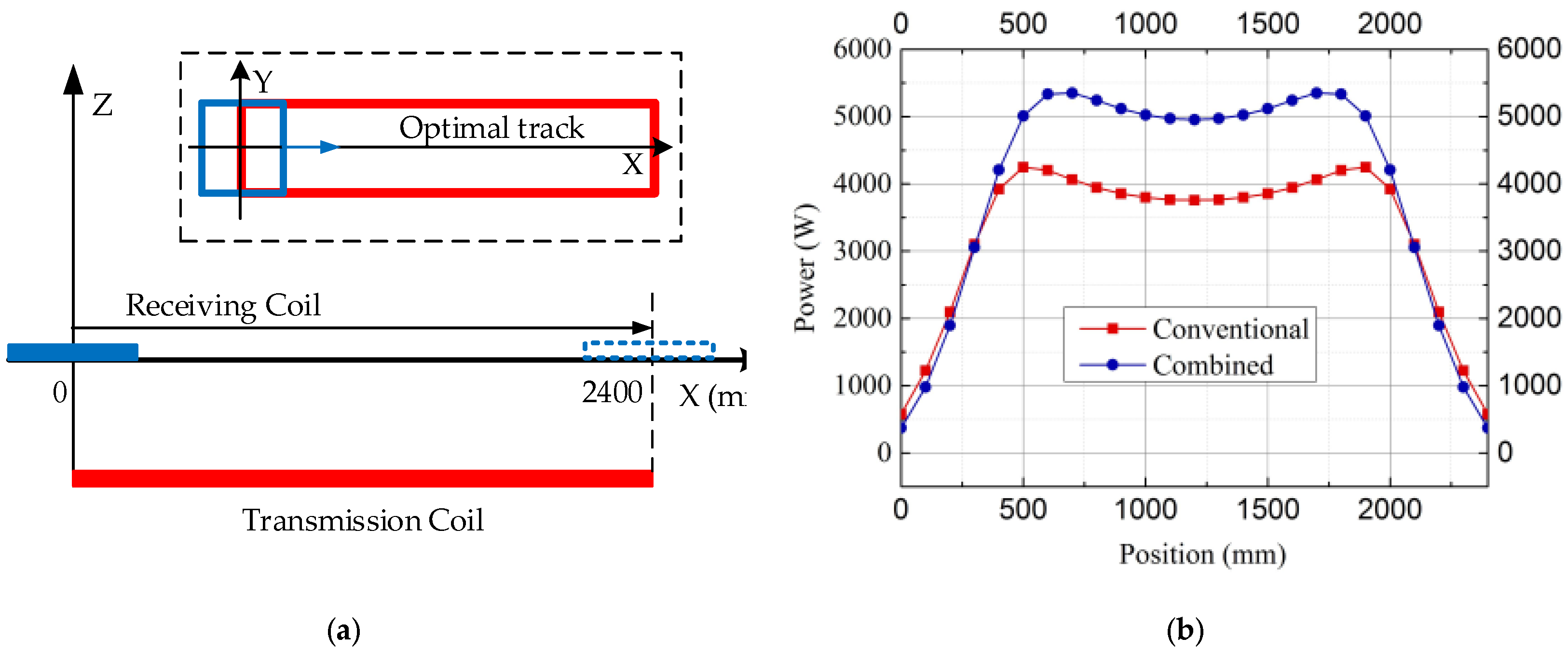
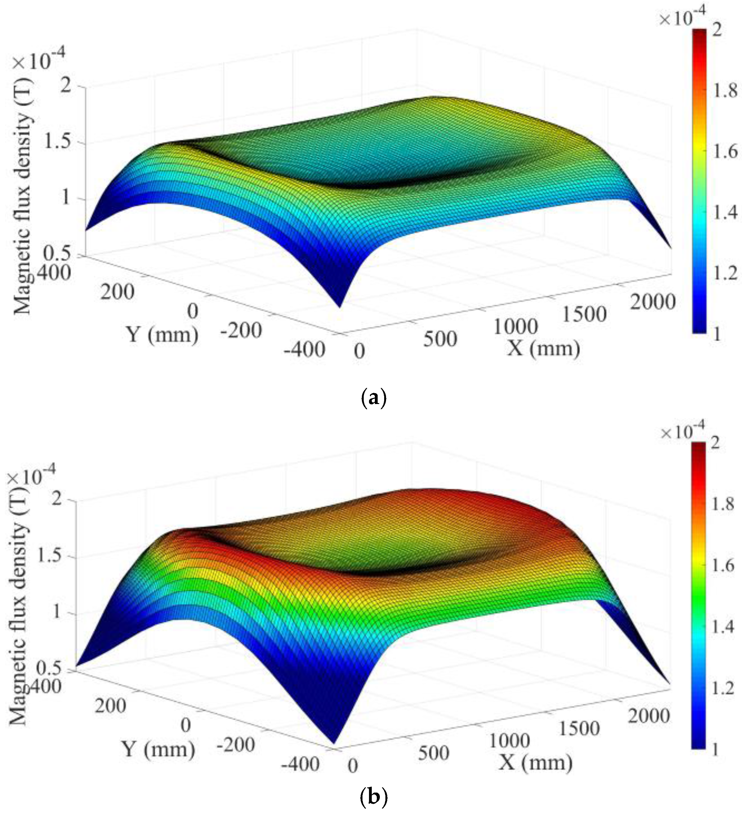
3.2. Simulation Result
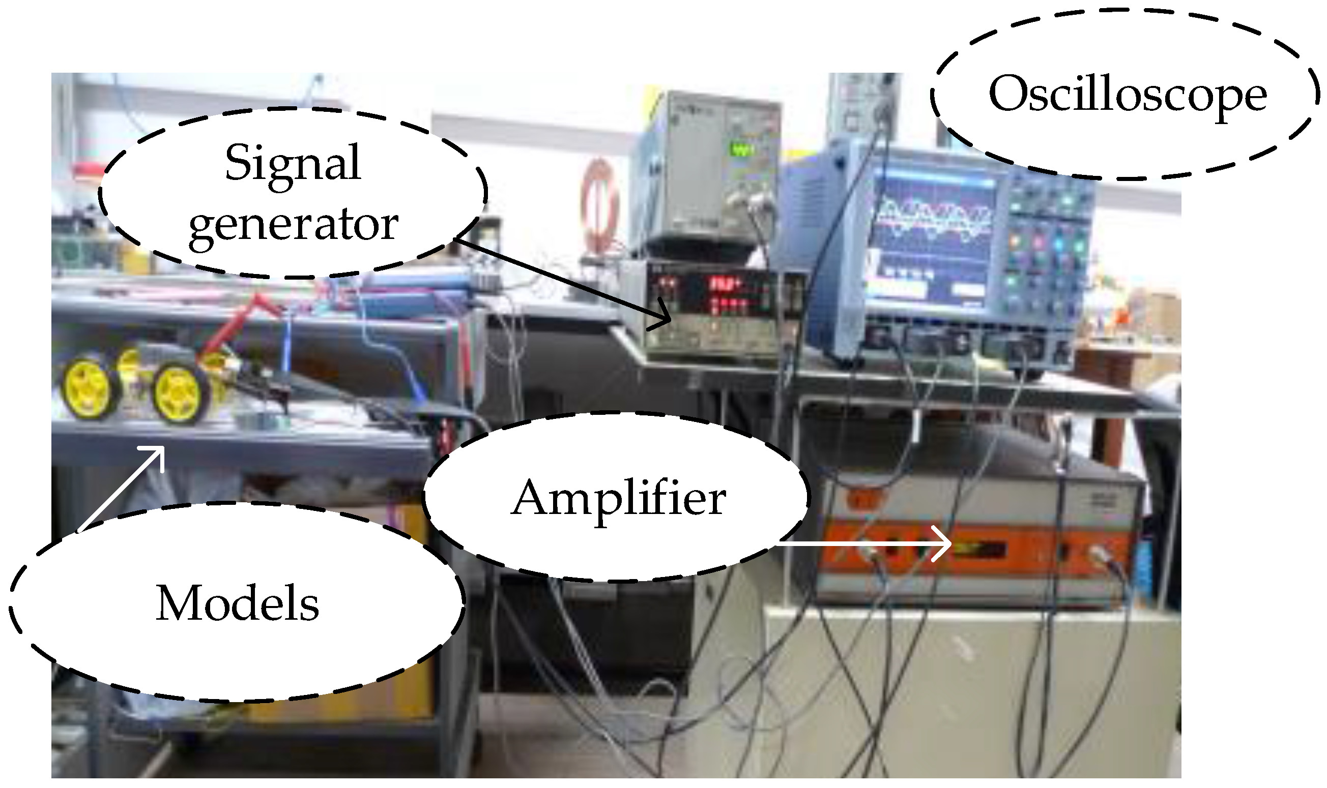
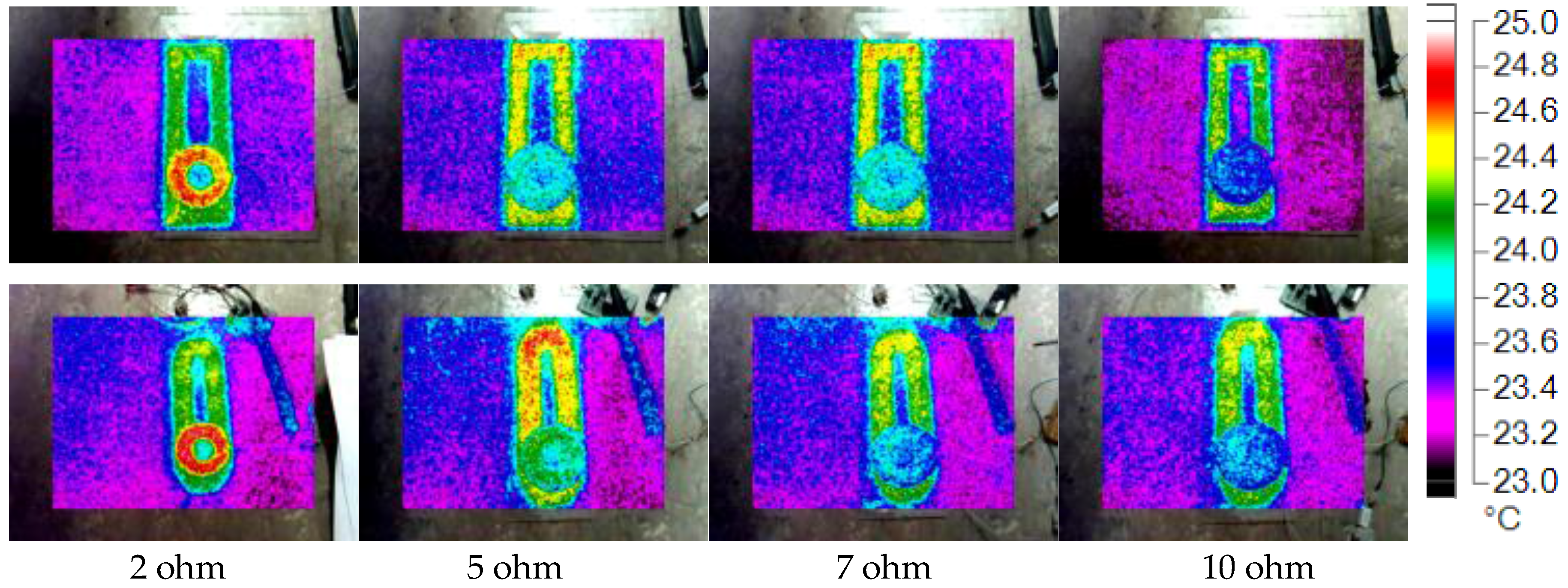
3.3. Experimentation Result
4. Conclusions
Acknowledgments
Author Contributions
Conflicts of Interest
References
- Hui, S.Y.R.; Zhong, W.; Lee, C.K. A Critical Review of Recent Progress in Mid-Range Wireless Power Transfer. IEEE Trans. Power Electron. 2014, 29, 4500–4511. [Google Scholar] [CrossRef] [Green Version]
- Lee, C.K.; Zhong, W.X.; Hui, S.Y.R. Effects of magnetic coupling of nonadjacent resonators on wireless power domino-resonator systems. IEEE Trans. Power Electron. 2012, 27, 1905–1916. [Google Scholar] [CrossRef]
- Zhang, J.; Cheng, C. Analysis and optimization of three-resonator wireless power transfer system for predetermined-goals wireless power transmission. Energies 2016, 9, 274. [Google Scholar] [CrossRef]
- Jang, Y.; Jovanović, M.M. A contactless electrical energy transmission system for portable-telephone battery chargers. IEEE Trans. Ind. Electron. 2003, 50, 520–527. [Google Scholar] [CrossRef]
- Liu, C.; Chau, K.T.; Zhang, Z.; Qiu, C.; Li, W.; Ching, T.W. Wireless power transfer and fault diagnosis of high-voltage power line via robotic bird. J. Appl. Phys. 2015, 117, 17D521. [Google Scholar] [CrossRef] [Green Version]
- Ramrakhyani, A.K.; Mirabbasi, S.; Mu Chiao, M.C. Design and optimization of resonance-based efficient wireless power delivery systems for biomedical implants. IEEE Trans. Biomed. Circuits Syst. 2011, 5, 48–63. [Google Scholar] [CrossRef] [PubMed]
- Liu, C.; Chau, K.T.; Qiu, C.; Lin, F. Investigation of energy harvesting for magnetic sensor arrays on Mars by wireless power transmission. J. Appl. Phys. 2014, 115, 2014–2017. [Google Scholar] [CrossRef] [Green Version]
- Liu, C.; Chau, K.T.; Zhang, Z.; Qiu, C.; Lin, F.; Ching, T.W. Multiple-receptor wireless power transfer for magnetic sensors charging on Mars via magnetic resonant coupling. J. Appl. Phys. 2015, 117, 17A743. [Google Scholar] [CrossRef] [Green Version]
- Chan, C.C. The state of the art of electric, hybrid, and fuel cell vehicles. IEEE Proc. 2007, 95, 704–718. [Google Scholar] [CrossRef]
- Burke, A. Batteries and Ultracapacitors for Electric, Hybrid, and Fuel Cell Vehicles. IEEE Proc. 2007, 95, 806–820. [Google Scholar] [CrossRef]
- Suh, N.P.; Cho, D.H.; Rim, C.T. Design of on-line electric vehicle (OLEV). In Global Product Development, Proceedings of the 20th CIRP Design Conference, Nantes, France, 19–21 April 2010; pp. 3–8.
- Lee, S.; Huh, J.; Park, C.; Choi, N.-S.; Cho, G.-H.; Rim, C.-T. On-Line electric vehicle using inductive power transfer system. In Proceedings of the 2010 IEEE Energy Conversion Congress and Exposition (ECCE), Atlanta, GA, USA, 12–16 September 2010; pp. 1598–1601.
- Wang, Z.; Wei, X.; Dai, H. Design and Control of a 3 kW Wireless Power Transfer System for Electric Vehicles. Energies 2015, 9, 10. [Google Scholar] [CrossRef]
- Qiu, C.; Chau, K.T.; Liu, C.; Li, W.; Lin, F. Quantitative comparison of dynamic flux distribution of magnetic couplers for roadway electric vehicle wireless charging system. J. Appl. Phys. 2014, 115, 17A334. [Google Scholar] [CrossRef] [Green Version]
- Nian, X. Pad Design for a Move-and-Charge System for Electric Vehicles. In Proceedings of the 2014 Makassar International Conference on Electrical Engineering and Informatics, Makassar, Indonesia, 26–30 November 2014; pp. 97–102.
- Hui, S.Y.R.; Ho, W.W.C. A new generation of universal contactless battery charging platform for portable consumer electronic equipment. IEEE Trans. Power Electron. 2005, 20, 620–627. [Google Scholar] [CrossRef]
- Budhia, M.; Boys, J.T.; Covic, G.A.; Huang, C.Y. Development of a single-sided flux magnetic coupler for electric vehicle IPT charging systems. IEEE Trans. Ind. Electron. 2013, 60, 318–328. [Google Scholar] [CrossRef]
- Wang, C.-S.; Stielau, O.H.; Covic, G.A. Design Considerations for a Contactless Electric Vehicle Battery Charger. IEEE Trans. Ind. Electron. 2005, 52, 1308–1314. [Google Scholar] [CrossRef]
- Shin, J.; Shin, S.; Kim, Y.; Ahn, S.; Lee, S.; Jung, G.; Jeon, S.-J.; Cho, D.H. Design and Implementation of Shaped Magnetic Resonance Based Wireless Power Transfer System for Roadway-Powered Moving Electric Vehicles. IEEE Trans. Ind. Electron. 2014, 61, 1179–1192. [Google Scholar] [CrossRef]
- Zhang, Z.; Chau, K.T.; Liu, C.; Li, F.; Ching, T.W. Quantitative Analysis of Mutual Inductance for Optimal Wireless Power Transfer via Magnetic Resonant Coupling. IEEE Trans. Magn. 2014, 50, 1–4. [Google Scholar] [CrossRef] [Green Version]
- Thai, V.X.; Choi, S.Y.; Choi, B.H.; Kim, J.H.; Rim, C.T. Coreless Power Supply Rails Compatible with both Stationary and Dynamic Charging of Electric Vehicles. In Proceedings of the 2015 IEEE 2nd International Future Energy Electronics Conference (IFEEC), Kaohsiung, Taiwan, 1–4 November 2015.
- Yilmaz, M.; Buyukdegirmenci, V.T.; Krein, P.T. General design requirements and analysis of roadbed inductive power transfer system for dynamic electric vehicle charging. In Proceedings of the 2012 IEEE Transportation Electrification Conference and Expo (ITEC), Dearborn, MI, USA, 18–20 June 2012; pp. 1–6.
- Throngnumchai, K.; Hanamura, A.; Naruse, Y.; Takeda, K. Design and Evaluation of a Wireless Power Transfer System with Road Embedded Transmitter Coils for Dynamic Charging of Electric Vehicles. In Proceedings of the 2013 World Electric Vehicle Symposium and Exhibition (EVS27), Barcelona, Spain, 17–20 November 2013; pp. 1–10.


| Item | Rectangular | Circular | Hexagonal |
|---|---|---|---|
| Effective length | 800 mm | 800 mm | 800 mm |
| Coil width | 86 mm | 114.8 mm | 143.4 mm |
| Number of turns | 21 | 28 | 35 |
| Thickness | 4 mm | 4 mm | 4 mm |
| Primary current (AMS) | 10 A | 10 A | 10 A |
| Air gap length | 200 mm | 200 mm | 200 mm |
| Operating frequency | 35 kHz | 35 kHz | 35 kHz |
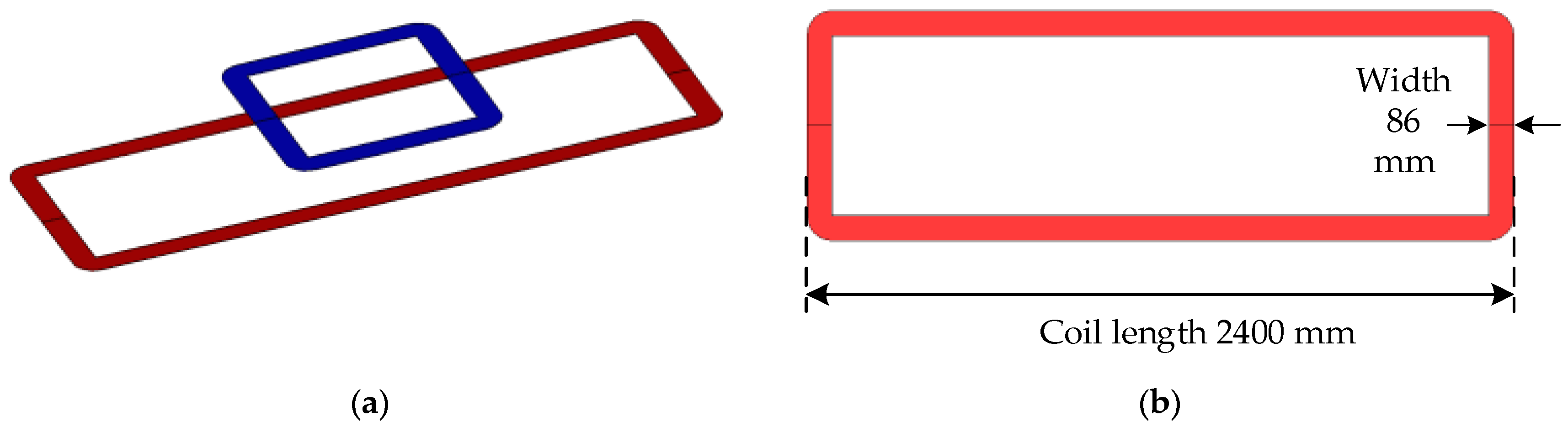
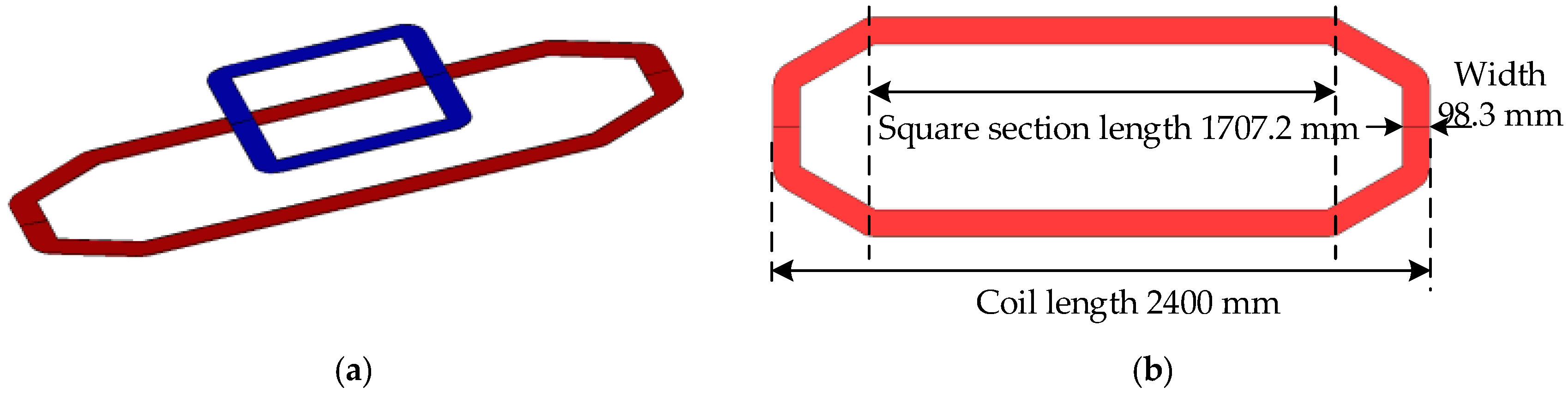
| Item | Conventional Type | Combined Type |
|---|---|---|
| Total length | 2400 mm | 2400 mm |
| Coil width | 86 mm | 98.3 mm |
| Number of turns | 21 | 24 |
| Thickness | 4 mm | 4 mm |
| Primary current (AMS) | 10 A | 10 A |
| Air gap length | 200 mm | 200 mm |
| Operating frequency | 35 kHz | 35 kHz |
| Item | Conventional Transmitting Coil | Combined Transmitting Coil | Receiving Coil |
|---|---|---|---|
| Coil length | 240 mm | 240 mm | 80 mm |
| Coil width | 25.5 mm | 30.4 mm | 25.5 mm |
| Number of turns | 21 | 25 | 21 |
| Thickness | 1.2 mm | 1.2 mm | 1.2 mm |
| Inductance | 0.0967 mH | 0.1022 mH | 0.02784 mH |
| Capacitance | 220 nF | 204 nF | 746 nF |
| Resistance | 0.4059 ohm | 0.407 ohm | 0.1435 ohm |
© 2016 by the authors; licensee MDPI, Basel, Switzerland. This article is an open access article distributed under the terms and conditions of the Creative Commons Attribution (CC-BY) license (http://creativecommons.org/licenses/by/4.0/).
Share and Cite
Chen, W.; Liu, C.; Lee, C.H.T.; Shan, Z. Cost-Effectiveness Comparison of Coupler Designs of Wireless Power Transfer for Electric Vehicle Dynamic Charging. Energies 2016, 9, 906. https://doi.org/10.3390/en9110906
Chen W, Liu C, Lee CHT, Shan Z. Cost-Effectiveness Comparison of Coupler Designs of Wireless Power Transfer for Electric Vehicle Dynamic Charging. Energies. 2016; 9(11):906. https://doi.org/10.3390/en9110906
Chicago/Turabian StyleChen, Weitong, Chunhua Liu, Christopher H.T. Lee, and Zhiqiang Shan. 2016. "Cost-Effectiveness Comparison of Coupler Designs of Wireless Power Transfer for Electric Vehicle Dynamic Charging" Energies 9, no. 11: 906. https://doi.org/10.3390/en9110906