Abstract
In both industrial and educational settings, efficient handling of products from Plastic Injection Machines is crucial for precise and stable system operation. Enhancements in the design and production processes, achieved through the implementation of a Four Axis (4D) BOM type Cartesian System, lead to significant improvements in cost-effectiveness and product quality. In this study focuses on optimizing system operations, including rotational movements and the operation of the vertical cylinder through forward-backward movements. Finite element analysis is employed to investigate potential issues arising from shape changes in the mechanical structure due to dynamic loads on the plate joint connections. By addressing these concerns during the design phase through simulation, mechanical structure errors are eliminated, resulting in improved system performance.
Highlights
- Structural resilience under dynamic loads
- Contribution to industrial automation and efficiency
- Optimizing automated unloading
1. Introduction
The contemporary development of production systems has been influenced by innovative techniques [1]. This development has been closely aligned with the widespread adoption of lean manufacturing practices [2], flexible manufacturing systems [3], Cartesian robots [4], as well as methodologies like layered production techniques [5], digital mirroring [6], and factory simulation [7]. These approaches have enabled the production of complex products with low tolerances [8].
Plastic Injection Machines play a pivotal role in enhancing productivity, aiming for swift production [9]. These machines consist of male and female molds that enclose to produce plastic-based products [11]. Once the production process is completed, and the male mold is opened [12], the products are ready for retrieval from the female mold [13]. The rapid retrieval of items from the female mold is crucial to promptly close the molds and commence the production of new items [14]. The closure of the male mold involves high forces [15], rendering the manual retrieval of items from the female mold extremely perilous [16]. Therefore, for both safety and production capacity considerations, this operation necessitates automation [17-19]. Given its multifaceted motion requirements, including the retrieval of plastic items from the male mold and their placement on an external conveyor [20], Cartesian Robots emerge as a highly suitable solution [21].
Opting for a Cartesian Robot solution offers several noteworthy advantages [22-26]. These robots are mounted atop the machine chassis, directly above the stationary female mold, thereby minimizing the total spatial footprint compared to articulated robots. Unlike articulated robots, which typically require horizontal assembly adjacent to the machine, Cartesian Robots predominantly utilize vertical space, which is often readily available above plastic injection machines. Articulated robots are usually positioned in front of the machine’s sliding door, entering the machine to retrieve items from the female mold, thus occupying horizontal space. Conversely, Cartesian Robots make efficient use of vertical space and seldom pose spatial constraints, as factory heights typically accommodate both the Cartesian Robot and the machine itself [27]. Additionally, Cartesian Robots, assembled with axes stacked one atop the other, offer ease of sub-component replacement and cost-effective repairs in comparison to articulated robots [28-30].
Cartesian Robots are mostly gantries where axes are mounted one by one on top of each other to obtain the final structure. Due to this fact, sub-components are easy to replace and cheaper to repair compared to articulated robots [28-30].
The implementation of a Cartesian Robot solution satisfactorily fulfills the safety and capacity augmentation requirements of unloading Plastic Injection Machines. It eliminates the need for human labor, mitigating the risk of injuries. The Cartesian Robot's software employs safety sensors to ensure the orderly execution of movements, thereby safeguarding the robot, the front end, and the male and female molds from any potential damage. In this study, we delve into the design and production parameters of the 4-Axis Plastic Injection Discharge System tailored for industrial applications.
2. Methods
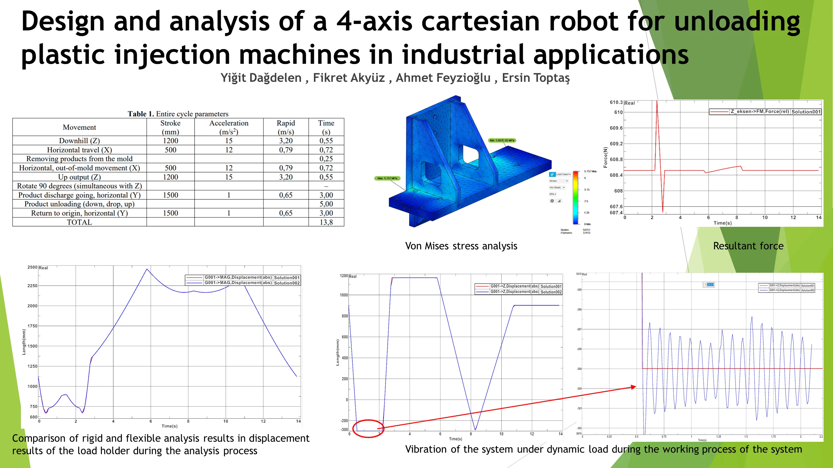
This study investigates the design and manufacturing parameters of the Four-Axis Plastic Injection Discharge System (4-Axis PIEDS) tailored for industrial applications. The fundamental requirement driving the development of this system is the expeditious and secure removal of products from plastic injection machines, aimed at enhancing system precision and stability. The complete cycle time is delineated as per Table 1. Furthermore, all data and system analyses were conducted utilizing the NX software program.
Table 1Entire cycle parameters
Movement | Stroke (mm) | Acceleration (m/s2) | Rapid (m/s) | Time (s) |
Downhill (Z) | 1200 | 15 | 3,20 | 0,55 |
Horizontal travel (X) | 500 | 12 | 0,79 | 0,72 |
Removing products from the mold | 0,25 | |||
Horizontal, out-of-mold movement (X) | 500 | 12 | 0,79 | 0,72 |
Up output (Z) | 1200 | 15 | 3,20 | 0,55 |
Rotate 90 degrees (simultaneous with Z) | – | |||
Product discharge going, horizontal (Y) | 1500 | 1 | 0,65 | 3,00 |
Product unloading (down, drop, up) | 5,00 | |||
Return to origin, horizontal (Y) | 1500 | 1 | 0,65 | 3,00 |
TOTAL | 13,8 |
In this analysis, we embark on an examination of the dynamic movements that comprise the specified operational cycle of the system. The operational cycle involves a sequence of movements, which are as follows: the vertical descent down along the Z-Axis, movement along the approach axis toward the mold on the X-Axis, material removal from the mold, exit along the approach axis away from the mold on the X-Axis, maximum dynamic ascent, closure of the Injection Machine mold, disposal of the products extracted from the mold outside the machine through combined Y-Axis and Z-Axis motion, and finally, the return to the new product pick point along the Y-Axis.
Subsequent to the assessment of the mechanical system design and the analysis of these dynamic movements, a comprehensive finite element analysis was conducted. This analysis aimed to scrutinize the structural integrity and strength of the system’s design. Consequently, the analytical focus was dedicated to addressing several critical issues, including the modeling and refinement of the vertical up and down movement system, the assessment of vibrations and damping characteristics exhibited during system motion, precise position determination within the motion sequence, evaluation of tip displacement magnitude following the accelerated stop at the conclusion of motion, identification of system structure and axis group deviations, and the meticulous determination of momentum loads.
Fig. 1Structural profiles and their moment of inertia values in the automation system
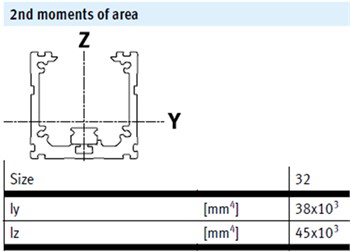
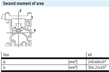
Furthermore, it is essential to note that the design incorporates specific profiles and moment of inertia values, as presented in Fig. 1, which significantly influence the system’s performance and structural stability. These parameters play a pivotal role in ensuring the system's reliability and efficiency throughout the operational cycle.
Table 2Model design technical data
Technical subtitles | Data |
Definition of total load | Vacuum gripper + plastic parts |
Total load to be carried on vertical axis | 10 kg |
Center of gravity of total load (X, Y, Z) | 0, 0, 100 mm |
External dimensions of total load (X, Y, Z) | 250, 120, 500 mm |
Center of gravity of total load (X, Y, Z) | 75, 0.150 mm |
In this context, it is imperative to emphasize that not all components within this system underwent finite element analysis; rather, the focus predominantly rested on parts where load distributions were substantial and their significance warranted closer scrutiny. Specifically, the investigation aimed to assess the system's structural integrity under dynamic loads, wherein forces exhibited variability. To achieve this objective, a meticulous examination of these components was conducted, and their response to dynamic loads was analyzed using the finite element method. This approach facilitated an in-depth exploration of the design's structural resilience and load-bearing capacity.
3. Results
As a result of the dynamic analysis of the plastic injection unloading system, the force and moment values on some critical parts were measured and strength analyzes were carried out with finite element analysis. Thus, the strength and shape changes of the designed parts were observed and the suitability of the design was investigated. As a result of the analysis, it has been seen that the safety factor is 12 at the highest strength conditions, and the design is appropriate and safe. It was observed in the FEA analyzes that the dimensions and material selections of the parts used in the system were appropriate.
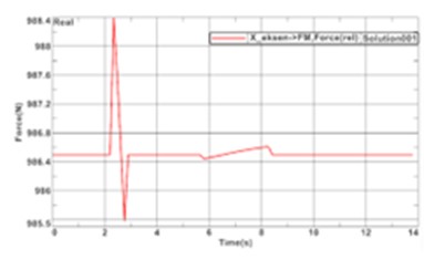
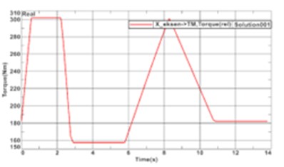
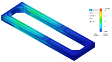
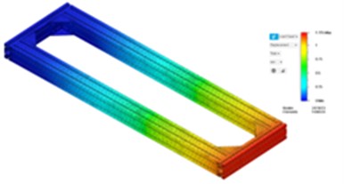
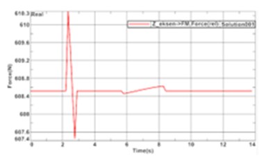
Fig. 2Analysis results of the Y-axis carrier table
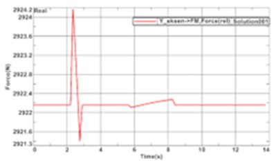
a) Resultant force
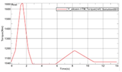
b) Resultant moment
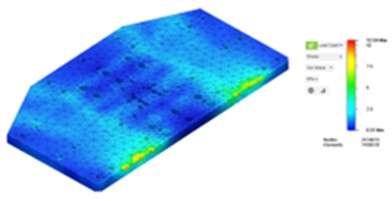
c) Von Mises stress analysis
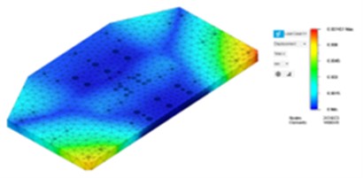
d) Shape deformation
Fig. 3Analysis results of X-axis carrier chassis
a) Resultant force
b) Resultant moment
c) Von Mises stress analysis
d) Shape deformation
In the process of taking and carrying the 100 N load carried by the automation system during the working process, the analysis was done on the analysis rigidity, as well as the flexing states of the materials were included in the analysis. Two different analyzes were made and compared in the graph given in Fig. 5. While the system in red color on the graph is accepted as rigid, in the blue color analysis, the flexibility structure of the system originating from the material was calculated and analyzed and compared. Thus, flexing conditions were observed in the holder part of the automation system during operation.
Fig. 4Analysis results of Z axis support table
a) Resultant force
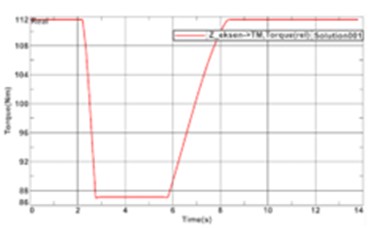
b) Resultant moment
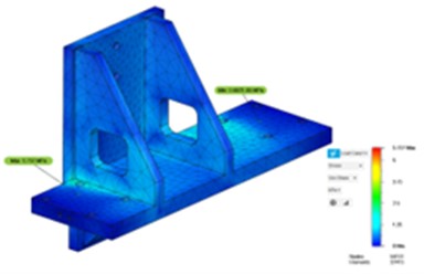
c) Von Mises stress analysis
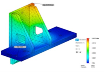
d) Shape deformation
Fig. 5Comparison of rigid and flexible analysis results in displacement results of the load holder during the analysis process
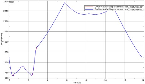
Fig. 6Vibration of the system under dynamic load during the working process of the system
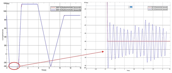
In order to reveal more clearly the observation of the deformation of the load in the material holder due to stretching, the effects of the changes along the Z axis of the holder on the rigid and flexible structure were obtained as seen in Fig. 6. It was observed that there is a total displacement of 2.8 mm when the load is taken, depending on the rigid structure of the flexing state of the system.
4. Conclusions
This study constitutes an exhaustive examination of the dynamic behaviors exhibited by a pneumatic gripper employed for the automated unloading of plastic injection parts, coupled with a comprehensive strength analysis of the gripper component. The research outcomes obtained from this investigation reveal a commendable level of operational efficiency exhibited by the gripper. Furthermore, it has been conclusively demonstrated that the gripper component exhibits the requisite structural fortitude to withstand the assessed maximum loads.
These empirical findings bear profound implications for the advancement of automation and enhanced efficiency within industrial production processes. They underscore the imperative nature of recognizing and addressing the dynamic nature of loads in engineering systems, thus emphasizing the significance of not relying solely on static evaluations. The capacity to withstand varying and dynamic loads is paramount in ensuring the reliability and longevity of automated systems, and the insights garnered from this study can serve as a valuable asset in furthering the integration of automation technology within industrial settings, thereby bolstering production processes and augmenting overall operational efficiency.
References
-
K. Ma, X. Xia, and L. Liu, “Digital finance and advanced manufacturing industry development in china: a coupling coordination analysis,” Sustainability, Vol. 15, No. 2, p. 1188, Jan. 2023, https://doi.org/10.3390/su15021188
-
O. Ülkir, I. Ertuğrul, S. Ersoy, and B. C. Girgin, “Material transfer optimization in lean manufacturing,” (in Turkish), Osmaniye Korkut Ata Üniversitesi Fen Bilimleri Enstitüsü Dergisi, Vol. 2, No. 1, pp. 74–78, 2019.
-
A. Yadav and S. C. Jayswal, “Modelling of flexible manufacturing system: a review,” International Journal of Production Research, Vol. 56, No. 7, pp. 2464–2487, 2018.
-
J. Lettori, R. Raffaeli, P. Bilancia, M. Peruzzini, and M. Pellicciari, “A review of geometry representation and processing methods for cartesian and multiaxial robot-based additive manufacturing,” The International Journal of Advanced Manufacturing Technology, Vol. 123, No. 11-12, pp. 3767–3794, Dec. 2022, https://doi.org/10.1007/s00170-022-10432-8
-
D. Khorsandi et al., “Manufacturing of microfluidic sensors utilizing 3D printing technologies: a production system,” Journal of Nanomaterials, Vol. 2021, pp. 1–16, Aug. 2021, https://doi.org/10.1155/2021/5537074
-
M. M. Rathore, S. A. Shah, D. Shukla, E. Bentafat, and S. Bakiras, “The role of AI, machine learning, and big data in digital twinning: a systematic literature review, challenges, and opportunities,” IEEE Access, Vol. 9, pp. 32030–32052, 2021, https://doi.org/10.1109/access.2021.3060863
-
Nancy Lyons, “Deep learning-based computer vision algorithms, immersive analytics and simulation software, and virtual reality modeling tools in digital twin-driven smart manufacturing,” Economics, Management, and Financial Markets, Vol. 17, No. 2, pp. 67–81, 2022.
-
B. Ekinli, M. Kaba, and S. Ersoy, “Manufacturing of complex geometric structure metal matrix structures used for special purposes,” Journal of Mechatronics and Artificial Intelligence in Engineering, Vol. 2, No. 2, pp. 96–101, Dec. 2021, https://doi.org/10.21595/jmai.2021.22335
-
V. Re, “Shedding light on the invisible: addressing the potential for groundwater contamination by plastic microfibers,” Hydrogeology Journal, Vol. 27, No. 7, pp. 2719–2727, Nov. 2019, https://doi.org/10.1007/s10040-019-01998-x
-
F. J. G. Silva et al., “A novel automated system for the handling of car seat wires on plastic over-injection molding machines,” Machines, Vol. 9, No. 8, p. 141, Jul. 2021, https://doi.org/10.3390/machines9080141
-
J.-H. Cheng and H.-H. Lin, “Development and technical experience of plastic injection machine for STEAM education,” in Human-Computer Interaction. Human Values and Quality of Life, pp. 215–230, 2020, https://doi.org/10.1007/978-3-030-49065-2_16
-
B. Shetty, J. S. Reddy, A. Lakshmikanthan, P. G. C. Manjunath, and V. R. Malik, “Design and fabrication of injection molds to manufacture double channel laryngoscope for effective airway management: taguchi method for surface roughness optimization,” Key Engineering Materials, Vol. 924, pp. 129–140, Jun. 2022, https://doi.org/10.4028/p-crmxz6
-
D. B. Meshram, Y. M. Puri, S. Ambade, V. Gohil, and G. R. Navnage, “An approach for machining curve cooling hole in plastic injection mold,” in Computational Intelligence in Manufacturing, pp. 23–46, 2022, https://doi.org/10.1016/b978-0-323-91854-1.00005-4
-
P. Zhao et al., “Optimization of injection-molding process parameters for weight control: converting optimization problem to classification problem,” Advances in Polymer Technology, Vol. 2020, pp. 1–9, Mar. 2020, https://doi.org/10.1155/2020/7654249
-
T. Biswal, S. K. Badjena, and D. Pradhan, “Synthesis of polymer composite materials and their biomedical applications,” Materials Today: Proceedings, Vol. 30, pp. 305–315, 2020, https://doi.org/10.1016/j.matpr.2020.01.567
-
A. C. Eells et al., “High-pressure injection injury: a case report and systematic review,” (in Turkish), Case Reports in Plastic Surgery and Hand Surgery, Vol. 6, No. 1, pp. 153–158, Jan. 2019, https://doi.org/10.1080/23320885.2019.1654388
-
R. Penne et al., “A new approach to increase the environmental sustainability of the discharge process in over-injection of channels for bowden cables using automation,” (in Turkish), Proceedings of the Institute of Mechanical Engineers, Part C: Journal of Mechanical Engineering Science, Vol. 236, No. 16, 2022.
-
A. Bhagat and S. Soni, “Predictive maintenance control and automation in plastic injection molding machine,” (in Turkish) in Recent Advances in Manufacturing Modelling and Optimization, Singapore: Springer Nature Singapore, 2022, pp. 221–229, https://doi.org/10.1007/978-981-16-9952-8_21
-
M. Neff and L. Ve Pawelczyk, “Flexible hard-soft combinations with plastic free forming,” (in Turkish), ATZ Production Worldwide, Vol. 6, No. 2, pp. 36–39, 2019.
-
S. Cao and G. Si, “Design of an automobile injection mould based on automation technology,” Mobile Information Systems, Vol. 2022, pp. 1–13, Aug. 2022, https://doi.org/10.1155/2022/8224364
-
Vasile Gusan, Mihail Aurel Țîțu, and Constantin Oprean, “Industrial robots versus collaborative robots – the place and role in nonconventional technologies,” Acta Technica Napocensis – Series: Applied Mathematics, Mechanics, and Engineering, Vol. 65, No. 1S, Mar. 2022.
-
S. Mejri, V. Gagnol, T.-P. Le, L. Sabourin, P. Ray, and P. Paultre, “Dynamic characterization of machining robot and stability analysis,” The International Journal of Advanced Manufacturing Technology, Vol. 82, No. 1-4, pp. 351–359, Jan. 2016, https://doi.org/10.1007/s00170-015-7336-3
-
S. Mistikoglu and I. Özyalçin, “Design and development of a cartesian robot for multi-disciplinary engineering education,” The International Journal of Engineering Education, Vol. 26, No. 1, pp. 30–39, 2010.
-
F. Petit and A. Albu-Schaffer, “Cartesian impedance control for a variable stiffness robot arm,” in 2011 IEEE/RSJ International Conference on Intelligent Robots and Systems (IROS 2011), Sep. 2011, https://doi.org/10.1109/iros.2011.6094736
-
R. Bloss, “Collaborative robots are rapidly providing major improvements in productivity, safety, programing ease, portability and cost while addressing many new applications,” Industrial Robot: An International Journal, Vol. 43, No. 5, pp. 463–468, Aug. 2016, https://doi.org/10.1108/ir-05-2016-0148
-
Y. Xu and T. Kanade, Space Robotics: Dynamics and Control. Springer Science & Business Media, 1992.
-
M. Kwon, E. Biyik, A. Talati, K. Bhasin, D. P. Losey, and D. Sadigh, “When humans aren’t optimal: robots that collaborate with risk-aware humans,” in HRI ’20: ACM/IEEE International Conference on Human-Robot Interaction, Mar. 2020, https://doi.org/10.1145/3319502.3374832
-
T. Pham, “Position control of cartesian robot,” 2019.
-
P. M. Bhatt, “Process planning for robotic additive manufacturing,” University of Southern California, 2022.
-
H. Hoang, “Automated construction technologies: analyses and future development strategies,” Ph.D. Thesis, Massachusetts Institute of Technology, 2022.
About this article

The authors have not disclosed any funding.
The datasets generated during and/or analyzed during the current study are available from the corresponding author on reasonable request.
The authors declare that they have no conflict of interest.
