Abstract
Injecting CO2 into deep saline aquifers is a prominent strategy for carbon capture and storage (CCS) to mitigate greenhouse gas emissions. However, ensuring the long-term integrity of CO2 storage is crucial to prevent leakage and potential environmental hazards. This paper investigates the impact of presence of faults and fracture on CO2 leakage volumes. Particular case of CO2 injection into a deep saline aquifer for carbon capture and storage (CCS) applications is investigated. This paper explores the relationship between fracture permeability and the potential for CO2 leakage.
1. Introduction
Carbon dioxide (CO2) leakage is a pressing environmental issue that arises from various industrial processes, particularly those related to the extraction and storage of fossil fuels. The inadvertent release of CO2 during these operations can have detrimental effects on both the environment and human health [1]. CO2 leakage can occur due to several factors, including inadequate well integrity, faults or fractures in underground storage reservoirs, and failures in transportation pipelines [2-4]. In the context of carbon capture and storage (CCS), which involves capturing CO2 emissions from power plants and industrial facilities and storing them underground, leakages can result from improper storage site selection, poor monitoring, or human error during injection or storage operations [5].
The injection of CO2 into deep saline aquifers offers significant potential for large-scale and long-term storage of carbon dioxide. These aquifers, characterized by their high storage capacity and widespread distribution, are considered one of the most promising geological formations for CO2 storage [6]. Potential places for CO2 sequestration around the world are shown in Fig. 1. Different aspects of CO2 storage in Baltic basin have been investigated from pore scale modelling to simulation based assessment of storage [7, 8], showing significant CO2 storage potential. The presence of faults and fractures in these reservoirs introduces challenges in maintaining the integrity of the storage system and preventing CO2 leakage, see Fig. 2, which shows a conceptual picture of possible leakage during storage of CO2. Previous studies have also shown that fault and fracture networks can significantly impact the migration and containment of CO2 within deep saline aquifers [2-4].
The consequences of CO2 leakage are far-reaching and encompass environmental, economic, and public health impacts. Environmental consequences include the acidification of water bodies, deterioration of soil quality, and negative effects on vegetation and biodiversity [5]. The release of large quantities of CO2 into the atmosphere can exacerbate climate change, contributing to global warming and further disrupting delicate ecosystems [6]. Economically, CO2 leakage can lead to substantial financial losses. Industries investing in CCS projects may face increased costs due to the need for additional monitoring and remediation efforts. Moreover, the potential damage to ecosystems and agricultural lands can have indirect economic consequences, affecting sectors dependent on these resources [5]. From a public health perspective, CO2 leakage can pose significant risks. High concentrations of CO2 in the air can displace oxygen, leading to asphyxiation. Furthermore, the release of CO2 may be accompanied by the release of other toxic gases or substances, intensifying health hazards for nearby communities. Therefore, addressing CO2 leakage is crucial for achieving global climate change mitigation targets and ensuring the long-term viability of CCS as a viable solution.
Fig. 1Figure showing suitable storage regions of the world for CO2 storage, modified from [9]
![Figure showing suitable storage regions of the world for CO2 storage, modified from [9]](https://static-01.extrica.com/articles/23889/23889-img1.jpg)
Possible leaks Prevention is essential to prevent the release of significant amounts of greenhouse gases into the atmosphere and to maintain public safety. Implementing robust monitoring systems and adopting stringent regulatory frameworks can help identify and rectify leaks promptly, minimizing their impact on the environment and human health [5]. By addressing CO2 leakage effectively, we can contribute to mitigating climate change, protecting ecosystems, and safeguarding public well-being. In this paper, we investigate possible scenarios for CO2 leakage with the help of models when it’s stored in deep saline aquifer formations. Models are used to investigate the impact of the presence of fault and fractures on CO2 leakage. Particular case of deep saline aquifers in Lithuanian geology are investigated and findings are presented.
The paper is organized as follows: Firstly, aspects of CO2 storage in deep saline aquifer and depleted hydrocarbon fields is discussed. Then a discussion on high level risk associated with the CO2 storage are presented and way to mitigate these risks are also discussed. Next method used in this study for modelling is briefly presented followed by key results and conclusions.
2. Aspects of CO2 storage in saline aquifer and depleted hydrocarbon reservoirs
2.1. CO2 storage in unconfined aquifers
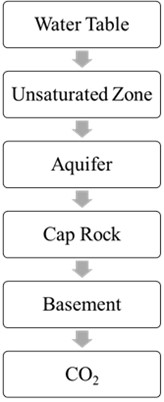
In an unconfined aquifer, there is no confining layer restricting the vertical movement of fluids. This lack of a confining layer means that there is little resistance to the upward migration of injected substances, such as CO2. When CO2 is introduced into the unconfined aquifer, its buoyancy causes it to tend to move upward within the geological formation. The buoyancy of CO2, combined with the absence of a confining layer, makes it prone to vertical migration, posing a risk of escape towards the surface (Fig. 3(a)).
To prevent the undesired upward movement of CO2 and secure its containment within the targeted aquifer, it is crucial to have a caprock or another form of confining layer. A caprock serves as an impermeable barrier above the aquifer, inhibiting the vertical migration of fluids, including CO2. By providing a sealing layer, the caprock helps trap the injected CO2 within the aquifer, preventing its escape and ensuring the success of carbon capture and storage (CCS) or other subsurface injection processes.
Fig. 2Potential leakage routes, modified from [4]
![Potential leakage routes, modified from [4]](https://static-01.extrica.com/articles/23889/23889-img2.jpg)
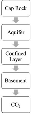
2.2. CO2 storage in confined aquifer
In a confined aquifer, there is a confining layer above the aquifer that prevents the CO2 from migrating upward. CO2 is injected into the aquifer, and it is trapped below the confining layer. (Fig. 3(b)). The pressure of the injected CO2 may increase over time, and this may cause the CO2 to migrate into adjacent rock formations. Therefore, monitoring and management of the CO2 storage is important to ensure its safety and effectiveness.
Fig. 3CO2 Sequestrations in an unconfined aquifer and confined aquifer
a) Unconfined aquifer
b) Confined aquifer
2.3. CO2 storage in depleted hydrocarbon reservoirs
In a depleted oil or gas reservoir, CO2 is injected into the formation through a well drilled into the rock. The CO2 mixes with the residual oil or gas and reduces its viscosity, making it easier to extract. The CO2 also displaces the oil or gas and occupies the pore space in the rock. The impermeable layers of rock surrounding the reservoir act as a cap, preventing the CO2 from escaping to the surface.
3. Risk associated with CO2 sequestration in saline aquifers
Saline aquifers are underground water-bearing formations that contain high concentrations of salt and are unsuitable for human consumption or irrigation. They are considered a promising option for CO2 storage because they have large storage capacity and are widely distributed. However, there are several specific risks associated with this type of storage, including:
3.1. Insufficient data on saline aquifers
Saline aquifers are typically not as well-studied as abandoned oil or gas fields, and therefore acquiring data to characterize these reservoirs can be costlier. In many cases, there may be limited or no existing data on the geology, fluid properties, and other parameters needed to build an accurate reservoir model. To obtain this information, exploration companies may need to conduct additional surveys and measurements, such as seismic surveys, well drilling, and geophysical logging. These methods can be expensive and time-consuming, particularly if the target reservoir is deep or located in a remote area.
Furthermore, saline aquifers may have different geological and hydrological properties than oil and gas reservoirs, requiring different approaches to reservoir characterization and modeling. For example, saline aquifers may be more porous and permeable than conventional oil and gas reservoirs, which can affect fluid flow and migration paths.
3.2. Cap rock integrity
In abandoned hydrocarbon fields, the existence of a seal is already demonstrated by the presence of the hydrocarbon reservoir itself. However, in the case of aquifers, it is not always obvious if there is a sealing layer that is preventing the water from escaping.
Analogies to hydrocarbon fields can be useful in identifying potential sealing layers, but they cannot always be relied upon to determine the presence or properties of a cap rock. In order to determine cap rock properties for an aquifer, it may be necessary to conduct tests and use modeling techniques to evaluate the sealing potential of the various layers present in the subsurface.
3.3. Geochemical issues
The chemical interactions between injected CO2 and rocks and the formation water can have significant consequences for the success of CO2 sequestration. The specific reactions that occur will depend on the unique geochemical conditions of the site, including the mineralogy and petrography of the reservoir and cap rocks. Geochemical experiments using physical samples of the rocks are the best way to predict these reactions accurately. However, it is important to note that some of these reactions can take a very long time to occur, making data collection and simulation challenging.
Some potential reactions that can occur include corrosion of the reservoir rock matrix, leading to the compaction or collapse of the formation and the development of cracks and new migration paths through the cap rock. Dissolution of primary minerals and precipitation of secondary minerals may also occur, leading to injection problems if safe pore fluid pressure is likely to be exceeded.
Other potential reactions include the dissolution of components of the cap rock by CO2/water mixtures, leading to its collapse or failure as a seal, dehydration of the cap rock by reaction with the dry injected CO2, leading to shrinkage and the creation of new pathways through it for CO2, and dissolution of CO2 into the pore fluid and transport out of the structure by natural or induced pore fluid flow.
3.4. Pore fluid pressure issues
The most common problems associated with pore fluid pressure are:
1. The fracturing of the cap rock, can occur when the pore fluid pressure in the reservoir exceeds the strength of the cap rock. This can lead to the creation of new fractures or the propagation of existing ones, which can potentially allow the CO2 to escape from the reservoir.
2. The opening up of pre-existing but previously closed migration paths, can occur when the increased pore fluid pressure in the reservoir causes the cap rock to fail along pre-existing weaknesses such as faults. This can create new pathways for the CO2 to migrate out of the reservoir and potentially reach the surface.
3. The breaching of the cap rock due to the high gas pressure in the CO2 accumulation, can occur when the gas pressure exceeds the capillary entry pressure of the cap rock. Capillary entry pressure is the minimum pressure required to force a fluid into a porous material against the forces of surface tension. If the gas pressure exceeds this pressure, the CO2 can pass through the cap rock and escape from the reservoir [10-12].
4. Method
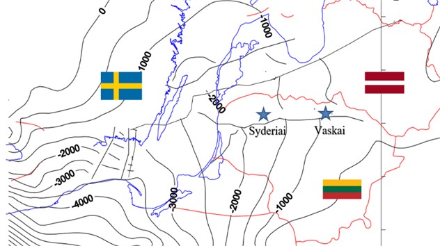
In Lithuania’s Baltic Basin, research is still in its early stages regarding the long-term fate of geological CO2 storage [7, 8]. This study focuses on the deep saline aquifers, Syderiai of the Baltic Basin (shown in Fig. 4) and aims to demonstrate the effect of Fault and fracture on CO2 injection. Lithuanian Basin has a number of deep saline aquifers and depleted hydrocarbon reservoirs in onshore and offshore settings. A detailed ranking of these subsurface storage sites has been analyzed and presented in [7, 8]. The focus of this paper is on the deep saline aquifer. The largest in terms of storage are two onshore deep saline aquifers Syderiai and Vaskai. In this study we focus on Syderiai aquifer only. High level geological models are built using mechanistic modelling approach whereby average properties are used to make a layer cake model. Geology of the region is represented using simple gaussian distribution. The models are then infused with high permeability faults and fractures to test various leakage scenarios based on the magnitude of fault and fracture permeability.
Fig. 4Location of saline aquifers in Lithuanian geological basin
The methodology employed in this study aimed to develop a mechanistic model of the Syderiai deep saline aquifer within the Lithuanian basin, which has been shows to have a significant representative storage volume [7]. The model was constructed based on key geological parameters, including average permeability, porosity, net-to-gross ratio (NTG), and aquifer thickness. The primary focus of this research was to address the issue of leakage in the deep saline aquifer resulting from the injection of carbon dioxide (CO2).
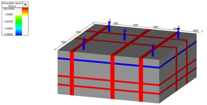
To investigate the relationship between CO2 leakage volume and fracture permeability, a box model was created. The box model comprised of a fracture network and a top seal layer, see Fig. 5. We assumed there was no CO2 present in the deep saline aquifer when we started simulation. Additionally, Python programming language and relevant libraries were utilized for the implementation of the model and the calculation of leakage volumes from fractures. Simulations are conducted using T-navigator simulation software [13].
Fig. 5a) Permeability distribution grid block for 1000 md fracture, b) soluble CO2 in water for 1000 md fracture after 100 year
a)
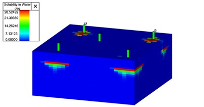
b)
5. Result
The results of our study indicate a clear dependence of CO2 leakage volume on fracture permeability. An initial observation reveals a positive correlation, as the leakage volume of CO2 tends to increase with higher levels of fracture permeability. This finding aligns with the expectation that greater permeability provides enhanced pathways for fluid movement, resulting in a higher potential for CO2 migration. As fracture permeability continues to increase, the sealing effects become more pronounced, leading to a subsequent decrease in CO2 leakage volume. Fig. 5, shows simulation results on a synthetic case where faults and fractures are present and CO2 is injected and it can be seen that CO2 migration is not fast enough to leak through the fracture network due to the distance between injection wells and the fractures present in the system.
6. Conclusions
This paper tests the leakage volumes using different fracture configurations and fracture permeability values. Optimal conditions for minimizing leakage were identified. Investigations were made for the temporal dynamics of CO2 leakage volumes. Analysis was carried out to look at factors such as cap rock degradation through geochemical reactions and pressure differentials, to understand how the leakage volume evolved over time.
References
-
David Reiner, Xi Liang, X. Sun, Yizhong Zhu, and Di Li, “Stakeholder attitudes towards carbon dioxide capture and storage technologies in China,” in International Climate Change Conference, pp. 29–31, May 2007.
-
J. T. Birkholzer, C. M. Oldenburg, and Q. Zhou, “CO2 migration and pressure evolution in deep saline aquifers,” International Journal of Greenhouse Gas Control, Vol. 40, pp. 203–220, Sep. 2015, https://doi.org/10.1016/j.ijggc.2015.03.022
-
N. Castelletto, G. Gambolati, and P. Teatini, “Geological CO2 sequestration in multi‐compartment reservoirs: Geomechanical challenges,” Journal of Geophysical Research: Solid Earth, Vol. 118, No. 5, pp. 2417–2428, May 2013, https://doi.org/10.1002/jgrb.50180
-
A. Zappone et al., “Fault sealing and caprock integrity for CO2 storage: an in situ injection experiment,” Solid Earth, Vol. 12, No. 2, pp. 319–343, Feb. 2021, https://doi.org/10.5194/se-12-319-2021
-
S. Bachu and J. J. Adams, “Sequestration of CO2 in geological media in response to climate change: capacity of deep saline aquifers to sequester CO2 in solution,” Energy Conversion and Management, Vol. 44, No. 20, pp. 3151–3175, Dec. 2003, https://doi.org/10.1016/s0196-8904(03)00101-8
-
“Global Status of CCS 2021 CCS Accelerating to Net Zero,” Global C.C.S. Institute Report, 2021.
-
S. Malik, P. Makauskas, V. Karaliūtė, M. Pal, and R. Sharma, “Assessing the geological storage potential of CO2 in Baltic basin: a case study of Lithuanian hydrocarbon and deep saline reservoirs,” in The 12th Trondheim Conference on CO2 Capture, Transport and Storage, Jan. 2023, https://doi.org/10.2139/ssrn.4493862
-
M. Pal, S. Malik, V. Karaliūtė, P. Makauskas, and R. Sharma, “Assessing the feasibility of carbon capture and storage potential in Lithuanian geological formations: a simulation-based assessment,” in 84th EAGE Annual Conference and Exhibition, Vol. 2023, No. 1, pp. 1–5, Jan. 2023, https://doi.org/10.3997/2214-4609.202310502
-
B. Metz, O. Davidson, H. C. de Coninck, M. Loos, and L. Meyer, IPCC Special Report on Carbon Dioxide Capture and Storage. Cambridge: Cambridge University Press, 2005.
-
M. Malo and K. Bédard, “Basin-scale assessment for CO2 storage prospectivity in the province of Québec, Canada,” in Energy Procedia, Vol. 23, pp. 487–494, Jan. 2012, https://doi.org/10.1016/j.egypro.2012.06.031
-
J. M. Nordbotten, M. A. Celia, and S. Bachu, “Injection and storage of CO2 in deep saline aquifers: analytical solution for CO2 plume evolution during injection,” Transport in Porous Media, Vol. 58, No. 3, pp. 339–360, Mar. 2005, https://doi.org/10.1007/s11242-004-0670-9
-
R. Span and W. Wagner, “A new equation of state for carbon dioxide covering the fluid region from the triple‐point temperature to 1100 K at pressures up to 800 MPa,” Journal of Physical and Chemical Reference Data, Vol. 25, No. 6, pp. 1509–1596, Nov. 1996, https://doi.org/10.1063/1.555991
-
“T-Navigator, Reservoir Simulation Software Version 21.3, Rock flow Dynamics,” 2022.
About this article

We acknowledge the essential role played by the RFML lab (Rock and Fluid Multiphysics Laboratory, IITR) in facilitating my research by providing access to crucial facilities and expertise. Additionally, we extend our sincere gratitude to KTU, Lithuania, for their unwavering support throughout this research, providing valuable insights and data critical to the success of this study. The author would like to thank Rock Flow Dynamics for providing academic licenses for T-navigator, which was used in conducting the simulation study.
The datasets generated during and/or analyzed during the current study are available from the corresponding author on reasonable request.
Shankar Lal carried out modelling, drafting and revisions, Shruti Malik, Pijus Makauskas, Vilte Karliute helped preparing of the data file used in simulation models, Ravi Sharma and Mayur Pal helped in drafting and reviewing of manuscript and guiding through development of the methodology.
The authors declare that they have no conflict of interest.
