High energy, high average power ytterbium lasers
Published July 2021
•
Copyright © IOP Publishing Ltd 2021
Pages 1-1 to 1-26
You need an eReader or compatible software to experience the benefits of the ePub3 file format.
Download complete PDF book, the ePub book or the Kindle book

Permissions
Abstract
Chapter 1 discusses the most recent achievements in terms of high energy, high average power laser systems, reporting the use of Ytterbium:YAG gain medium to generate picosecond pulses with kW of average power at kHz repetition rate for Joule energy per pulse. These performances combine the highest pulse energy and average power to date, and will enable scaling by orders of magnitude the brightness of secondary sources driven by high energy pulses.
1.1. Introduction
Since the invention of the laser, higher pulse energy, greater average power, and shorter pulse duration are constantly evolving frontiers that create new applications and even open entire new fields. The peak power of lasers has increased over the years at a rate that compares with the dramatic increase of the number of transistors in semiconductor chips (Moore's law), at present reaching 10 PW [1]. Impressive increases have also been achieved in pulse energy, with lasers now delivering nanosecond pulses of more than one megajoule [2]. Dramatic reductions in pulse durations have also been realized with laser pulses with hundreds of joules being produced in the femtosecond regime [1]. However, the average power of joule-level ultrashort pulse lasers has, until very recently, remained low. There are important applications in science and technology in which progress depends on the development of compact lasers capable of producing ultrashort laser pulses of high energy at high repetition rate. These applications include coherent and incoherent plasma-based sources of extreme ultraviolet, soft and hard x-rays photons, and the production of gamma rays by inverse Compton scattering. Also, high power, ultrashort pulse lasers operating at repetition rates at and above 1 kHz are required for the implementation of compact particle accelerators based on laser wakefield acceleration for fundamental research and applications. These and other applications motivate the development of high average power, short pulse lasers at institutions worldwide.
Figure 1.1 summarizes the current state-of-the-art of high energy, high average power, short pulse (<10 ps) lasers operating at wavelengths near 1 μm, which is, at present, the wavelength range that has produced the highest average powers. Different approaches, all of them enabled by pumping with laser diodes, have been investigated. The gain geometry has been in the form of slabs, thin disks, or thicker disks operating at cryogenic temperatures. Another approach uses the coherent combination of the output of fiber lasers. Most of these lasers are based on diode-pumping of Yb:YAG, a mature gain material that is readily available and that combines high heat conductivity, large stimulated emission cross section, and relatively broad bandwidth. Yb:YAG picosecond lasers have already reached a pulse energy of 1 J at a repetition rate of 1 kHz, and further increases in both the average power and the pulse energy are expected.

Figure 1.1. Summary of state-of-the-art diode-pumped Yb-doped lasers at λ ≈ 1 μm with high pulse energy (>10 mJ) and repetition rate of up to 10 kHz with pulses compressible to sub-10 ps duration. Each number identifies work listed in the reference section [3–26].
Download figure:
Standard image High-resolution imageIn this chapter we discuss the material properties of Yb:YAG in comparison with other Yb host materials, followed by a summary of its characteristics at cryogenic temperature relative to room temperature. This is followed by a discussion of the state-of-the-art high average power, high energy, thin disk lasers and cryogenic Yb:YAG lasers.
1.2. Yb-doped gain media
The advent of highly efficient, high power semiconductor laser diodes with narrow band emission which better matches the absorption of solid state laser materials than flash lamps has enabled important advances in high power lasers. It has resulted in greatly increased efficiency, larger average power, increased compactness, and reliability. However, a limitation of laser diodes as compared to traditional flash lamps is their relatively low peak power. This requires using gain media with long upper level lifetime that can efficiently store the pump energy. Numerous laser materials with adequate laser upper level lifetime for pumping with laser diodes have been investigated or are under development. The two rare earth ion dopants, neodymium and ytterbium, have so far dominated the development of high power lasers. They are well suited for diode pumping due to the inherent wavelength matching between their absorption bands and that of commercially available high power diodes. Nd+3 can be efficiently pumped by λ = 790–900 nm InGaAsP/GaAs or AlGaAs/GaAs laser diodes, and Yb+3 by λ = 900–980 nm InGaAs/GaAs laser diodes. Yet Yb3+ materials such as Yb:YAG have the advantage of having an upper level lifetime of ∼1 ms, which is over four times longer than similar Nd3+ materials like Nd:YAG, which has a lifetime of 230 μs. This allows for better pump energy usage, and therefore reduced cost. Furthermore, when pumped at λ = 942 nm Yb:YAG has an absorption bandwidth of 18 nm full width at half maximum (FWHM) [27], which is nearly an order of magnitude greater than the 2 nm absorption bandwidth of Nd:YAG at λ = 808 nm. This relaxes diode linewidth and center wavelength stability requirements.
Figure 1.2 shows the energy level diagrams for Nd3+ and Yb3+. In both materials lasing takes place at wavelengths around 1 μm in transitions between the 4F5/2 and 4I11/2 manifolds in Nd3+ and between the 2F5/2 and 2F7/2 manifolds in Yb3+. A first observation is the different value of the quantum defect between the two materials, i.e., the difference between pump and emission wavelengths. When expressed as the fraction of the lasing wavelength to the pump wavelength, Nd:YAG has a quantum defect of 24% when pumped at 808 nm, while Yb:YAG has a value of 9% when pumped at 942 nm. This is significant because the quantum defect is often the primary direct source of heating in the material. Therefore, minimizing the lasing to pump wavelength difference is key for high power laser operation, where thermal management is one of the major challenges. Yb3+ also has a simplified electronic energy level diagram that helps to avoid most parasitic effects such as energy transfer upconversion, excited state absorption, and cross-relaxation, which all occur in Nd-doped media because of the existence of higher energy levels [27]. The main de-excitation paths of these high energy levels are primarily non-radiative and contribute to further thermal loading of the system. These deleterious effects can also depopulate the laser upper level, therefore reducing the population inversion and the gain. Finally, an advantage for the development of ultrafast lasers is the broader laser line emission bandwidth of Yb-doped materials, that is about an order of magnitude broader than of Nd-doped materials, allowing for the generation of shorter transform limited laser pulses. This broader gain bandwidth combined with longer storage lifetime comes with the consequence of lower peak stimulated emission cross section and the corresponding higher saturation fluence. Additionally, the small quantum defect results in a non-negligible thermal population on the lower laser level which increases threshold pumping requirements. However, as we discuss below, these complications are ameliorated at cryogenic operating temperatures. Overall, the Yb3+ ion has emerged over Nd+3 as a prime candidate for high repetition rate, high power, ultrafast laser development.
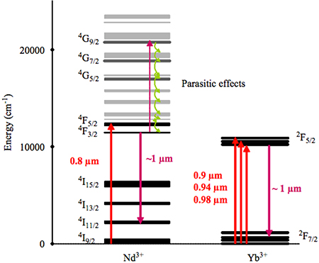
Figure 1.2. The relevant energy levels of Nd3+ and Yb3+ gain media with typical pump and lasing transitions, as well as parasitic effects. Reprinted from Chenais et al [27], Copyright 2006, with permission from Elsevier.
Download figure:
Standard image High-resolution imageNumerous Yb-doped gain media with different host materials exist that exhibit many of
the spectroscopic properties discussed above. These materials have long upper level
lifetimes,  , and small quantum defects, but differences
in material properties make some more suitable than others for high power operation.
These materials include Yb:YAG, Yb:KYW, Yb:KGW, Yb:YLF, and Yb:CaF2. Some of
their spectroscopic and mechanical properties are listed in table 1.1.
, and small quantum defects, but differences
in material properties make some more suitable than others for high power operation.
These materials include Yb:YAG, Yb:KYW, Yb:KGW, Yb:YLF, and Yb:CaF2. Some of
their spectroscopic and mechanical properties are listed in table 1.1.
Table 1.1. Spectroscopic and mechanical properties of various Yb-doped materials. From S Chenais et al [27]. Other values have also been reported [28–32].
| Crystal host |
 (nm) (nm) |
 (nm) (nm) |
∆λ (nm) |
 (10−20
cm2) (10−20
cm2) |
 (ms) (ms) |
κ (W m−1 K−1) (undoped) |
|---|---|---|---|---|---|---|
| YAG | 1030 | 942 | 9 | 2.1 | 0.95 | 11 |
| KYW | 1025 | 981 | 24 | 3 | 0.3 | 3.3 |
| KGW | 1023 | 981 | 20 | 2.8 | 0.3 | 3.3 |
| YLF | 1030 | 959 | 14 | 0.81 | 2.21 | 4.3 |
| CaF2 | 1049 | 980 | 70 | 0.25 | 2.4 | 9.7 |
Several of these materials have been explored as options for high power lasers [33–36]. Hosts such as YLF and CaF2 are attractive due to their broad emission bandwidth, Δλ, and good thermal conductivities, κ, and could constitute alternatives for high energy femtosecond lasers. These materials have found use in short pulse high power oscillators [37] and low energy amplifiers [3, 13, 38]. Yb:CaF2 has also been used in diode-pumped high energy amplifiers [39, 40] to generate laser pulses of up to 54 J at repetition rates of less than 1 Hz, compressible to ∼100 fs. Yet, its low stimulated emission cross section, σe , means it has a low gain, and a high saturation fluence. The saturation fluence of Yb:CaF2 can exceed 100 J cm−2, which is well above the damage threshold of optical coatings and even of the host material itself. This is a significant limitation for its use in the implementation of high average power, high energy amplifiers, where it is necessary to operate above the saturation fluence for efficient energy extraction. In the case of KYW and KGW, their low thermal conductivities have limited their use to mode-locked oscillators [41, 42] and low energy amplifiers [33, 34]. Of the available host materials, Yb:YAG, which has relatively high thermal conductivity and comparatively low saturation fluence, has emerged as the most utilized material for high energy, high repetition rate picosecond laser operation. Yttrium aluminum garnet (Y3Al5O12), or YAG, has been a popular host material for decades due to its attractive spectroscopic, mechanical, and thermal properties. YAG has a body-center cubic lattice that makes it optically isotropic. However, thermal stress can still cause depolarization. YAG also has a higher fracture strength than most laser materials and is well suited to accept substitution of trivalent rare earth ions. Furthermore, since YAG has been studied as a laser host since the mid-1960s [43] and has found wide use with Nd3+ and Yb3+ dopants, the fabrication of high quality single crystal and ceramic YAG is mature, making large aperture YAG-based gain media commercially available. In recent decades, Yb:YAG has found wide use in high power picosecond chirped pulse amplification (CPA) lasers using a number of different designs including water-cooled thin disks [14–16], slabs [19, 44], and thicker disks or slabs operating at cryogenic temperatures [23–26]. Cryogenic Yb:YAG is particularly well suited for high pulse energy operation at high repetition rates.
1.2.1. Yb:YAG at cryogenic temperatures
The thermo-optical and mechanical properties of Yb:YAG as a gain medium for high power lasers improve greatly at cryogenic temperature [28, 45–47]. From table 1.1, we see that at room temperature YAG has a thermal conductivity of 11 W m−1 K−1, which is better than many of the other host materials listed. However, it is still significantly worse than other host materials like sapphire used in Ti:Sapphire lasers, which has a thermal conductivity of 33 W m−1 K−1 at room temperature. Nevertheless, when cooled to cryogenic temperatures, the thermal conductivity of undoped YAG increases by nearly a factor of 9 with respect to room temperature. While this advantage is reduced when moderate levels of doping are introduced, a significant improvement of 3–5 times still remains [28]. In addition, as shown in table 1.2, the thermal expansion coefficient as well as the thermo-optic coefficient improve at cryogenic temperatures. The former is reduced by a factor of 4 as the temperature decreases from 300 K to 77 K, while the thermo-optics coefficient decreases by a factor of 7. In addition, the emission spectrum of Yb:YAG is significantly narrower at 77 K, which leads to an increase of the stimulated emission cross section and the corresponding decrease in the saturation fluence to below 2 J cm−2 [46]. This decrease in saturation fluence allows for efficient energy extraction without optical damage to the coatings and bulk materials. The associated increase in gain also allows for efficient energy extraction in a low number of passes through the gain media, which helps to avoid high nonlinear phase accumulation. On the other hand, the narrower spectral bandwidth limits the shortest pulsewidth that can in practice be obtained to a few picoseconds. Therefore, several high energy cryo-cooled Yb:YAG laser system designs that suffer bandwidth narrowing in the amplifier chains have used hybrid approaches that combine either different cryogenically-cooled Yb-doped amplifier materials [18] or cryogenically-cooled power amplifiers with a room temperature first amplification stage where most of the gain takes place [23, 48].
Table 1.2. Optical and mechanical properties of Yb:YAG at room temperature and at liquid nitrogen temperature. The column to the right quantifies the change. Values according to references [28, 45–47].
| Yb:YAG properties at room and cryogenic temperature | 300 K | 77 K | Factor |
|---|---|---|---|
| Thermal conductivity (W m−1 K−1) | 10 | 90 | × 9 |
| Thermo-optic coefficient (10−6/K) | 7.8 | 0.9 | × 1/7 |
| Expansion coefficient (10−6/K) | 6.14 | 1.95 | × 1/4 |
| Saturation fluence (J cm−2) | 9.2 | 1.7 | × 1/7 |
A disadvantage of Yb:YAG's simple two manifold electronic structure and low quantum defect is that the lower laser level is thermally populated at room temperature. From Maxwell–Boltzmann statistics, the fraction of ions in the lower laser level has a population of 5.3% at 300 K due to thermal excitation from the ground state. This makes room temperature Yb:YAG a quasi-three level laser (figure 1.3(left)). Since there is an overlap between the absorption and emission bands, this leads to significant re-absorption and to a reduction of the effective emission bandwidth [28]. Therefore, there is a minimum amount of pump energy required for the system to reach transparency, and a corresponding reduction in the laser efficiency. This changes greatly when Yb:YAG is cooled to cryogenic temperatures, i.e., at ~77 K, liquid nitrogen temperature. At this temperature the fraction of ions in the lower laser level is reduced to 10−5, making Yb:YAG a four level laser system (figure 1.3(right)), in which a population inversion and gain start to build up at low pump energy.
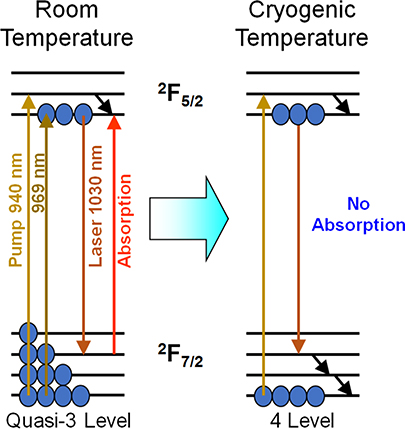
Figure 1.3. Population of the laser lower level in Yb:YAG at room and cryogenic temperature. The laser material changes from a quasi-three level system at room temperature (left) into a four level system at cryogenic temperature (right).
Download figure:
Standard image High-resolution image1.3. Thin disk lasers
The thin disk laser concept for the implementation of high average power diode-pumped solid state lasers, which dates back to 1994 [49], is illustrated in figure 1.4. The approach consists in the use of an active medium in the shape of a thin disk, typically 100–300 μm thick, that is cooled through one of the flat faces which is bonded to a water-cooled heat sink. The cooled face is coated with a dielectric multilayer stack that is highly reflective for both the pump and the laser wavelengths, while the opposite side of the disk is coated with an anti-reflection coating at both wavelengths. This geometry, which acts as a mirror with gain, is known as an 'active mirror', which can be used in reflection in an oscillator or amplifier. As the pump spot size is typically much larger than the disk thickness, one-dimensional heat flow results in which the temperature gradients are mainly coaxial to the disk and the laser beam. Therefore, the thermal lens effect can be greatly reduced with respect to an edge-cooled rod geometry, allowing for power scaling. Also, the large surface-to-volume ratio allows for efficient heat dissipation from the active medium into the heat sink, enabling operation at very high power densities.
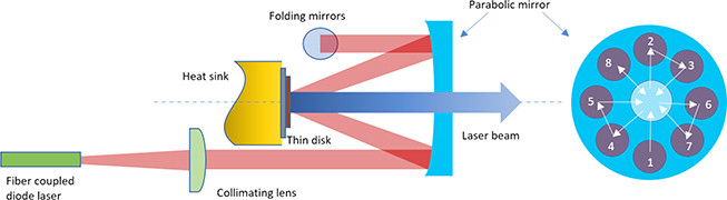
Figure 1.4. (a) Schematic illustration of the thin disk configuration for 16 pump passes. © 2007 IEEE. Reprinted, with permission, from Giesen et al [50].
Download figure:
Standard image High-resolution imageBecause of the small crystal thickness only a small fraction of the pump power is absorbed, requiring multiple passes of the seed beam through the gain medium. Figure 1.4 shows a typical arrangement to increase the number of pump beam passes through the crystal employing a parabolic mirror and a set of prism retro-reflectors. After each pass, the unabsorbed portion of the pump beam is collimated again by the other side of the parabolic mirror that focuses it onto the disk. This re-imaging is repeated until all the positions of the parabolic mirror are covered, the point at which the pump beam can be redirected back to the source, thereby doubling the number of passes through the thin disk. This provides a platform for efficient pumping in which more than 90% of the pump power is absorbed in the disk. The small thickness also results in a small single pass gain that for efficient amplification requires multiples passes either in a resonator of a multi-pass amplifier configuration (figure 1.5(a)), or in a regenerative amplifier (figure 1.5(b)).
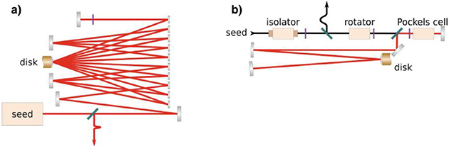
Figure 1.5. Schematic representation of (a) multi-pass amplifier, and (b) thin disk regenerative amplifier. From Saraceno et al [51] (2019). With permission of Springer.
Download figure:
Standard image High-resolution image1.3.1. High energy thin disk regenerative amplifiers
The thin disk configuration has been used with Yb:YAG to create high average power regenerative amplifiers with output pulse energy of up to 100–200 mJ at repetition rates of 5–10 kHz [16]. This 1 kW average power CPA regenerative amplifier system used the architecture illustrated in figure 1.6(a) [16]. Pulses of 1.3 μJ energy from a Kerr-mode-locked thin disk oscillator are stretched to 1.5 ns duration in a grating stretcher. The stretched pulses are amplified to 1–2 mJ in a first thin disk regenerative amplifier. A following main amplifier is built around two diode-pumped water-cooled Yb:YAG thin disk amplifier heads that constitute the gain media in the ring-type resonator illustrated in figure 1.6(b). CW pump diodes operating at wavelengths of 969 nm are used to pump 6.8 mm spots into the 200 μm thick thin disks. The pump diodes are stabilized by volume Bragg gratings to enable direct pumping of the upper laser level via the narrow bandwidth zero phonon line. The resonator mode is symmetric with respect to the position of the two laser disks, ensuring similar mode size in both crystals. The first regenerative amplifier is used to increase the seed pulse energy to avoid chaotic behavior and achieve stable operation of the main amplifier.
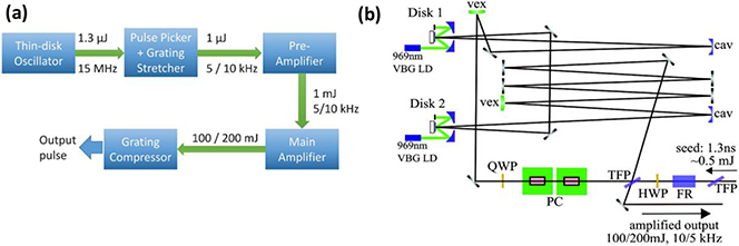
Figure 1.6. (a) Architecture of a kW average power 100–200 mJ thin disk regenerative amplifier. (b) Optical setup of the regenerative amplifier. QCW, quarter-wave plate; HWP, half-wave plate; FR, Faraday rotator; PC, Pockels cell; TFP, thin-film polarizer. VEX denotes a 10 m radius of curvature convex mirror; and CAV is a 15 m radius of curvature concave mirror. Reprinted with permission from Nubbemeyer et al [16] © The Optical Society.
Download figure:
Standard image High-resolution imageAs shown in figures 1.7(a) and (b), this system produces average powers exceeding 1 kW with the 100–200 mJ output pulse energies mentioned above. The spectral bandwidth of the pulses seeding the pre-amplifier is 3.5 nm and is reduced to 1.5 nm by gain narrowing in the two subsequent amplifier stages (figure 1.7(b)). The pulses were compressed to 1.08 ps using an efficient dielectric grating compressor. Another thin disk regenerative amplifier implementation has produced uncompressed pulses of slightly higher energy, 300 mJ, at 100 Hz repetition rate, that were subsequently compressed to 1.8 ps FWHM pulses of >240 mJ energy [52].

Figure 1.7. (a) Output power of thin disk regenerative amplifiers at 5 kHz repletion rate. (b) Output power at 10 kHz repetition rate achieved over several minutes. The insets show the measured output beam profiles for each repetition rate. (c) Spectra at the output of each of the stages of the regenerative amplifier depicted in figure 1.6: stretched seed pulse (blue dotted line), 1 mJ pre-amplifier output (red dashed line), and output of the main amplifier (black solid line). Reprinted with permission from Nubbemeyer et al [16] © The Optical Society.
Download figure:
Standard image High-resolution image1.3.2. Thin disk multi-pass amplifiers
Thin Yb:YAG disks have also been used to implement high average power, multi-pass amplifiers which provide a platform to further increase the pulse energy. Outputs with compressed pulses of up to 720 mJ at 1 kHz repetition rate have been reported [20]. The laser system that produced these pulses is schematically illustrated in figure 1.8. It combines a commercially available regenerative amplifier that is based on a ring configuration, figure 1.8(b), with a multi-pass amplifier, both pumped by λ = 940 nm laser diodes as shown in figure 1.8(c).

Figure 1.8. Thin disk laser system producing 720 mJ compressed pulses at 1 kHz repetition rate based on a thin disk regenerative amplifier followed by a multi-pass amplifier that uses four thin disks' amplifier heads. TFP, thin-film polarizer; HWP, half-wave plate; BBO PC, BBO-based Pockels cell. Reprinted with permission from Herkommer et al [20] © The Optical Society.
Download figure:
Standard image High-resolution imageThe multi-pass amplifier is arranged in two stages, each made of two amplifier heads. A total average accumulated pump power of >9 kW is absorbed in the four water-cooled amplifier heads. The thermal lens at the operation point is compensated to obtain near-collimated propagation. The approach allows guiding of the seed beam over the thin disks multiple times with adjustable beam diameters using mirrors which are selected depending on the evolving beam size and divergence. Figure 1.9 shows the measured pulse output energy of each amplification stage as a function of seed pulse energy, maintaining constant pump power. In the first stage of this multi-pass amplifier, 240 mJ pulses from the regenerative pre-amplifier are amplified in two laser heads to 550 mJ in seven passes. In the second stage, the pulse energy is further increased to 800 mJ by four additional disk reflections. The pulses exiting the multi-pass amplifier are compressed into 720 mJ pulses of 0.92 ps duration in a dielectric grating compressor. The M2 at the output of the amplifier was measured to be 1.89/2.32 in the major/minor axis.
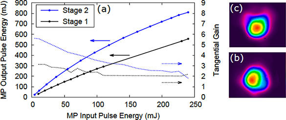
Figure 1.9. (a) Output pulse energy amplification characteristics of the two stages of the thin disk multi-pass amplifier of figure 1.8 as a function of seed pulse energy. The pump power is kept constant. (b) and (c) show the beam profiles after stage 1 and 2, respectively. Reprinted with permission from Herkommer et al [20] © The Optical Society.
Download figure:
Standard image High-resolution image1.4. Cryogenically-cooled Yb:YAG amplifiers
A different approach for the development of high energy, high average power amplifiers takes advantage of the improved thermo-optical and laser properties of Yb:YAG at cryogenic temperatures. The design architecture and performance of a compact λ = 1.03 μm CPA laser developed at Colorado State University based on cryogenically-cooled active mirror Yb:YAG amplifiers that produces pulses of up to 1.5 J at a repetition rate of 500 Hz is described below. The output pulses are compressed in vacuum to <5 ps in a dielectric grating compressor, yielding pulse energies of up to 1 J. A more recent implementation has produced 1.1 J picosecond pulses at 1 kHz repetition rate [26].
The approach relies on cryogenically-cooled Yb:YAG active mirrors. Although in these amplifiers the thickness of the gain medium (a few millimeters) is significantly larger than in the thin disk lasers, they share some of the same advantages. The geometry is still sufficiently thin to develop mostly longitudinal thermal gradients, reducing thermal lensing as compared to radially-cooled gain geometries. It also limits the maximum temperature difference within the gain region while its moderate diameter-to-length ratio reduces amplified spontaneous emission (ASE) depletion of the amplifier storage energy [53]. The improved thermal parameters at cryogenic temperatures compensate for the larger thickness of this geometry. Compared with thin disk lasers, the increased absorption reduces the number of passes necessary to efficiently absorb the pump, simplifying the design.
A block diagram showing the layout of the 500 Hz repetition rate, 1 J, picosecond laser system is shown in figure 1.10(a). The laser front-end is composed of a semiconductor saturable absorber mirror (SESAM) mode-locked Yb:KYW oscillator, a grating pulse stretcher, and a room temperature Yb:YAG regenerative amplifier. Since Yb:KYW is well suited to pumping by λ = 980 nm laser diodes, the crystal is pumped by a 30 W laser diode operating at that wavelength coupled to a 200 μm core fiber. The femtosecond pulses produced at 55 MHz repetition rate by the Yb:KYW oscillator are stretched by a 1740 line/mm grating to ~270 ps duration. The first stage of amplification is a room temperature Yb:YAG regenerative amplifier. This amplifier has the highest gain of any in the system, approximately 106, and is therefore where pulses suffer the most gain narrowing. Therefore, the choice of room temperature operation allows for a broader bandwidth [46]. Because of the mismatch between the center wavelength and the bandwidth of room temperature and cryogenic Yb:YAG, the stretcher is adjusted to select a spectral bandwidth that matches the region of peak gain in the subsequent cryogenic amplifiers while striking for a compromise between maximum pulse energy and broad spectral bandwidth at the exit of the final amplifier. Pulses leaving the grating stretcher seed the regenerative amplifier cavity via a thin-film polarizer (TFP). The active medium is a 0.5 mm thick, 10%-at. doped Yb:YAG active mirror soldered to a water-cooled copper heat sink. The Yb:YAG disk is pumped by ~200 W pulses of 200 μs duration from a fiber-coupled λ = 940 nm semiconductor laser diode. The stretched pulses suffer gain narrowing during amplification, and their pulse duration becomes 270 ps. These pulses can be compressed to ~2 ps durations, but their bandwidth is reduced when the wavelength is tuned to match the peak gain of the subsequent cryogenic amplifiers. The millijoule-level pulses are first amplified to about 100 mJ in a cryo-cooled pre-amplifier, and finally to the Joule level in the main multi-pass amplifier.
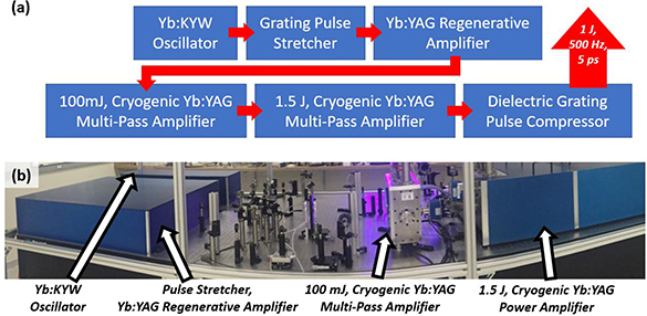
Figure 1.10. (a) Diagram of the laser system based on a high power, cryogenically-cooled Yb:YAG amplifier. The output of a diode-pumped, mode-locked bulk Yb:KYW oscillator is stretched by a grating stretcher and amplified to the millijoule level by a room temperature Yb:YAG regenerative amplifier. These seed pulses are subsequently amplified by a chain of two high power cryogenic amplifiers, and are compressed in vacuum by a dielectric grating pair. (b) Panoramic photograph of the high energy, high average power laser. Reproduced with permission from Reagan et al [54] © Cambridge University Press.
Download figure:
Standard image High-resolution image1.4.1. 100 mJ pre-amplifier
The layout of the 100 mJ-level amplifier is shown in figure 1.11(a). A 5 mm thick, 2%-at. Yb:YAG active mirror is mounted on a cryogenic cooling manifold enclosed in a vacuum chamber. The highly reflective face of the active mirror is cooled by flowing cryogenic liquid at 77 K [23]. The Yb:YAG active mirror is pumped by λ = 940 nm, 500 μs duration pulses produced by two 400 W peak power fiber-coupled laser diode modules. A pump spot diameter of ~3.5 mm was used, and the pump radiation is absorbed in a single pass (one reflection).

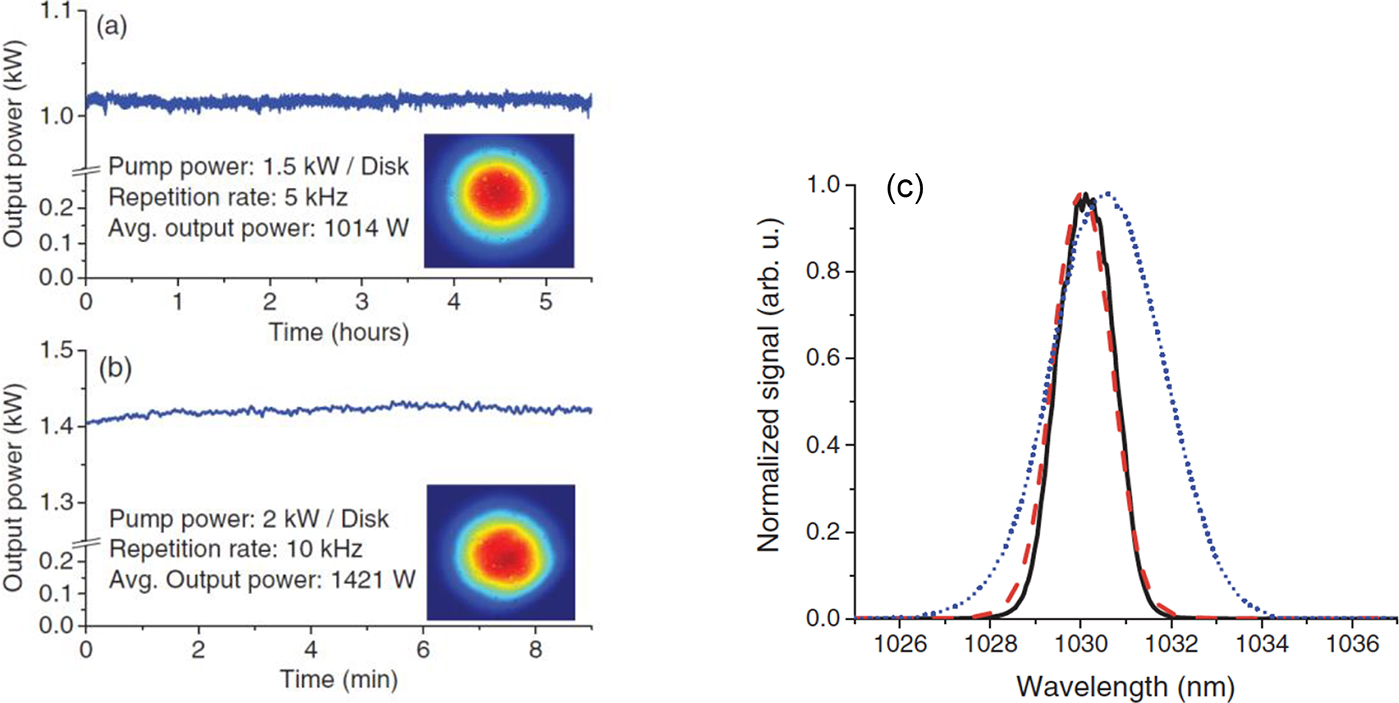
Figure 1.11. (a) Schematic layout of a 100 mJ, 500 Hz cryogenic amplifier. (b) Measured pulse energy at 500 Hz repetition rate as a function of total pump pulse energy. (c) Spectrum of the amplified pulses showing a bandwidth of 0.43 nm FWHM. (d) Autocorrelation of the compressed 100 mJ pulses at 500 Hz repetition rate. The sech2 fit shown corresponds to a pulse duration of 3.9 ps FWHM. Reproduced with permission from Reagan et al [54] © Cambridge University Press.
Download figure:
Standard image High-resolution imageThe seed pulses from the laser front-end make four passes through the amplifier. Figure 1.11(b) shows the measured pulse energy exiting the amplifier as a function of pump energy at 500 Hz repetition rate. As can be seen from this plot, an amplified pulse energy of 100 mJ (50 W average power) is obtained when pumped with 360 mJ at 500 Hz repetition rate. These pulses have a bandwidth of 0.43 nm FWHM (figure 1.11(c)) and were compressed to 3.8 ps FWHM duration as shown by the SHG autocorrelation of figure 1.11(d).
1.4.2. High repetition rate, 1.5 J amplifier
The Joule-level amplifier is shown in figure 1.12(a). Two Yb:YAG active mirrors are mounted on a single cryogenic cooling head. The active mirrors are composites consisting of a 30 mm × 30 mm × 2 mm thick 3%-at. Yb:YAG crystal optically bonded on the four lateral faces to an absorbing Cr4+:YAG cladding to reduce feedback of transversely emitted ASE and avoid parasitic oscillations. The front face of the assembly is bonded to an undoped YAG cap to further reduce ASE and to add mechanical stability. As shown in figure 1.12(a), each active mirror is pumped by pulses of 500 μs duration from a λ = 940 nm 6 kW laser diode stack. The pump beam diameter is ≈16 mm, and is double-passed to achieve >95% absorption. Seed pulses are injected into the amplifier through a TFP and are directed to pass through each active mirror twice. After double-passing a quarter-wave plate, the seed pulses pass back through the amplifier along the same path, achieving a total of four passes through each active mirror before being ejected from the amplifier by reflecting off the TFP. The amplifier occupies a table area of just over 0.5 m2.

Figure 1.12. (a) Layout of the high repetition rate, 1.5 J amplifier. (b) Photo of the enclosed amplifier, which occupies a table space of just over 1 m × 0.5 m. TFP, thin-film polarizer; λ/4, quarter-wave plate; P, periscope; 6 kW laser diode stacks. Reproduced with permission from Reagan et al [54] © Cambridge University Press.
Download figure:
Standard image High-resolution imageFigure 1.13 shows the performance characteristics of this amplifier operating at 500 Hz repetition rate. The laser output pulse energy as a function of total pump energy is displayed in figure 1.13(a). An output energy of 1.5 J (750 W average power) is obtained with an optical-to-optical efficiency of 37%. Figure 1.13(b) shows the measured output pulse energy stability over 30 min of continuous operation at 500 Hz repetition rate. A mean pulse energy of 1.4 J was obtained with an RMS deviation of 0.75%. Figure 1.13(c) shows a measured M2 parameter of ∼1.3 on both axes. The good beam quality in the far field is illustrated in figure 1.13(d). The pulses were compressed with about 70% efficiency by a pair of 1740 mm−1 dielectric diffraction gratings. The resulting pulses had an energy of 1 J and a duration of ~5 ps at 500 Hz repetition rate, generating an average power of 0.5 kW.

Figure 1.13. (a) Measured pulse energy exiting the main amplifier at 500 Hz repetition rate as a function of combined pump energy. (b) Amplified pulse energy over 30 min of continuous operation at 500 Hz repetition rate. A mean energy of 1.4 J was measured with an RMS fluctuation of 0.75%. (c) M2 measurement in two orthogonal directions of the amplified output producing 1.4 J at 500 Hz repetition rate. (d) Far-field beam image of the full power output. Reproduced with permission from Reagan et al [54] © Cambridge University Press.
Download figure:
Standard image High-resolution image1.4.3. 1.1 J, 1 kHz repetition laser picosecond Yb:YAG laser
A different version of this system resulted in the first demonstration of a picosecond laser emitting >1 J pulses at 1 kHz repetition rate [26]. This cryogenically-cooled system generates pulses with >1.2 J energy at a repetition rate of 1 kHz, corresponding to an average power of 1.26 kW. After compression with high efficiency dielectric gratings, 1.1 J pulses with a duration of 4.5 ps were generated with good beam quality and high shot-to-shot stability. A schematic of this kW average power CPA picosecond laser system is illustrated in figure 1.14. It consists of a room temperature front-end that generates 2 mJ seed pulses followed by two cryogenic amplification stages and a vacuum dielectric grating compressor.
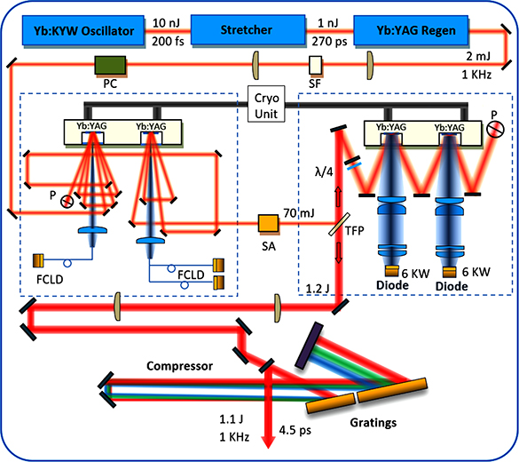
Figure 1.14. Schematic of the diode-pumped high energy CPA laser system. Regen, regenerative amplifier; SF, spatial filter; PC, Pockels cells; FCLD, fiber-coupled laser diodes; SA, serrated aperture; TFP, thin-film polarizer; P, periscope. Reprinted with permission from Wang et al [26] © The Optical Society.
Download figure:
Standard image High-resolution imageDiffering from the 500 Hz system [23], the room temperature, thin disk regenerative Yb:YAG amplifier is pumped at its zero phonon line by 500 μs pulses from a 969 nm wavelength 60 W fiber-coupled laser diode. An 8-pass pump geometry forms a well-overlapped pump area of 1 mm diameter with a pump absorption of over 95%. A plano-concave cavity allows for four passes through the gain medium per round trip. The pre-amplifier consists of two active mirrors based on 5 mm thick 2%-at. Yb:YAG crystals mounted into a single evacuated chamber where their back surfaces are cooled by flowing liquid nitrogen. The number of active mirrors in this pre-amp was increased to two to better distribute the thermal load and to allow for a longer effective gain medium. A total of seven passes achieves the desired amplification to 100 mJ pulse energy at 1 kHz repetition rate. The first of the two active mirrors is pumped by imaging the output of a 400 W, λ = 940 nm, fiber-coupled diode laser into a 4 mm diameter spot. The laser pulses are amplified in five passes through the first crystal and are subsequently further amplified in two passes through the second active mirror that is pumped into a similar spot by two 400 W fiber-coupled laser diodes. For both crystals, the pump pulse duration is set at 450 μs. The ~100 mJ pulses are passed through an 8 mm diameter serrated aperture (SA) to achieve a nearly flat-top beam profile and pass through a Faraday rotator before injection into the final dual crystal cryogenic amplifier. Each crystal in this final amplifier stage is pumped at λ = 940 nm by a 6 kW diode array. The pump diodes generate 380 μs duration pulses at 1 kHz that are shaped to form nearly flat-top 16-mm-diameter pump profiles onto each active mirror. The temperature at the center of the pump region was measured to remain below 130 K (figure 1.15) using a spectroscopic technique [55]. After the seed pulses pass twice through each of the two active mirrors, a periscope is used to spatially rotate the beam 90 degrees and change its height. The beam is sent back to the two active mirrors for the third and fourth pass. After the first four passes a quarter-wave plate combined with a 0-degree high reflector (HR) mirror rotates the polarization 90 degrees, sending the beam back through the same path to the TFP to exit the amplifier.
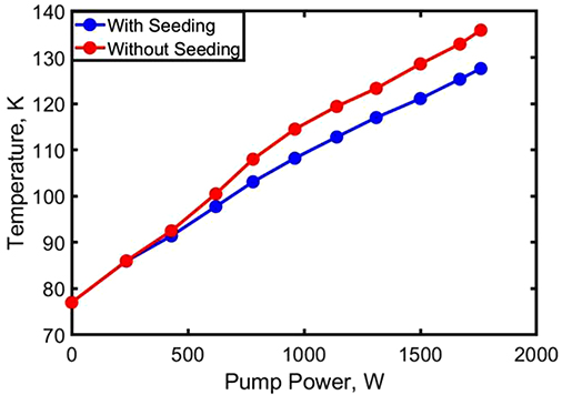
Figure 1.15. Measured temperature of one Yb:YAG active mirror in the final amplifier at the center of the pump with and without seeding vs. pump power. Reprinted with permission from Wang et al [26] © The Optical Society.
Download figure:
Standard image High-resolution imageFigure 1.16 shows the measured output pulse energy as a function of the final amplifier total pump energy at 1 kHz repetition rate. A maximum 1.26 J pulse energy (1.26 kW average power) was obtained with a total pump pulse energy of 3.5 J. The optical-to-optical conversion efficiency is ~36%. The pulse-to-pulse energy stability is characterized by a standard deviation of 0.6%. As also shown by the inset in figure 1.16, the 1.26 kW average power output beam has a uniform flat-top profile. The beam is characterized by a measured M2 = 1.32 and 1.39 on the horizontal and vertical directions, respectively (figure 1.17).
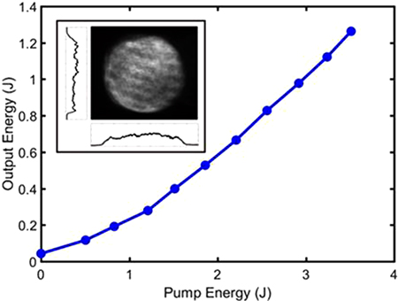
Figure 1.16. Measured laser pulse energy exiting the final amplifier as a function of total pump energy at 1 kHz repetition rate. A maximum energy of 1.26 J was obtained with a total pump energy of 3.5 J incident on the Yb:YAG active mirror. The inset shows the beam profile at 1 kHz, 1.26 kW average power. Reprinted with permission from Wang et al [26] © The Optical Society.
Download figure:
Standard image High-resolution image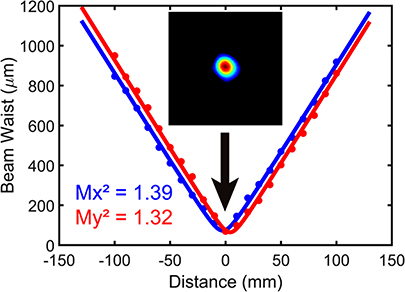
Figure 1.17. M2 measurement of the 1.2 J, 1 kHz repetition rate output beam. The inset image shows the far-field beam profile at focus. Reprinted with permission from Wang et al [26] © The Optical Society.
Download figure:
Standard image High-resolution imageFigure 1.18(a) shows the measured spectra before the pre-amplifier and after the main amplifier. A 0.35 nm FWHM bandwidth is obtained at the output of the final amplifier stage, showing a minimal amount of gain narrowing, which supports a transform limited pulse duration of 3.9 ps (sech2). Following amplification the beam is magnified to a diameter of ~40 mm and pulses are compressed with ~90% efficiency as shown by the SHG autocorrelator sech2 fit in figure 1.18(b) corresponding to a pulse duration of 4.48 ps FWHM. The demonstrated 1.2 kW average power amplifier chain also provides the opportunity to generate nanosecond lasers pulses by substituting the short pulse laser front-end with one generating seed pulses of nanosecond duration.

Figure 1.18. (a) Measured spectra at the input of the pre-amplifier (red) and the output of the final amplifier (blue). The pulses have an amplified bandwidth of 0.35 nm FWHM. (b) Second-harmonic autocorrelation after pulse compression. The solid trace is the sech2 fit with a width corresponding to a pulse duration of 4.48 ps. Reprinted with permission from Wang et al [26] © The Optical Society.
Download figure:
Standard image High-resolution image1.4.4. Frequency-doubled 1 J Yb:YAG laser with 1 kW average power
The output of λ = 1.030 μm Yb:YAG lasers can be efficiently frequency-doubled to drive high pulse energy femtosecond sources based on Ti:Sapphire or optical parametric chirped pulse amplifiers (OPCPA) at kHz repetition rates. Most of the progress achieved in the development of high average power green lasers based on Yb:YAG has been limited to the generation of μJ to mJ-level pulses at repetition rates ranging from hundreds of kHz to MHz [56, 57]. For example, 370 W average power at λ = 515 nm was achieved by the generation of 7 μJ pulses at 50 MHz repetition rate [56]. An average power of 1.4 kW at the same wavelength was achieved with 4.8 mJ pulses at 300 kHz repetition rate [57]. In comparison, the repetition rate and average power of lasers generating Joule-level green pulses has remained considerably lower until recently. SHG in the DIPOLE laser based on a cryogenically-cooled Yb:YAG laser has produced 5.6 J pulses at 10 Hz repetition rate, an average power of 56 W [58]. SHG in yttrium calcium oxyborate (YCOB) of pulses from the Yb:S-FAP Mercury laser produced 31.7 J at 10 Hz repetition rate (317 W average power) [59]. A 1 kHz cryogenically-cooled Yb:YAG laser similar to that described above has been frequency-doubled in LBO to generate 1 J green pulses and 1 kW average power [60].
This frequency-doubled Yb:YAG laser is schematically illustrated in figure 1.19. Infrared laser pulses of 1.2 J energy are produced with 1.2 kW average power and are frequency-doubled in two LBO crystals. Temporally square pulses were generated to maintain the intensity impinging into the doubling crystals at the optimum value for frequency doubling. Because the temporal profile of the pulses injected into the amplifier chain is re-shaped by gain saturation as they are amplified to the Joule level, the seed pulses are generated by an arbitrary-waveform laser, which is programmable to generate a square pulse shape at the end of the amplifier chain. A schematic of the setup used to generate seed pulses of arbitrary shape is shown in the upper part of figure 1.19. The seed laser comprises a 2 W peak power λ = 1030 nm diode laser, an electro-optic modulator (EOM), an arbitrary-waveform generator (AWG), and a processing unit. The seed semiconductor laser is temperature tuned to operate at the wavelength corresponding to high gain in the following chain of Yb:YAG cryogenic amplifiers. A photodiode is placed at the output of the amplifier chain to monitor the final pulse shape and provide the feedback necessary to adjust the input signal of the programmable AWG. The adjusted signal is then again applied to the EOM. This feedback process repeats until the desired pulse shape is achieved at the output of the amplifier chain. Figure 1.20(a) shows the measured temporal profile of the amplified 1.2 J square pulse, along with that corresponding to the shaped seed pulse before the cryogenically-cooled regenerative amplifier (figure 1.20(b)). While only the square pulse shape relevant to SHG is presented here, other pulse shapes can be generated with the same setup for other applications.
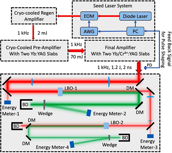
Figure 1.19. Schematic of the high average power, 1 J, green laser setup. The high power λ = 515 nm laser system includes a seed pulse laser front-end that generates pulses of arbitrary shape, a chain of diode-pumped Yb:YAG cryogenic amplifiers, and two sequentially placed LBO SHG units. DM, dichroic mirror; BD, beam dumper; PD, photodiode. Reprinted with permission from Chi et al [60] © The Optical Society.
Download figure:
Standard image High-resolution image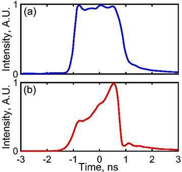
Figure 1.20. Temporal profiles of the (a) output pulse from the final amplifier, and (b) the seed pulse measured before the regenerative amplifier. Reprinted with permission from Chi et al [60] © The Optical Society.
Download figure:
Standard image High-resolution imageThe shaped seed pulses were amplified to an energy of >1.2 J at 1 kHz repetition rate by a chain of cryogenically-cooled Yb:YAG amplifiers similar to that described above, but in which the regenerative amplifier stage is also cryogenically cooled. LBO crystals cut at θ = 90° and ϕ = 13.6° for Type-I phase matching were placed at the output of the final amplification stage for upconversion into λ = 515 nm laser light. To make the most efficient use of the fundamental beam, two LBO crystals mounted on temperature-controlled copper holders at 300 K were set up in series as shown in figure 1.19. A Keplerian telescope was used to image the output of the Yb:YAG amplifier chain with selected demagnification onto the first LBO crystal (13 mm thick). The second-harmonic beam was separated from the fundamental by a sequence of two dichroic mirrors. The unconverted λ = 1030 nm beam was imaged into a second LBO crystal. Figure 1.21 shows the λ = 515 nm laser pulse energy and SHG conversion efficiency as a function of the λ = 1030 nm pulse energy obtained with the 13-mm-thick LBO crystal for a 14 mm diameter beam with a fluence of up to 0.78 J cm−2. The pulse energy reaches 0.94 J, corresponding to an average power of 940 W with a shot-to-shot standard deviation of 2.9% and a conversion efficiency of 78%. The unconverted beam was upconverted in the second LBO crystal, which generated additional >100 mJ pulses at λ = 515 nm. The resulting total λ = 515 nm average power reaches 1.04 kW (1.04 J pulses at 1 kHz repetition rate).
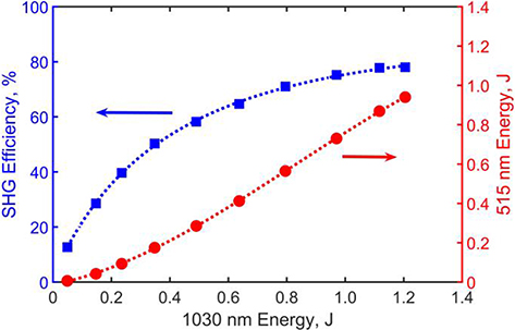
Figure 1.21. SHG efficiency (blue) and SHG output energy (red) vs. fundamental pulse energy obtained with a 13-mm-thick LBO crystal at 1 kHz repetition rate. Reprinted with permission from Chi et al [60] © The Optical Society.
Download figure:
Standard image High-resolution imageFigures 1.22(a) and (b) show that both the λ = 515 nm, 0.94 J and the secondary 100 mJ beams display flat-top profiles with good uniformity. The second-harmonic beam is characterized by a measured M2 = 1.40 and 1.32 on the horizontal and vertical directions, respectively (figure 1.22(c)).

Figure 1.22. Intensity profiles of the λ = 515 nm beams of pulse energy (a) 0.94 J, and (b) 100 mJ at 1 kHz repetition rate; (c) M2 measurement of the λ = 515 nm primary beam, and (d) beam profile at the focal spot. Reprinted with permission from Chi et al [60] © The Optical Society.
Download figure:
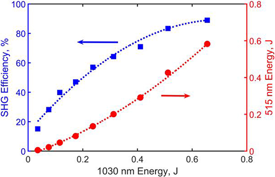
Standard image High-resolution imageAn even higher conversion efficiency of 89% was obtained with a 10-mm-thick LBO crystal when 0.65 J fundamental wavelength pulses were downsized to achieve a fluence of 0.83 J cm−2, as shown in figure 1.23.
Figure 1.23. SHG efficiency (blue) and SHG output energy (red) vs. fundamental energy obtained with a 10-mm-thick LBO crystal at 1 kHz repetition rate. Reprinted with permission from Chi et al [60] © The Optical Society.
Download figure:
Standard image High-resolution image
These SHG results will enable the generation of high energy laser pulses of femtosecond duration at 1 kHz repetition rate. In addition, the generation of Joule-level nanosecond pulses of arbitrary shape from a kW average power Yb:YAG laser system will benefit other applications such as heating tailored plasmas for extreme ultraviolet light generation.
1.5. Status and prospects
Yb:YAG picosecond lasers have already reached a pulse energy of 1 J at a repetition rate of 1 kHz. Further increases in both the average power and the pulse energy are expected. Yb:YAG is a mature, thoroughly studied material that is broadly available with high optical quality. It has the advantages of relatively long upper level lifetime that allows for efficient pumping with commercial high power laser diodes. It also has high thermal conductivity and small quantum defect, both of which ease the challenges of thermal management. In addition, Yb:YAG has a relatively broad spectral bandwidth that allows for the generation of picosecond pulses using chirped pulse amplification. These properties that make Yb:YAG attractive for the development of high average power, high energy ultrashort pulse lasers, further improve at cryogenic temperatures. When used in an active mirror geometry either in a thin disk geometry or in thicker gain medium geometries at cryogenic temperature, Yb:YAG enables the generation of Joule-level output pulses at record average powers. Compressed pulses of 720 mJ energy and 0.92 ps duration at 1 kHz repetition rate have been reported for a laser based on thin disks. A laser system based on cryogenically-cooled Yb:YAG has produced 1.1 J pulses of 4.5 ps duration at a 1 kHz repetition rate, an average power of 1.1 kW, which is a record for Joule-level picosecond lasers. These Joule-level high repetition rate lasers have already been used in applications that include pumping plasma-based soft x-ray lasers and producing filaments in the atmosphere to guide lightning. Future trends include the further increase in both the average power and the pulse energy, and the reduction of the pulse duration. Multi-Joule outputs at several kHz can be expected. Finally, while the pulse duration of these lasers has been bandwidth limited to about 1 ps, techniques for spectral broadening of high energy pulses are feasible and offer a path to femtosecond operation [61].
References
- [1]Danson C N et al 2019 Petawatt and exawatt class lasers worldwide High Power Laser Sci. Eng. 7 54
- [2]Moses E I, Boyd R N, Remington B A, Keane C J and Al-Ayat R 2009 The National Ignition Facility: ushering in a new age for high energy density science Phys. Plasmas 16 13
- [3]Kawanaka J, Yamakawa K, Nishioka H and Ueda K 2003 30-mJ, diode-pumped, chirped-pulse Yb:YLF regenerative amplifier Opt. Lett. 28 2121–23
- [4]Hong K H, Gopinath J T, Rand D, Siddiqui A M, Huang S W, Li E, Eggleton B J, Hybl J D, Fan T Y and Kartner F X 2010 High-energy, kHz-repetition-rate, ps cryogenic Yb:YAG chirped-pulse amplifier Opt. Lett. 35 1752–54
- [5]Papadopoulos D N, Pellegrina A, Ramirez L P, Georges P and Druon F 2011 Broadband high-energy diode-pumped Yb:KYW multipass amplifier Opt. Lett. 36 3816–18
- [6]Tummler J, Jung R, Stiel H, Nickles P V and Sandner W 2009 High-repetition-rate chirped-pulse-amplification thin-disk laser system with joule-level pulse energy Opt. Lett. 34 1378–80
- [7]Jung R, Tummler J, Nubbemeyer T and Will I 2016 Thin-disk ring amplifier for high pulse energy Opt. Express 24 4375–81
- [8]Zapata L E, Lin H, Calendron A L, Cankaya H, Hemmer M, Reichert F, Huang W R, Granados E, Hong K H and Kartner F X 2015 Cryogenic Yb:YAG composite-thin-disk for high energy and average power amplifiers Opt. Lett. 40 2610–13
- [9]Chang C L et al 2015 High-energy, kHz, picosecond hybrid Yb-doped chirped-pulse amplifier Opt. Express 23 10132–44
- [10]Metzger T, Schwarz A, Teisset C Y, Sutter D, Killi A, Kienberger R and Krausz F 2009 High-repetition-rate picosecond pump laser based on a Yb:YAG disk amplifier for optical parametric amplification Opt. Lett. 34 2123–25
- [11]Fattahi H, Alismail A, Wang H C, Brons J, Pronin O, Buberl T, Vamos L, Arisholm G, Azzeer A M and Krausz F 2016 High-power, 1-ps, all-Yb:YAG thin-disk regenerative amplifier Opt. Lett. 41 1126–29
- [12]Rand D A et al 2011 Picosecond pulses from a cryogenically cooled, composite amplifier using Yb:YAG and Yb:GSAG Opt. Lett. 36 340–42
- [13]Miller D E, Zapata L E, Ripin D J and Fan T Y 2012 Sub-picosecond pulses at 100 W average power from a Yb:YLF chirped-pulse amplification system Opt. Lett. 37 2700–2
- [14]Novak J et al 2016 Thin disk amplifier-based 40 mJ, 1 kHz, picosecond laser at 515 nm Opt. Express 24 5728–33
- [15]Fischer J, Heinrich A C, Maier S, Jungwirth J, Brida D and Leitenstorfer A 2016 615 fs pulses with 17 mJ energy generated by an Yb:thin-disk amplifier at 3 kHz repetition rate Opt. Lett. 41 246–49
- [16]Nubbemeyer T et al 2017 1 kW, 200 mJ picosecond thin-disk laser system Opt. Lett. 42 1381–84
- [17]Klingebiel S, Wandt C, Skrobol C, Ahmad I, Trushin S A, Major Z, Krausz F and Karsch S 2011 High energy picosecond Yb:YAG CPA system at 10 Hz repetition rate for pumping optical parametric amplifiers Opt. Express 19 5357–63
- [18]Morrissey F X, Fan T Y, Miller D E and Rand D 2017 Picosecond kilohertz-class cryogenically cooled multistage Yb-doped chirped pulse amplifier Opt. Lett. 42 707–10
- [19]Schmidt B E, Hage A, Mans T, Legare F and Woerner H J 2017 Highly stable, 54 mJ Yb-InnoSlab laser platform at 0.5 kW average power Opt. Express 25 17549–55
- [20]Herkommer C et al 2020 Ultrafast thin-disk multipass amplifier with 720 mJ operating at kilohertz repetition rate for applications in atmospheric research Opt. Express 28 30164–73
- [21]Furch F J, Reagan B A, Luther B M, Curtis A H, Meehan S P and Rocca J J 2009 Demonstration of an all-diode-pumped soft x-ray laser Opt. Lett. 34 3352–54
- [22]Reagan B A et al 2014 1 Joule, 100 Hz repetition rate, picosecond CPA laser for driving high average power soft x-ray lasers Conf. on Lasers and Electro-Optics (CLEO) (San Jose, CA: IEEE)
- [23]Baumgarten C, Pedicone M, Bravo H, Wang H C, Yin L, Menoni C S, Rocca J J and Reagan B A 2016 1 J, 0.5 kHz repetition rate picosecond laser Opt. Lett. 41 3339–42
- [24]Curtis A H, Reagan B A, Wernsing K A, Furch F J, Luther B M and Rocca J J 2011 Demonstration of a compact 100 Hz, 0.1 J, diode-pumped picosecond laser Opt. Lett. 36 2164–66
- [25]Zapata L E, Schweisthal S, Thesinga J, Zapata C, Schust M, Yizhou L, Calendron A-L, Pergament M and Kaertner F X 2019 Joule-class 500 Hz cryogenic Yb:YAG chirped pulse amplifier Conf. on Lasers and Electro-Optics Europe and European Quantum Electronics Conf. 2019 (Munich: Optical Society of America)
- [26]Wang Y, Chi H, Baumgarten C, Dehne K, Meadows A R, Davenport A, Murray G, Reagan B A, Menoni C S and Rocca J J 2020 1.1 J Yb:YAG picosecond laser at 1 kHz repetition rate Opt. Lett. 45 6615–18
- [27]Chenais S, Druon F, Forget S, Balembois F and Georges P 2006 On thermal effects in solid-state lasers: the case of ytterbium-doped materials Prog. Quantum Electron. 30 89–153
- [28]Aggarwal R L, Ripin D J, Ochoa J R and Fan T Y 2005 Measurement of thermo-optic properties of Y3Al5O12, Lu3Al5O12, YAIO(3), LiYF4, LiLuF4, BaY2F8, KGd(WO4)(2), and KY(WO4)(2) laser crystals in the 80–300 K temperature range J. Appl. Phys. 98 14
- [29]Calendron A L, Cankaya H and Kartner F X 2014 High-energy kHz Yb:KYW dual-crystal regenerative amplifier Opt. Express 22 24752–62
- [30]Siebold M, Bock S, Schramm U, Xu B, Doualan J L, Camy P and Moncorge R 2009 Yb:CaF2—a new old laser crystal Appl. Phys. B 97 327–38
- [31]Kuleshov N V, Lagatsky A A, Podlipensky A V, Mikhailov V P and Huber G 1997 Pulsed laser operation of Yb-doped KY(WO4)(2) and KGd(WO4)(2) Opt. Lett. 22 1317–19
- [32]Koechner W 2006 Solid State Laser Engineering (Berlin: Springer)
- [33]Ogawa K, Akahane Y, Aoyama M, Tsuji K, Tokita S, Kawanaka J, Nishioka H and Yamakawa K 2007 Multi-millijoule, diode-pumped, cryogenically-cooled Yb:KY(WO4)(2) chirped-pulse regenerative amplifier Opt. Express 15 8598–602
- [34]Liu H H, Nees J and Mourou G 2002 Directly diode-pumped Yb:KY(WO4)(2) regenerative amplifiers Opt. Lett. 27 722–24
- [35]Caracciolo E, Kemnitzer M, Guandalini A, Pirzio F, Agnesi A and Au J A D 2014 High pulse energy multiwatt Yb:CaAlGdO4 and Yb:CaF2 regenerative amplifiers Opt. Express 22 19912–18
- [36]Fan T Y, Ripin D J, Aggarwal R L, Ochoa J R, Chann B, Tilleman M and Spitzberg J 2007 Cryogenic Yb3+-doped solid-state lasers IEEE J. Sel. Top. Quantum Electron. 13 448–59
- [37]Machinet G et al 2013 High-brightness fiber laser-pumped 68 fs-2.3 W Kerr-lens mode-locked Yb:CaF2 oscillator Opt. Lett. 38 4008–10
- [38]Pugzlys A et al 2009 Multi-mJ, 200-fs, cw-pumped, cryogenically cooled, Yb,Na:CaF2 amplifier Opt. Lett. 34 2075–77
- [39]Albach D, Loeser M, Siebold M and Schramm U 2019 Performance demonstration of the PENELOPE main amplifier HEPA I using broadband nanosecond pulses High Power Laser Sci. Eng. 7 9
- [40]Hornung M et al 2016 54 J pulses with 18 nm bandwidth from a diode-pumped chirped-pulse amplification laser system Opt. Lett. 41 5413–16
- [41]Brunner F et al 2002 240-fs pulses with 22-W average power from a mode-locked thin-disk Yb:KY(WO4)(2) laser Opt. Lett. 27 1162–64
- [42]Brunner F et al 2000 Diode-pumped femtosecond Yb:KGd(WO4)(2) laser with 1.1-W average power Opt. Lett. 25 1119–21
- [43]Geusic J E, Marcos H M and Vanuitert L G 1964 Laser oscillations in Nd-doped yttrium aluminum yttrium gallium + gadolinium garnets (continuous operation of Y3A15O12, pulsed operation of Y3Ga5O15 + Gd3Ga5O12 rm temperature) Appl. Phys. Lett. 4 182
- [44]Russbueldt P, Mans T, Weitenberg J, Hoffmann H D and Poprawe R 2010 Compact diode-pumped 1.1 kW Yb:YAG Innoslab femtosecond amplifier Opt. Lett. 35 4169–71
- [45]Wynne R, Daneu J L and Fan T Y 1999 Thermal coefficients of the expansion and refractive index in YAG Appl. Opt. 38 3282–84
- [46]Dong J, Bass M, Mao Y L, Deng P Z and Gan F X 2003 Dependence of the Yb3+ emission cross section and lifetime on temperature and concentration in yttrium aluminum garnet J. Opt. Soc. Am. B 20 1975–79
- [47]Slack G A and Oliver D W 1971 Thermal conductivity of garnets and phonon scattering by rare-earth ions Phys. Rev. B 4 592
- [48]Liu Y, Demirbas U, Kellert M, Thesinga J, Cankaya H, Hua Y, Zapata L E, Pergament M and Kärtner F X 2020 Eight-pass Yb:YLF cryogenic amplifier generating 305-mJ pulses OSA Continuum 3 2722–29
- [49]Giesen A, Hugel H, Voss A, Wittig K, Brauch U and Opower H 1994 Scalable concept for diode-pumped high-power solid-state lasers Appl. Phys. B 58 365–72
- [50]Giesen A and Speiser J 2007 Fifteen years of work on thin-disk lasers: results and scaling laws IEEE J. Sel. Top. Quantum Electron. 13 598–609
- [51]Saraceno C J, Sutter D, Metzger T and Ahmed M A 2019 The amazing progress of high-power ultrafast thin-disk lasers J. Eur. Opt. Soc. Rapid Publ. 15 7
- [52]Jung R, Tummler J and Will I 2016 Regenerative thin-disk amplifier for 300 mJ pulse energy Opt. Express 24 883–87
- [53]Reagan B A, Curtis A H, Wernsing K A, Furch F J, Luther B M and Rocca J J 2012 Development of high energy diode-pumped thick-disk Yb:YAG chirped-pulse-amplification lasers IEEE J. Quantum Electron. 48 827–35
- [54]Reagan B A et al 2018 Scaling diode-pumped, high energy picosecond lasers to kilowatt average powers High Power Laser Sci. Eng. 6 e11
- [55]Chi H, Dehne K A, Baumgarten C M, Wang H C, Yin L, Reagan B A and Rocca J J 2018 In situ 3-D temperature mapping of high average power cryogenic laser amplifiers Opt. Express 26 5240–52
- [56]Gronloh B, Russbueldt P, Schneider W, Jungbluth B and Hoffmann H D 2012 High average power sub-picosecond pulse generation at 515 nm by extracavity frequency doubling of a mode-locked Innoslab MOPA Conf. on Solid State Lasers XXI—Technology and Devices (San Francisco, CA: SPIE—The International Society for Optical Engineering)
- [57]Rocker C, Loescher A, Bienert F, Villeval P, Lupinski D, Bauer D, Killi A, Graf T and Ahmed M A 2020 Ultrafast green thin-disk laser exceeding 1.4 kW of average power Opt. Lett. 45 5522–25
- [58]Phillips J P et al 2016 High energy, high repetition rate, second harmonic generation in large aperture DKDP, YCOB, and LBO crystals Opt. Express 24 19682–94
- [59]Bayramian A J et al 2009 High average power petawatt laser pumped by the Mercury laser for fusion materials engineering Fusion Sci. Technol. 56 295–300
- [60]Chi H, Wang Y, Davenport A, Menoni C S and Rocca J J 2020 Demonstration of a kilowatt average power, 1 J, green laser Opt. Lett. 45 6803–6
- [61]Fan G, Carpeggiani P A, Tao Z, Coccia G, Safaei R, Kaksis E, Pugzlys A, Légaré F, Schmidt B E and Baltuška A 2021 70 mJ nonlinear compression and scaling route for an Yb amplifier using large-core hollow fibers Opt. Lett. 46 896–99