


1. Introduction
Qualification procedures used in the space manufacturing industry aim at ensuring that a product, with its materials and manufacturing processes, meets design requirements (ISO 2008; Dordlofva Reference Dordlofva and Törlind2020). For traditional technologies such as forgings and castings and even weld assemblies, general qualification activities are well recognized and standardized. The predictability of final product property variation (regarding, e.g., material defects, microstructure variation etc.) is generally better than for additive manufactured products.
However, design specifications are less precise in early design phases and are continuously developed as the product development process advances. The uncertainty in design specifications is often accompanied by uncertainties in the manufacturing process, which requires designers to assess from experience and previous data how design choices will impact the qualification process. Casting technologies, for example, present an ample variation of material properties. When designing for casting, however, decades of experience allow designers to assess in early design phases how material variations might impact qualification and allow them to set experience-based design margins (Biliyard, Reference Biliyard2018).
However, the introduction of novel technologies raises the question on how design and qualification procedures need to be adapted to the new products? The lack of experience about design and qualification procedures for new technologies can lead to unexpected difficulties in designing a qualifiable product, resulting in expensive redesign processes and schedule delays (Engel & Barad Reference Elkaseer, Mueller, Charles and Scholz2003; Dordlofva et al. Reference Dordlofva, Borgue, Panarotto and Isaksson2019). Such is the case with the introduction of additive manufacturing (AM) in the space industry.
Based on nominal (average) values of material data, AM promises to enable weight (O’Brien Reference O’Brien, Helvajian, Piqué and Gu2018), lead times and costs reduction (Hopping & Xu Reference Hopping and Xu2017). However, the magnitude and interaction of factors that lead to material properties variations, such as material type, process parameters or powder quality, are still not well understood and documented in a way that is applicable for each individual AM design (O’Brien Reference O’Brien, Helvajian, Piqué and Gu2018). Unlike casting technologies, in addition to properties variation, the lack of experience in AM technologies complicates the experts’ assessment of AM components and the establishment of design specifications and safety margins (Dordlofva Reference Dordlofva and Törlind2020). For this reason, products might fail their qualification tests, resulting in expensive and lengthy redesign processes (Thomsen et al. Reference Thomsen, Kokkolaras, Månsson and Isaksson2017). In this context, manufacturers of space components have several options (Borgue et al. Reference Borgovini, Pemberton and Rossi2019):
-
(i) Develop novel AM designs ensuring their quality through exhaustive statistic-based testing and reliability methods in early design phases to reach sufficient confidence in material data (required by procedures such as failure mode, effects and criticality analysis (FMECA; Borgovini, Pemberton, & Rossi Reference Borgue, Müller, Leicht, Panarotto and Isaksson1993), usually involving between 300 and 900 test specimens (Seo et al. Reference Seo, Ahsan, Lee, Shin, Park and Kim2021). Considering that AM mechanical properties are dependent on part geometry, this strategy could lead to cost and schedule overrun if several possible product geometries are considered.
-
(ii) Avoid testing many specimens by developing a conservative design based on general AM guidelines [2]. In this way, the manufacturer develops a high-quality product but misses the opportunity of design exploration to develop a more radical and perhaps better design, leading to suboptimal designs with excessive design margins (Eckert, Isaksson, & Earl Reference Eckert, Isaksson and Earl2019).
-
(iii) Develop a novel AM design without performing much testing. Such a strategy facilitates design exploration and innovation. However, it is rarely acceptable in critical space applications to date but might be implemented in noncritical ‘safe-fail’ components (limits design applicability).
Authors such as Herzog (Reference Herzog2018), Mokhtarian et al. (Reference Mokhtarian, Hamedi, Nagarajan, Panicker, Coatanéa and Haapala2019) or Seo et al. (Reference Seo, Ahsan, Lee, Shin, Park and Kim2021) recommend a combination of the three strategies, proposing the early implementation of model-based design methods to reduce the number of tests needed and to evaluate the influence of design and process parameters on component quality to establish data-based design margins.
At present, however, there is a lack of methods to overcome the lack of experience about AM technologies and quantitatively include AM uncertainties early in the design loops, to support the development of qualifiable products (Brice, Reference Brice2011).
Modelling and quantifying the impact of AM process variation on a product’s qualification ability would support the identification of design features where further testing is required (and affordable) to establish tighter design margins. The classical approach to reduce uncertainty and variation of materials through test campaigns is found to be too expensive, which is why there is a need to find alternative strategies to assess qualification strategies when designing for AM. For this reason, the study presented in this article aims at answering the research question:
RQ: How can AM process uncertainties and their impact on qualification be modelled and included in early design phases?
The attractiveness of AM to offer better design freedom governs the necessity to better know the consequences and possible risks of relying on AM technologies already in the conceptual stages. For safety critical and weight optimized components, qualification is critical, and likeliness to successfully qualify the product is decisive.
In this article, a model-based design for qualification method is proposed that aims at supporting the conceptual design of AM components for space applications with affordable test phases. Through the implementation of fuzzy logic techniques, experts’ assessment of AM properties variation is modelled to develop a quantitative metric for qualification ability. The novelty of the method lies on utilizing the quantitative metric for qualification ability to elaborate qualification maps that model the impact of design parameters and their interactions, on a product’s qualification ability. The implementation of qualification maps supports reducing the amount of test specimens and identifying the design parameters where further testing is valuable to establish tighter design margins. Design parameters where further testing is excessively costly or time-consuming can be assigned larger design margins.
A detailed design case from the implementation of AM technologies in the manufacturing of satellite propulsion systems is developed to demonstrate the method.
2. Background
Qualification activities are test activities which are performed to demonstrate that a product meets its design, quality and reliability requirements as well as safety and legislative norms (ISO 2008; Dordlofva Reference Dordlofva and Törlind2020). Similar objectives can also be attributed to the verification, validation and testing activities performed in the systems engineering field (Shabi, Reich, & Diamant Reference Shabi, Reich and Diamant2017); moreover, the systems engineering ISO standard 15288 that include processes and lifecycle stages draws a parallel between verification activities and qualification (ISO 2015).
For already established manufacturing technologies, several qualification standards that guide qualification activities exist. Such is the case of NASA qualification standards for casting NASA-STD-6016 (Materials), -5009 (Nondestructive Tests), -5012 (Structures) and -5019 (Fracture Control; Biliyard Reference Biliyard2018). According to standards and common practices (NASA 1970), each qualification test had its own pass/fail criteria determined before the test is performed. In the case of qualification tests to assess component response to environmental loads, for instance, a test can be considered failed when the presence of fatigue cracks, excessive structural deformation or instabilities are observed in the component after the test.
The criteria for the evaluation of qualification tests are often identified and formulated from an FMECA study (Borgovini et al. Reference Borgue, Müller, Leicht, Panarotto and Isaksson1993, where criticality of failure modes is identified and their impact is assessed. Potential failure modes are classified according to their impact on the system and can be utilized to complement, among other things, an assessment of components and subsystems criticality.
In early design phases, product design specifications and associated loads (including those related to failure modes and their criticality) are not completely established and are typically evolved and refined as the product development process advances. The insufficient precision in defined design specifications pose a problem when designing qualifiable products. Designers must assess from experience, early testing activities and previous projects data how design choices will impact the qualification processes (Borgovini et al. Reference Borgue, Müller, Leicht, Panarotto and Isaksson1993). In this context, design development and qualification are performed iteratively during product development; however, design iterations due to failed qualification tests can incur in expensive delays on a product development schedule (Dordlofva et al. Reference Dordlofva, Borgue, Panarotto and Isaksson2019).
Authors such as Pecht (Reference Pecht1993), Preussger, Kanert, & Gerling (Reference Preussger, Kanert and Gerling2003), Yadav, Singh, & Goel (Reference Yadav, Singh and Goel2006) or Dordlofva & Törlind (Reference Dordlofva2018) sustain that to reduce design iterations due to failed qualification tests, qualification procedures and requirements need to be addressed in the early stages of a product development process.
Pecht (Reference Pecht1993), Preussger et al. (Reference Preussger, Kanert and Gerling2003) and Yadav et al. (Reference Yadav, Singh and Goel2006), for instance, have proposed methodologies and guidelines for the electronics industry focusing on reliability assessment, test activities and test planning early in the development process. However, a continuation of their work, including guidelines for approaching product design considering how the product should be qualified, is still missing.
FMECA (Borgovini et al. Reference Borgue, Müller, Leicht, Panarotto and Isaksson1993) is often included as a mandatory activity within the development process, and since it identifies risks and require mitigation plans, it typically drives design and analysis iterations to reduce uncertainties and reach satisfactory reliability. However, these methods are often criticized since quantifying consequences may require extensive test campaigns, being labour and cost intensive (Eastman Reference Eastman2012). One reason is the quantitative nature of risk identification, which is often based on experience, whereas the effort to resolve the potential risks can be substantial.
In the work by Dordlofva et al. (Reference Dordlofva, Borgue, Panarotto and Isaksson2019), the authors proposed a method for identifying factors that motivate and influence product qualification, called ‘qualification drivers’. The identification of qualification drivers is intended to reduce the amount of required testing and support the development of Design for Qualification guidelines and methods. Nevertheless, the authors did not propose qualification guidelines or quantifiable ways to link the influence of design parameters with qualification procedures. Moreover, it is assumed in their method that there is enough information about qualification activities and requirements already in early design phases.
When introducing a new technology, in early design phases, the problem related to loosely defined qualification requirements is aggravated with the lack of experience about designing and qualifying a product with the new technology.
2.1. Qualification of AM components
Although there is a growing interest to introduce AM to reduce weight, cost and time to market (O’Brien Reference O’Brien, Helvajian, Piqué and Gu2018; Dordlofva Reference Dordlofva and Törlind2020), most examples of AM parts that have been successfully developed and implemented in the space industry are noncritical (O’Brien Reference O’Brien, Helvajian, Piqué and Gu2018). This means that a failure can be accepted without fatal consequences, and the margins can be narrowed down and accepted. The consequence and criticality of the risks identified in an FMECA are consequently lower for noncritical products. The lack of critical space components manufactured using AM is mostly due to qualification of AM still being a challenge (Seifi et al. Reference Seifi, Gorelik, Waller, Hrabe, Shamsaei, Daniewicz and Lewandowski2017), as there is a lack of understanding of AM processes (Thomsen et al. Reference Thomsen, Kokkolaras, Månsson and Isaksson2017) and a lack of standardized approaches to ascertain the quality of AM parts (Shabi et al. Reference Shabi, Reich and Diamant2017). The statistical spread in properties is not acceptable for critical products.
The need to support engineers early in product development to allow them to explore the design potentials enabled by AM is often highlighted, such designs for AM (DfAM) methods and strategies have been previously reviewed by authors such as Gibson et al. (Reference Gibson, Rosen, Stucker and Khorasani2021). However, there is little focus on methods to explicitly support engineers in designing products that can be qualified, especially for critical applications such as satellite components (O’Brien Reference O’Brien, Helvajian, Piqué and Gu2018; Dordlofva Reference Dordlofva and Törlind2020).
AM parts exhibit characteristics that are challenging for engineers designing for AM, such as anisotropic and location-dependent material properties, material defects (such as cracks, pores or lack of fusion) or rough surfaces. It has also been shown that part geometry impacts these material characteristics (Seifi et al. Reference Seifi, Gorelik, Waller, Hrabe, Shamsaei, Daniewicz and Lewandowski2017), putting additional responsibility on engineers to understand the capabilities of AM processes, and to design qualifiable AM components. The lack of understanding and previous experience with AM contributes to lengthy and expensive FMECA activities and the development of AM products with ample design margins (Eckert et al. Reference Eckert, Isaksson and Earl2019) that might undermine the weight reduction benefits from this technology.
Dordlofva (Reference Dordlofva and Törlind2020) introduced a design for qualification framework for AM that proposes to design a product concurrently with its qualification process. To account for loosely defined qualification requirements in early design phases, the author proposes over-dimensioned safety factors, such as those implemented for casting technologies (Dordlofva & Törlind Reference Dordlofva2018; Eckert et al. Reference Eckert, Isaksson and Earl2019). The author, however, does not provide explicit guidelines to propose those safety factors. In the case of casting technologies, those safety factors are established through data from previous projects and experts’ experience, in AM; however, the lack of knowledge about the technology renders this assessment difficult.
To address the lack of knowledge about AM and to be able to establish those safety factors at the expense of product weight and without performing exhaustive and expensive tests (Borgovini et al. Reference Borgue, Müller, Leicht, Panarotto and Isaksson1993; Seifi et al. Reference Seifi, Gorelik, Waller, Hrabe, Shamsaei, Daniewicz and Lewandowski2017), authors such as Seo et al. (Reference Seo, Ahsan, Lee, Shin, Park and Kim2021), Herzog (Reference Herzog2018) or Mokhtarian et al. (Reference Mokhtarian, Hamedi, Nagarajan, Panicker, Coatanéa and Haapala2019), recommend the early implementation of model-based design methods (Wall Reference Wall2004).
In contrast to design methods based on text descriptions and drawings, model-based design methods capture designs in a model environment for design analysis and simulations purposes, facilitating information sharing and collaboration (Wall Reference Wall2004). Model-based methods can reduce the consequences of AM uncertainties and implement the little data and experience available about AM, to evaluate the influence of design and process parameters on component quality.
2.2. Fuzzy logic implemented in the product development process
One type of model-based methods to support problem-solving when sources of uncertainty are involved are fuzzy logic methods (Ross Reference Ross2004). Probability is related to the frequency of occurrence of events, captured by repeated experiments. Fuzzy logic methods, on the other side, provide a framework for evaluating the possibility of events rather than their probability (Ross Reference Ross2004).
In fuzzy theory, the possibility of events is represented through fuzzy membership functions. A membership function μA(x) for a fuzzy set A on the universe of X is defined as μA:X → [0, 1]. Each element of X is mapped with a membership value between 0 and 1. Each membership function μA(x) ∈ [0, 1]. If μA(x) = 0, it implies that x ∉ A. On the other hand, if μA(x) = 1, then x ∈ A (Zimmermann Reference Zimmermann2012). The shape of a membership function is adapted to the data it represents (Ross Reference Ross2004). In Figure 1, triangular and trapezoidal membership functions, μ(T), are used to model people’s perception of different temperatures. At 19 °C, some people will feel cold (70%), whereas other will feel warm (30%); at 26 °C, some people will feel warm (90%) and some other hot (10%). At 15 °C, everyone agrees that is cold, and at 35 °C, everyone agrees that is hot (e.g., based on the content of the work by Zimmermann (Reference Zimmermann2012)).

Figure 1. Triangular membership functions modelling people’s perception of different temperatures (°C).
One of the main benefits of fuzzy logic is to approximate the behaviour of a system when analytic representations do not exist. Hence, they are inherently useful for dealing with complex systems, such as engineering design systems, where multiple inputs and outputs cannot be captured analytically (Ross Reference Ross2004).
In this context, one of the most widely implemented fuzzy logic techniques is Mamdani inference (Izquierdo & Izquierdo Reference Izquierdo and Izquierdo2017). Mamdani fuzzy systems were developed to describe operators’ decisions when controlling processes with a set of linguistic IF-THEN rules, to be then used by a machine to automatically control the same processes (Izquierdo & Izquierdo Reference Izquierdo and Izquierdo2017). This method is especially appropriate when sophisticated mathematical models are not needed, and where experts’ knowledge and experience can be easily included in the model structure (Precup & Preitl Reference Precup and Preitl2004).
Another widely implemented fuzzy logic technique is Sugeno interference (Hamam & Georganas Reference Hamam and Georganas2008). Its main difference with respect to Mamdani interference is its outcome; Mamdani interference enables fuzzy outcomes which can be then defuzzified (crisp outcome). Sugeno interference directly provides a crisp outcome. Consequently, Mamdani interference provides a higher expressive power and more nuanced and interpretable results, which makes it a better fit for decision support applications (Ross Reference Ross2004; Hamam & Georganas Reference Hamam and Georganas2008).
These characteristics render Mamdani fuzzy logic increasingly attractive for product development applications. The main advantage of these approaches is that they systematically implement experts’ assessments in a quantifiable manner, which is rarely the case on product development processes, as can be found in the work by Saridakis & Dentsoras (Reference Saridakis and Dentsoras2005) or Boujour et al. (Reference Bonjour, Deniaud, Dulmet and Harmel2009). These authors implemented fuzzy logic for supporting model-based product design activities in early phases. Such studies, however, are not concerned with designing qualifiable products for novel technologies, such as AM.
Other authors (Elkaseer et al. Reference Engel and Barad2018; Lanzotti et al. Reference Lanzotti, Carbone, Grazioso, Renno and Staiano2018) have implemented Mamdani fuzzy sets in designing for AM strategies for considering the uncertainty of AM processes outcomes. In their work, Elkaseer et al. (Reference Engel and Barad2018), for instance, developed a fuzzy logic-based algorithm that mimicked knowledge-based expert systems to automatically take corrective actions to improve printing quality. Lanzotti et al. (Reference Lanzotti, Carbone, Grazioso, Renno and Staiano2018) implemented a fuzzy approach for supporting the evaluation and selection of optimal design concepts where AM alternatives were evaluated. In these articles, however, the insights obtained from the fuzzy logic methods are not fed back to early design stages to improve a design.
Fuzzy logic methods seem to be appropriate to support the introduction of AM technologies in the space industry. These methods can be an asset for modelling AM manufacturing uncertainties without incurring into long and expensive test phases to attain the statistical determination of material properties and probabilistic assessment of qualification risk (Brice Reference Brice2011).
3. Research methodology
An application where qualification impacts and sometimes hinders the implementation of new technologies, such as AM, was identified in the context of an advanced manufacturing demonstration program, with the objective of developing the next generation of electric satellite propulsion systems.
In this context, this article is focused on the activities concerning the qualification of a high-power electric propulsion system (EPS) adopted on interplanetary missions. The focus of the study is the conceptual design of the thruster unit (TU) from an EPS and the design decisions made around its components design when the implementation of AM is intended.
The core of the data collection activities for this study was performed through a 3-month study visit at a company manufacturer of EPS systems and various satellite components. During that period, the authors worked on site, in close collaboration with the company design team of the present technology program where full access to real design and qualification company data was provided. Moreover, it enabled continuous interactions with designers while they made real design decisions.
However, the on-site visit was a part of a 4-year project, from 2017 to 2021, period where the industrial partners developed and tested the EPSs. The researchers attended the project, prepared the 3-month study and have follow-up with the company after the 3-month focus study was over.
From the study, a fuzzy model-based method for assessing the impact of design parameters on the outcome of qualification procedures and for including these insights in early design phases was developed. The method aims at supporting design exploration and design decisions to develop qualifiable products. To illustrate its implementation, the method was applied in a sample case study featuring the redesign for AM of two components in a TU of a propulsion system for space exploration.
4. Model-based design for qualification for additively manufactured space components
In this section, a model-based design method that supports the affordable introduction of AM technologies in space components is presented. The method implements fuzzy logic techniques for modelling qualification requirements during conceptual design phases. Fuzzy logic techniques were preferred due to the unpredictable nature of AM defects and their ill-defined influence on product quality (Seifi et al. Reference Seifi, Gorelik, Waller, Hrabe, Shamsaei, Daniewicz and Lewandowski2017; Seo et al. Reference Seo, Ahsan, Lee, Shin, Park and Kim2021).
In Figure 2, the proposed method is presented. The necessary inputs for the method are overall product architecture and test and qualification plan, a datasheet of the components intended to be redesigned for AM and general AM design guidelines (Diegel, Nordin, & Motte Reference Diegel, Nordin and Motte2019; Gibson et al. Reference Gibson, Rosen, Stucker and Khorasani2021).

Figure 2. Model-based method for design for qualification.
4.1. Step 1: identification of design parameters that influence qualification
In this step, component design parameters that can affect the outcome of qualification activities (pass/fail) are identified. Due to the additive nature of AM technologies, design parameters can influence the presence of unexpected material defects, microstructure variations or geometrical deformations (among others) that might have a negative influence in the qualification processes. The stair stepping effect observed in angled surfaces, for instance, is the main cause of low surface quality (Herzog Reference Herzog2018). If a component requires a specified surface roughness, qualification activities will be performed to ensure compliance with this design requirement. If the surface cannot be treated to improve its surface finishing, surface inclination angle is a design parameter that can influence the outcome of qualification activities. Such a case is presented in depth in the work by Dordlofva (Reference Dordlofva and Törlind2020), when designing the untreatable internal surfaces of a manifold for a rocket engine.
4.2. Step 2: establishment of membership functions
Each design parameter identified in Step 1 is assigned a membership function whose shape should be chosen to fit the design parameter dataset. In Figure 3, an example of how the shape of a membership function is established is presented.
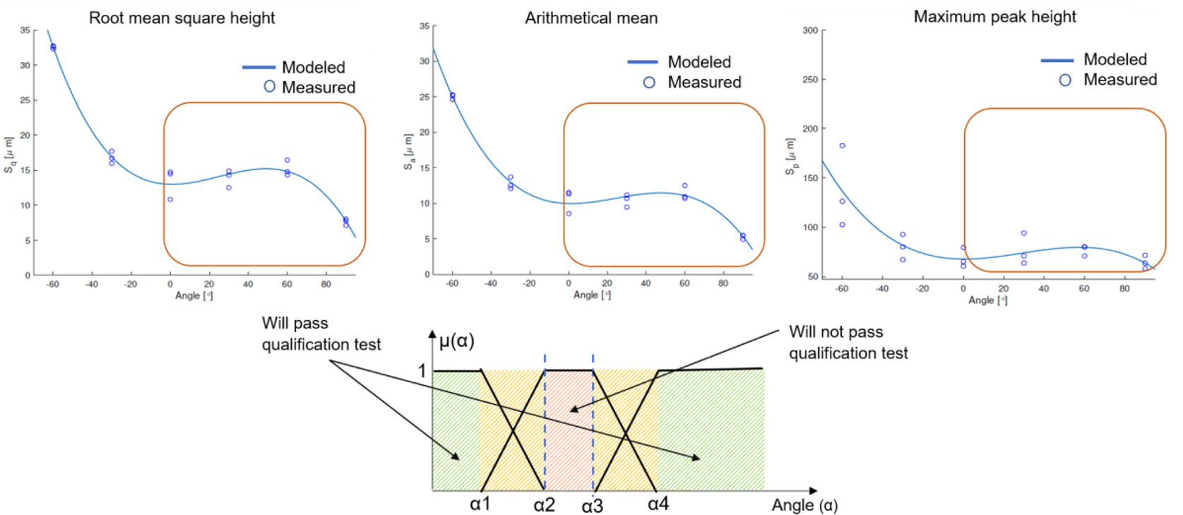
Figure 3. Top: surface roughness data (Herzog Reference Herzog2018). Bottom: membership function.
In Figure 3, the membership function μ(α) for the surface inclination angle, α, and its influence on the outcome of the qualification tests is trapezoidal, and obtained from the root-mean-square height, arithmetical mean and maximum peak height data. High surface quality is achieved in completely horizontal (90°) and vertical surfaces (0°) (Herzog Reference Herzog2018). The worst surface roughness seems to be obtained from a range of angles that starts at ~30° and covers angles up to ~70° (three graphs from the top of Figure 3). If the component requires a smooth surface, after a certain threshold angle (~30°), there is a range of angles where the surface becomes too rough (~30° to ~70°), resulting in a failed qualification test (red area in the bottom of Figure 3). Angles below ~30 and above ~70 are more likely to result in a high likelihood of a successful qualification.
Design requirements would determine which surface roughness ranges are acceptable and which are not, which is essentially the establishment of the membership function parameters α2 and α3, from the red zone in the bottom of Figure 3. Due to the complex physical phenomena taking place in AM and the sometimes-unpredictable nature of the manufacturing outcome (Thomsen et al. Reference Thomsen, Kokkolaras, Månsson and Isaksson2017; Sanaei, Fatemi, & Phan Reference Sanaei, Fatemi and Phan2019; Dordlofva Reference Dordlofva and Törlind2020), surface angles lower than α2 and higher than α3 might still present rough surfaces and compromise component compliance with qualification requirements. Some α values might result in a failed qualification test but might also result in a successful one (orange zone).
4.3. Step 3: assessment of membership function parameters
When a membership function is selected for each design parameter, the membership function parameters must be established. In this step, design specifications are assessed to determine when x ∈ A (μA(x) = 1) and when x ∉ A (μA(x) = 0).
For aerospace grade metallic materials, the qualification procedure for introducing a new alloy is rigorous (Seo et al. Reference Seo, Ahsan, Lee, Shin, Park and Kim2021). Minimum design values that should be considered as membership function parameters are based on component criticality and established through thorough statistical procedures. Critical, nonredundant structures usually require A-basis minimum values, where the minimum data requirement for material properties is around 300 samples for an isotropic material and 900 samples for anisotropic materials. However, the amount of testing required to fully define the mechanical behaviour of the material (both static and dynamic perspectives) might require thousands of individual tests (Brice Reference Brice2011; Seo et al. Reference Seo, Ahsan, Lee, Shin, Park and Kim2021). This rigorousness, however, delays time to market, increases costs and hinders innovation and the introduction of new technologies to aerospace components (Brice Reference Brice2011). Currently, if two different manufacturing processes for the same material are used to manufacture a component, current practices treat them as two different materials because the microstructures cannot be proved to be identical (Brice Reference Brice2011). In the case of AM, mechanical properties and microstructure are also dependent on part geometry (Seifi et al. Reference Seifi, Gorelik, Waller, Hrabe, Shamsaei, Daniewicz and Lewandowski2017), which requires different geometries to be treated as different materials during the material qualification processes. Such rigorous test strategies might not be affordable in scenarios where design exploration is desired.
An alternative pathway for the thorough statistical procedures is using experts’ opinions for establishing membership function parameters. A similar approach was proposed by Dordlofva (Reference Dordlofva and Törlind2020) in the study of the AM manifold, where overconservative AM safety factors were determined by company practitioners. In this context, the determination of the membership function parameters is closely related to the determination of AM safety factors, which can be established with an assessment of available AM inspection methods or postprocessing techniques. Moreover, the assessment of these parameters can be related to qualification schedule and cost. If the component under analysis is part of the critical path of the general product qualification activities, stringent parameters can be applied to reduce the risk of failing qualification tests and incurring in redesign procedures that can delay overall product qualification.
Since experts’ experience is in general vague and hard to capture, a multi-expert multi-criteria decision-making (ME-MCDM) fuzzy approach is implemented (Elkaseer et al. Reference Engel and Barad2018) in this step. The proposed ME-MCDM fuzzy approach is supported by an ordered weighted average (OWA) technique (Yager Reference Yager2004), for combining different experts’ opinions. This approach has been successfully tested by authors such as Saridakis & Dentsoras (Reference Saridakis and Dentsoras2005), Elkaseer et al. (Reference Engel and Barad2018) and Lanzotti et al. (Reference Lanzotti, Carbone, Grazioso, Renno and Staiano2018).
As the quality and reliability of their assessments depends on the experience of each expert (Johansson et al. Reference Johansson, Hicks, Larsson and Bertoni2011), they provide their opinions in the shape of fuzzy sets which are then weighted according to an established weighting system. These fuzzy sets are proposed (before the weighting process) as triangular functions which can be interpreted as a main parameter value (triangle top vertex) considered with a certain error defined by the lateral triangle vertices. Their opinions are aggregated and then defuzzified following Eq. (1) (Ross Reference Ross2004; Saridakis & Dentsoras Reference Saridakis and Dentsoras2005; Zimmermann Reference Zimmermann2012), which represents the centroid of all the considered fuzzy sets:
 $$ centroid=\frac{\int x\ast \mu A(x)}{\int \mu A(x)}, $$
where μA(x) is the membership function value for x.
If a specific x has more than one membership function associated, the equation considers the value of the μ(x) function with the highest value.
There are numerous defuzzification methods, and their selection is context-dependent. For this study, the centroid method was preferred due to its popularity and computational convenience when defuzzifying simple membership functions; however, other methods might yield similar results (Ross Reference Ross2004; Zimmermann Reference Zimmermann2012).
Following the surface roughness example, three experts would evaluate each membership function parameter α1 and α2, providing an error margin in their estimations. The designers have weights of (0.9, 0.8, 0.6) according to their experience in the field in DfAM. In Figure 4, each designer’s fuzzy set is presented for the parameters α1 and α2. The sets are cut at levels corresponding to their opinion weighting. The area formed by all the fuzzy sets after the weighting process is then defuzzified, finding the centroid of the formed area with Eq. (1).

Figure 4. Fuzzy sets from three experts to obtain parameters α1 and α2 to be used in the membership function for assessing surface inclination and its effect on qualification.
4.4. Step 4: development of fuzzy design for qualification maps
Having established the parameters of every membership function, those functions can be combined to create qualification maps, as the one exhibited in Figure 5. In Figure 5, the combination of the parameters α (surface inclination angle) and τ (wall thickness), and its impact on likelihood of a successful qualification test, is presented.

Figure 5. Qualification map for two generic design parameters α and τ.
Qualification likelihood for α, μ(α), is added to qualification likelihood for τ, μ(τ), creating a three-dimensional plot of qualification likelihood (evaluated from 0 to 1), α and τ. Every point in the plot is defined by the value [α, τ, μ(α) + μ(τ)], and the qualification likelihood is then scaled to provide values from 0 to 1.
These qualification maps map the design space according to their likeliness to pass qualification tests. In the surface roughness example, μ(α) is mapped against a μ(τ) which represents the possibility of failing a qualification test depending on the wall thickness, τ. Both thin walls and rough surfaces are in high risk of failing the qualification tests. The combination of the two reduces qualification likelihood even further.
4.5. Step 5: design for qualification
The qualification map helps the visualization of design alternatives and their assessment regarding qualification. It can be used, for example, in a multidisciplinary design trade-off analysis to compare different product concepts. The map, however, is intended to be a dynamic tool, a way for designers to assess which parameter combinations can result in qualifiable products and then use that information when comparing alternative designs and making design- and test-related decisions. If a design alternative is superior to others in some ways but it is located in an orange zone in a qualification map, it is an indication that the design might not pass a qualification test. In this case, extra material testing activities can be performed to redefine that specific orange zone and perhaps reduce the distance between α1 and α2, and α3 and α4. In this case, the qualification map indicates where it is worth it to perform extra testing and where it is not. This feature enables the development of a design exploration strategy for the development of a high-quality product while reducing the test phases related to the material qualification of numerous different geometries.
Different companies and different products with the same design parameters (such as α or τ) will likely have different membership function parameters (different α1, α2, α3 and α4) due to the variability of human assessment and the variation of component requirements among companies. This fact suggests that a qualification map can support questioning the established design specifications and AM safety factors (is it necessary to have such a smooth surface?), as they are not inherently fixed.
AM data obtained from the implementation of the proposed model can be formalized and documented in the qualification maps, or in various design/documentation platforms such as those proposed by Borgue et al. (Reference Borgovini, Pemberton and Rossi2019) and be reused in future development projects.
5. Model-based design for qualification of additively manufactured gridded ion thruster components
In this section, the developed model-based design for qualification method is implemented in the redesign for AM of two components of a TU in a gridded ion thruster with an approximate diameter and height of 20 cm and 12 cm, respectively. A CAD model of the TU is presented in Figure 6. A thorough description of the functionality of a TU can be found in Kindberg (Reference Kindberg2017).

Figure 6. CAD model of a gridded thruster. To the right, chamber and shell to be redesigned for AM.
The anode and the external shell are intended to be redesigned for AM. In the anode, the propellant is ionized and then accelerated. This component requires a smooth internal surface and is machined from a metal block to form the anode geometry. The anode is usually in contact with the ‘screen grid’, the first grid of a series of three acceleration grids (Kindberg Reference Kindberg2017).
The external shell, on the other side, encloses the internal TU circuitry and provides a general protective function. This component is manufactured with soft iron.
Redesigning these two components for AM can reduce component weight, to satisfy industry requirements for cost-efficient space systems (Öhrwall Rönnbäck & Isaksson Reference Öhrwall Rönnbäck and Isaksson2018; Diegel et al. Reference Diegel, Nordin and Motte2019), and overall manufacturing costs, as AM processes can reduce costs of tooling and machining and require less skilled labour forces (Hopping & Xu Reference Hopping and Xu2017).
Using DfAM guidelines, such as those proposed in literature (Diegel et al. Reference Diegel, Nordin and Motte2019; Gibson et al. Reference Gibson, Rosen, Stucker and Khorasani2021), the shell is redesigned for AM with the inclusion of diamond-shaped holes in the protective walls (Figure 7a), to reduce its overall weight. In this design, three parameters can influence qualification: wall thickness, number of diamond-shaped holes and separation between holes.

Figure 7. External shell and anode to be redesigned for AM.
The presence of AM defects, such as pores, lack of fusion or cracks, can lead to catastrophic failure of thin AM walls and clustered holes (Villarraga-Gómez et al. Reference Villarraga-Gómez, Peitsch, Ramsey and Smith2018; Sanaei et al. Reference Sanaei, Fatemi and Phan2019). Moreover, Sanaei et al. (Reference Sanaei, Fatemi and Phan2019) reported that surface proximity can negatively influence defect size and density, which can affect functionality (or the outcome of a qualification test) in a component with a large number of surface holes.
The AM anode design is optimized including a curved bottom (Figure 7b) and is designed to be integrated with the screen grid. This integrated design is based on two parameters that can influence the outcome (pass/fail) of qualification procedures: grid wall thickness τ, and angle of the anode wall α. The anode thickness is not modified as is a component from the magnetic circuit and is designed to carry the magnetic flux from the magnets.
The surface inclination angle in the anode will affect the component orientation in the building chamber to avoid internal support structures. Rough surfaces [product of stair stepping effects (Herzog Reference Herzog2018) from various component orientations in the building platform] in the outside surface of the screen grid can enable arcing between this grid and the next one. If the grid is too thin, those surface defects cannot be machined out.
For supporting design exploration and decision-making regarding the design parameters, the proposed model-based design method is implemented.
In Figure 8, fuzzy membership functions for the design parameters that influence qualification outcome for the shell and the anode are presented. In the case of the protective shell, there is no number of holes that ensures a successful qualification; therefore, μ(N) contains only orange and red zones. The orange and red qualification map is not necessarily a ‘showstopper’, but is just an indication that future qualification problems might arise in the orange zone. With this information, designers can propose different strategies such as eliminating holes, increasing design margins or strengthening the external shell with an additional component.

Figure 8. Membership functions for design parameters that can influence qualification outcomes.
In the case of the anode, when the surface inclination angle increases, there is the possibility of sandblasting the surface to improve its roughness. However, rougher surfaces in the outside of the grid would need larger proportions of its thickness removed, which can result in compromising structural integrity.
Implementing an ME-MCDM (Saridakis & Dentsoras Reference Saridakis and Dentsoras2005) fuzzy approach, a panel of experts negotiates the parameters of the membership functions introduced in Figure 8 (the starting points of the different colour zones). As Dordlofva (Reference Dordlofva and Törlind2020) proposed, their assessment should be based on three pillars:
-
(i) current relevant material data,
-
(ii) additional AM safety margins and
-
(iii) process control and inspection.
Relevant material data and process control can be performed through the implementation of product tailored test artefacts (Dordlofva Reference Dordlofva and Törlind2020), to evaluate the influence of geometry and process parameters on the manufacturing outcome. As AM mechanical properties are geometry-dependent (Seifi et al. Reference Seifi, Gorelik, Waller, Hrabe, Shamsaei, Daniewicz and Lewandowski2017), the combination of experts’ assessment and product tailored test artefacts is intended to identify which geometries should undergo a more rigorous test process (statistical analysis), reducing in the end the number of test specimens. Insights on how to design tailormade test artefacts can be found in the work by Borgue et al. (Reference Borgovini, Pemberton and Rossi2019). With an OWA technique (Yager Reference Yager2004), the different experts’ assessments are combined.
The weights assessment is context-dependent and reflects the perhaps subjective importance or experience of each expert regarding design, qualification or AM. Experts’ assessments are then defuzzified for determining the membership function parameters, implementing the centroid Eq. (1) and exemplified in Figure 9. On the top of Figure 9, experts’ assessments for the membership functions parameters presented in Figure 8 for the external shell (number of holes N, and thicknesses τc1, τc2, τn1 and τn2) and for the anode (inclination angles α1 and α2, and thicknesses τ1 and τ2) are presented.

Figure 9. Membership function parameters’ assessment with their calculated centroid. Each expert provides their assessment through a central value with error margins.
The parameters’ values according to the different experts are summarized on a table at the bottom of Figure 9. For obtaining the parameters’ values for the qualification maps, the MATLAB built-in methods for Mamdani fuzzy inference system defuzzification were implemented. The centroid was obtained through Eq. (1) with an error obtained considering on the outmost values provided by the experts. The table results are summarized below:
External shell: N =
 $ {4.0}_{-1.8}^{+1.8} $
holes/cm2; τc1 =
$ {4.0}_{-1.8}^{+1.8} $
holes/cm2; τc1 =
 $ {1.0}_{-0.7}^{+0.7} $
mm; τc2 =
$ {1.0}_{-0.7}^{+0.7} $
mm; τc2 =
 $ {2.0}_{-1.5}^{+1.7} $
mm; τn1 =
$ {2.0}_{-1.5}^{+1.7} $
mm; τn1 =
 $ {0.20}_{-0.15}^{+0.10} $
mm; τn2 =
$ {0.20}_{-0.15}^{+0.10} $
mm; τn2 =
 $ {0.40}_{-0.15}^{+0.15} $
mm.
$ {0.40}_{-0.15}^{+0.15} $
mm.
Anode: α1 = (
 $ {20}_{-8}^{+8} $
)°; α2 = (
$ {20}_{-8}^{+8} $
)°; α2 = (
 $ {40}_{-5}^{+9} $
)°; τ1 = (
$ {40}_{-5}^{+9} $
)°; τ1 = (
 $ {2}_{-1}^{+2} $
) mm; τ2 = (
$ {2}_{-1}^{+2} $
) mm; τ2 = (
 $ {4}_{-2}^{+2} $
) mm.
$ {4}_{-2}^{+2} $
) mm.
The main objectives when redesigning these two components for AM are reducing costs, lead times (Hopping & Xu Reference Hopping and Xu2017) and component weight (Öhrwall Rönnbäck & Isaksson Reference Öhrwall Rönnbäck and Isaksson2018).
In Figure 10, qualification maps for the chamber and the shell are presented. The maps were build utilizing the MATLAB fuzzy logic designer. On the maps from Figure 10a, the coloured scale from green to red represents the increase in likelihood of failing qualification tests, related to different component design parameters. The maps support the visualization of design parameters interaction and the impact of this interaction on the outcome of the qualification activities as well. In the case of the external shell, when μ(τ) is isolated, there is a range of values of τ that are likely to pass a qualification test (green zone). Nevertheless, when μ(τ) interacts with μ(N), there is no value of τ likely to pass a qualification test, as there is no green zone in the qualification map. In Figure 10b, error bands for the horizontal variables are indicated, and these bands express the uncertainties related to AM procedures and can enable a rapid identification of robust design alternatives where the uncertainties about AM technologies are low (outside the error bands). Vertical error bands were omitted not to clutter the figure.

Figure 10. Qualification maps and weight reduction percentages for shell and anode.
As indicated in Figure 10c, a blue color-coded mapping of the achievable weight reduction percentages is included as well.
In the case of the anode, there is one zone (dark green) in the qualification map that represents the lowest risk of failing qualification tests (9 mm–4 mm; 0°–20°). A concept design located in this area has a 46% reduced weight, Concept A. Pursuing the design of Concept A, would not require extra testing. On the limit between the light green zone and the yellow zone, the percentage of weight reduction reaches 55% with high chances of passing qualification tests.
Further increasing α and reducing τ can end up in 72% weight reduction (centre of the dark orange zone); however, the risk of failing a qualification test is high, due to the established overconservative AM safety margins.
As Figure 10c suggests, if a Concept B would aim for a weight reduction beyond 55%, specific material tests with test artefacts (Dordlofva Reference Dordlofva and Törlind2020) can be performed to better define α2 and τ1 and τ2 and hopefully reduce the AM safety margins. As the preliminary selection of these parameters was overconservative, further testing can stretch those limits (increasing the size of the green zones) providing material testing information where is needed.
Similar analysis can be performed contesting qualification likelihood against other requirements such as, for example, manufacturing costs reduction. Moreover, qualification likelihood can be included as a parameter in a multidisciplinary design trade-off analysis, assigning requirements weight according to specific design contexts. In Figure 11, a parallel-coordinates (Berthold & Hall Reference Berthold and Hall2003) example is presented to illustrate qualification likelihood in a design trade-off analysis with requirements about weight, postprocessing time and manufacturing time for the integrated anode-screen grid. This multidimensional representation can be used for evaluating the influence that design parameters, such as wall thickness, τ (lines with different colours, from 1 mm to 7 mm), and inclination angle, α, have on different design specifications, including qualification likelihood. In Figure 11, there are several lines with the same colours (same values of τ), and these lines represent the different values of α for the same value of τ. Postprocessing costs are a function of postprocessing time and postprocessing resources (such as manpower or tools). Manufacturing time costs are a function of manufacturing time (machine set-up and printing) and resources (such as manpower, materials or electricity).

Figure 11. Qualification likelihood can be included in trade-off analysis such as parallel coordinates.
For the external shell, the highest weight (51%) reduction is obtained with a small number of holes (N) and a thin separation among them. The attainable weight reduction with the lower risk of qualification fail is around 38% (yellow zone). On the orange zone (with a thinner separation among holes), however, the weight reduction possibilities are 8% higher. As recommended for the anode, further tests can be performed with test artefacts to try to stretch the yellow area and increase low-risk and low-weight possibilities.
Nevertheless, other strategy for enlarging the yellow area in the qualification map is to relax the requirements of the shell as a structural component and transfer those requirements to another component.
In Figure 12, a new qualification map with an extended yellow zone for the shell is presented. This extension was obtained by relaxing the structural requirements on the shell (reducing τ1 and τ2) by introducing a new component whose function is to strengthen and reinforce the shell structure. It is now the assembly of the shell and its reinforcement what protects the internal TU component. The dimensions of the reinforcement component are closely related with those of the shell to ensure that the assembly can fulfil its structural requirements. For that reason, to obtain the qualification likelihood of the assembly, the design parameters of both components should be included simultaneously in qualification maps.

Figure 12. Relaxation of shell structural requirements with the introduction of a support component.
6. Discussion
The main contribution of this study is a model-based design for qualification method and its capability for enabling designers to better account for qualification risk when including AM technologies in the design of space components.
The proposed design for qualification method enables the implementation of qualification metrics as another design requirement in trade-off analysis through strategies such as parallel coordinates assessments (Berthold & Hall Reference Berthold and Hall2003) or trade-off curves (Maksimovic et al. Reference Maksimovic, Al-Ashaab, Sulowski and Shehab2012) to support the design of affordable and qualifiable products.
The introduction of qualification metrics in trade-off studies is enabled by applying fuzzy logics techniques to model experts’ assessment of AM properties variation, and quantifying in early design phases, the effect that design parameters have in a product’s qualification ability.
Some combinations of design parameters have a rather predictable qualification outcome, for example, designs with extremely thin walls will fail a structural integrity qualification test. For some combinations of design parameters, however, the qualification outcome is uncertain.
In addition to product qualification uncertainty, the dependency of AM mechanical properties on product geometry generates material qualification uncertainties that can affect the design exploration processes. In conventional design scenarios, material uncertainties are solved by extensive material qualification phases to gather statistically significant data about numerous product geometries (Brice Reference Brice2011; Seo et al. Reference Seo, Ahsan, Lee, Shin, Park and Kim2021). If this process would include design space exploration, it would be prohibitively expensive because every different geometry should undergo a material qualification testing phase (300/900 samples) (Brice Reference Brice2011; Seo et al. Reference Seo, Ahsan, Lee, Shin, Park and Kim2021). For this reason, material qualification is performed once and the data generated ‘fix’ the materials, processes and geometry constraining design exploration and innovation (Brice Reference Brice2011).
In this article, fuzzy logics are implemented to complement probabilistic assessments of qualification failure and enable design exploration. The experts’ assessment and the qualification maps support design exploration previous to material qualification phases with the objective of identifying geometries that should undergo material qualification analysis.
The proposed used of fuzzy techniques for quantifying experts’ assessments in conceptual stages provides a less precise assessment of the possibility of qualification failure. However, at such early phases, this unprecise model and assessment might be enough, such was the case of Concept A, or concepts with over conservative safety margins. This result resonates well with authors such as Herzog (Reference Herzog2018), Mokhtarian et al. (Reference Mokhtarian, Hamedi, Nagarajan, Panicker, Coatanéa and Haapala2019) or Seo et al. (Reference Seo, Ahsan, Lee, Shin, Park and Kim2021), which sustain that through model-based design methods, relevant decisions can still be made even with unprecise models and information.
To avoid overconservative AM safety margins, however, the use of qualification maps (built through fuzzy techniques) enables the identification of design concepts where these safety margins can be reduced (Concept B), through test campaigns and a more precise and probabilistic assessment of the manufacturing process and its impact on qualification failure. This feature was highly valued by the practitioners as large design margins result in suboptimized heavy products.
This way, fuzzy logic techniques are a complement, rather than a replacement, to probabilistic assessments techniques.
The design for qualification method addresses the uncertainties between design parameters and their incidence on qualification failure. However, these uncertainties are the consequence of the uncertainties from the manufacturing processes, due to the current AM lack of knowledge. For instance, to enable major weight reductions for Concept B, test campaigns and a more precise and probabilistic assessment on how manufacturing process affects the parameters α2 and τ1 and τ2 must be performed. Therefore, the second contribution of this article is the identification of the process uncertainties that require immediate clarification.
Contrary to what happens when implementing conventional design analysis methods, fuzzy logic emphasizes uncertainty through ‘degree of membership’ (abscissa values between 0 and 1). This feature was recognized as a reflection enabler, allowing designers to grasp the magnitude of the impact qualification uncertainty has on the design process. Moreover, it enables collaboration among designers, helping them to look over their own aggregated judgements, discuss the accuracy of their first assessments and plan for eventual test phases. These statements are in line with literature findings (Saridakis & Dentsoras Reference Saridakis and Dentsoras2005; Izquierdo & Izquierdo Reference Izquierdo and Izquierdo2017; Elkaseer et al. Reference Engel and Barad2018).
Qualification map analysis cannot only support the design activities around singular components (in this case, anode, and external shell) but can transcend components parameters and influence a more general product architecture design. Such is the case for the external shell design, where an additional component was introduced to provide a failsafe mechanism and relaxing the structural requirements on the shell, enabling the design of a lighter component.
In several space manufacturers, design and testing activities are conducted by different departments. Experts stated that the presented design for qualification method can facilitate communication between these two departments, as qualification maps can serve as boundary objects. Moreover, as qualification maps can support both component and product design, as well as test activities (through suggesting test artefacts targeting specific design parameters), they enable concurrent product and test activities design. Practitioners identified this fact as particularly interesting when introducing new technologies, where test phases might be ill-defined, which suggests that the proposed method could be applied to other manufacturing technologies. Moreover, the acknowledgement and inclusion on the maps of the uncertainty (or error) bands facilitates a rapid assessment of parameter combinations that provide robust design alternatives.
After presented to several practitioners with experience from both design and qualification of AM in critical components, the proposed method was deemed adequate for generating qualification metrics and allowing qualification risk to be integrated in design studies.
These capabilities have a high potential for reducing the overall cost and duration of test phases. However, this claim has yet to be proved; furthermore, the proposed method has not been validated. The validation of the design for qualification method is the subject of another study, where the usefulness of the method is put under scrutiny following guidelines from authors such as Pedersen et al. (Reference Pedersen, Emblemsvåg, Bailey, Allen and Mistree2000). For a reliable validation process, emphasis is put on evaluating that the method yields the promised results (a reduction of costs and duration of test phases while designing a qualifiable product), and that the results obtained are related to the method application and not to other factors.
The proposed method utilizes a general modelling strategy; therefore, it can be inferred that the method can be generalized and applied to various design contexts and novel technologies. A further assessment of the method’s generalizability is, however, still required and part of the future validation studies.
On that note, the method has several limitations.
The method addresses the uncertainties between design parameters and their incidence on qualification failure. However, it does not provide a strategy for identifying which are the design parameters with an uncertain impact on qualification. In fact, their identification largely depends on the practitioners’ experience. Some parameters might be easier to identify, as they are well known as having an impact on qualification, such as wall thickness. Nevertheless, other parameters that influence qualification outcomes might be unknown, and designers might not be aware of them (unknown uncertainties, also known as ‘unknown unknowns’; Sutcliffe & Sawyer Reference Sutcliffe and Sawyer2013). Elicitation techniques for unknown uncertainties, such as those found in the work by Sutcliffe and Sawyer (Sutcliffe & Sawyer Reference Sutcliffe and Sawyer2013), could be a complement for the method proposed in this article.
The identification of design parameters of interest depends on the practitioners’ experience with design, qualification and AM. Additional training efforts on the necessary topics are recommended for unexperienced practitioners. The method itself can also be interpreted as a training tool; as the method is applied, and knowledge about AM increases, the method meaningfulness and accuracy are expected to improve.
In an industrial context, the proposed method would enrich the conceptual stages with qualification risk assessments and could be a valuable complement to digital parametric designs or abstract product representations such as function modelling techniques (Borgue et al., Reference Borgue, Müller, Leicht, Panarotto and Isaksson2019). The method proposed in this article can be also complemented and enriched through a connection with qualification schedules. The qualification likelihood obtained from the qualification maps can be utilized as a metric for ‘activity rework likelihood’ or schedule risk (Browning & Eppinger Reference Browning and Eppinger2002) to be included in the qualification schedule calculations, to account for the possibility of design iterations. Linking the design for qualification method to parametric product representations and qualification schedules enables the assessment of the impact of design parameter on qualification likelihood and consequent qualification schedule and schedule delays.
7. Conclusion
In this article, a model-based design for qualification method is proposed. The method is based on fuzzy logic for modelling AM process uncertainties and developing qualification maps for supporting designers to develop qualifiable products.
The novelty of the method lies in the modelling and quantification of qualification risk and its integration into design studies and concept evaluation.
In regular design scenarios, when introducing new technologies in the space industry, hundreds of samples are tested to achieve strong statistical knowledge bases before design and qualification phases. However, as AM material properties are geometry-dependent, this process can become time- and resource-consuming if design exploration is desired.
In this study, experts’ assessments and qualification maps are combined to facilitate design exploration and the identification of product geometries that should undergo rigorous material testing, reducing the time and cost spent in test activities, still ensuring the development of a qualifiable product. Indicating which design parameter combinations yield qualifiable products, qualification maps were proved to support design activities for single components, and for product assemblies as well. Moreover, qualification maps allow designers to look over their own aggregated judgements and discuss the accuracy of their first assessments.
This goes beyond what other studies have reported, enabling qualification to be included in sensitivity studies, trade off studies and other digital experiments where a range of concepts need to be simultaneously evaluated.
A major limitation of the method is its reliance on experts’ assessments (and therefore, their experience with AM). Unexperienced practitioners might face difficulties in identifying design parameters that impact qualification likelihood and developing accurate membership functions for those design parameters. Additional AM training might be required and could be supported by the method itself.
The method has been demonstrated for the redesign for AM of the anode and protective shell of a gridded ion thruster for satellite applications. However, a further validation of the method’s generalizability is required and left for future research activities in this domain.
Acknowledgments
This study is based on the results from project CHEOPS (Consortium for Hall Effect Orbital Propulsion System), which has received funding from the European Union’s Horizon 2020 research and innovation programme under grant agreement no. 730135.
Financial support
This work was supported by European Union’s Horizon 2020 research and innovation programme (Grant Number 730135).


 Open access