
A Numerical Analysis of Dynamic Slosh Dampening Utilising Perforated Partitions in Partially-Filled Rectangular Tanks

 , , , ,
Abstract
:1. Introduction
2. Numerical Methodology
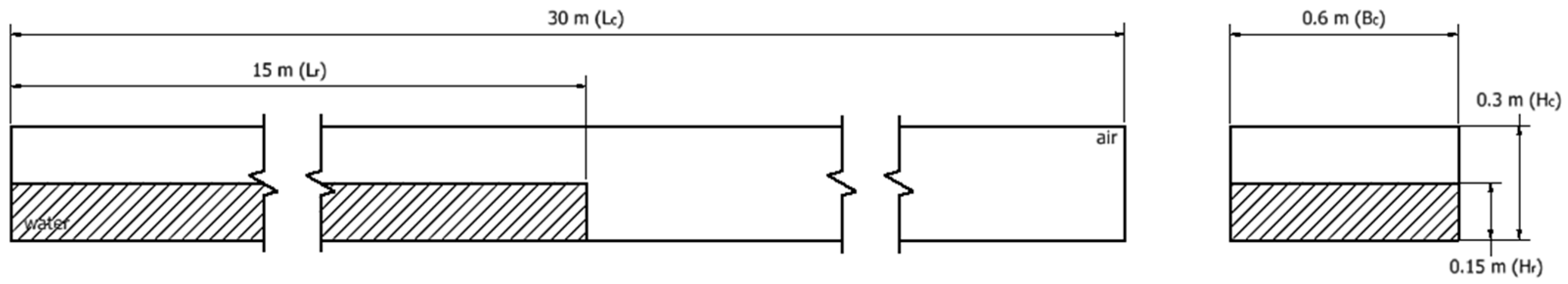
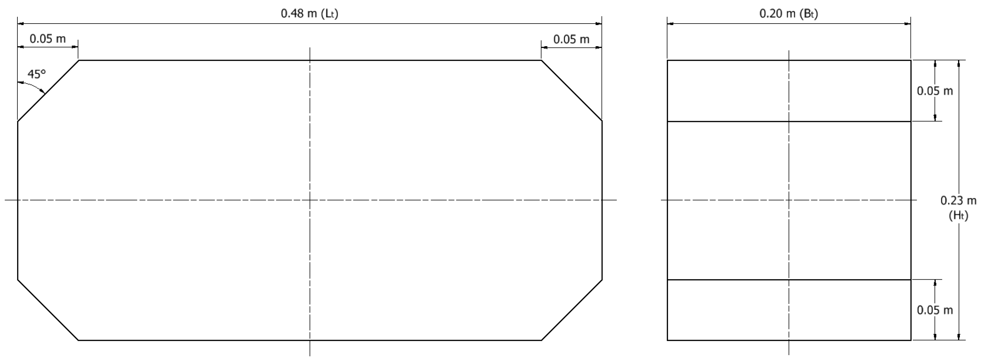
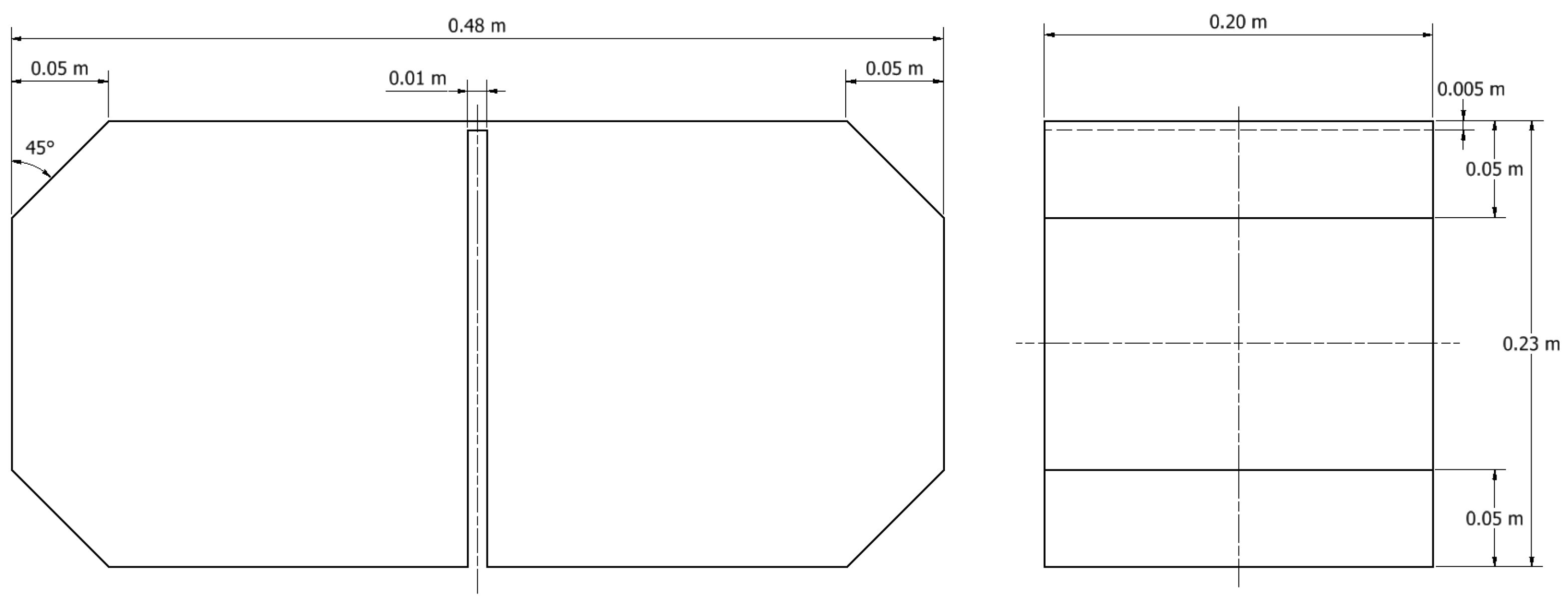
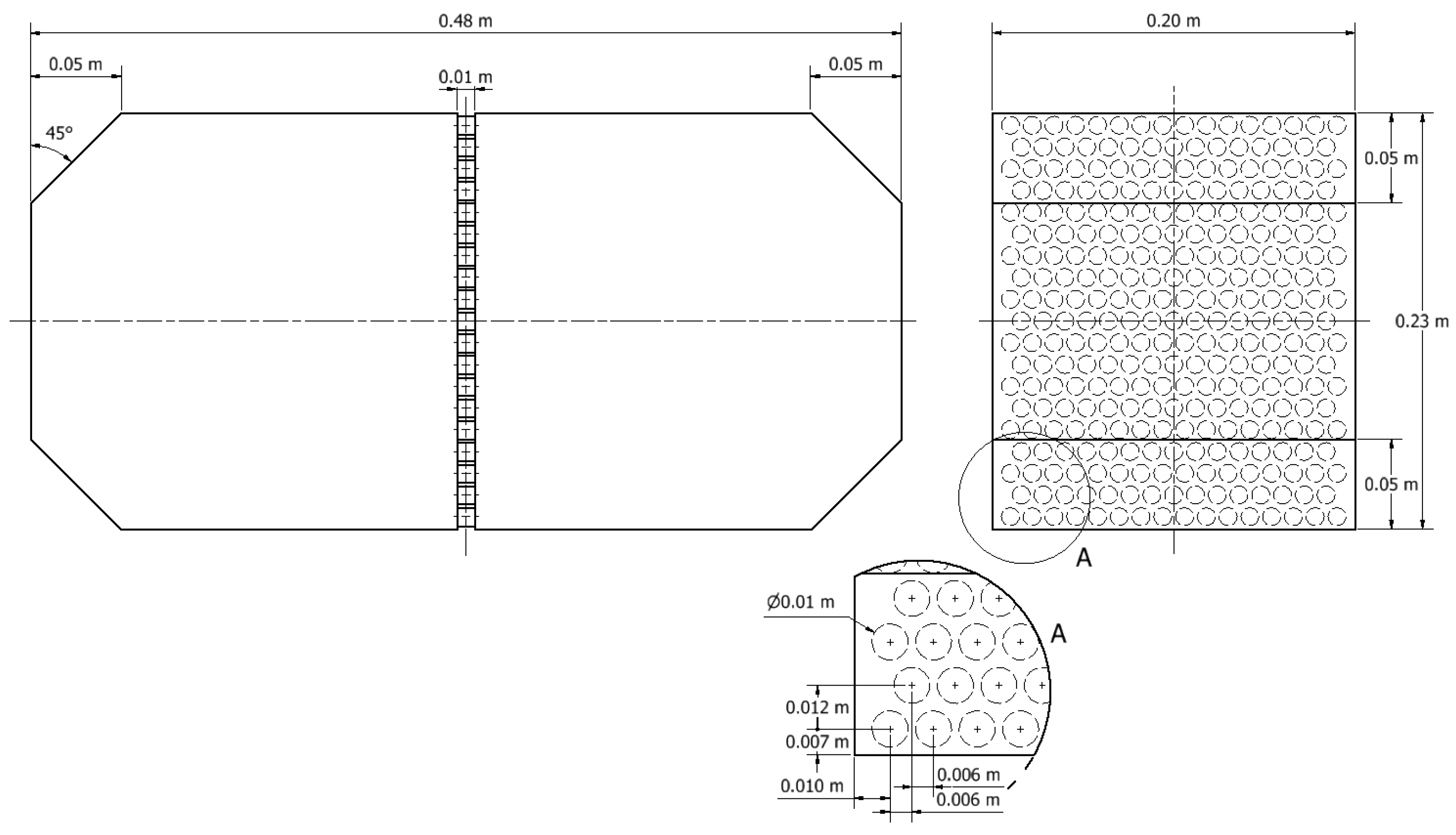
2.1. Physical Setups
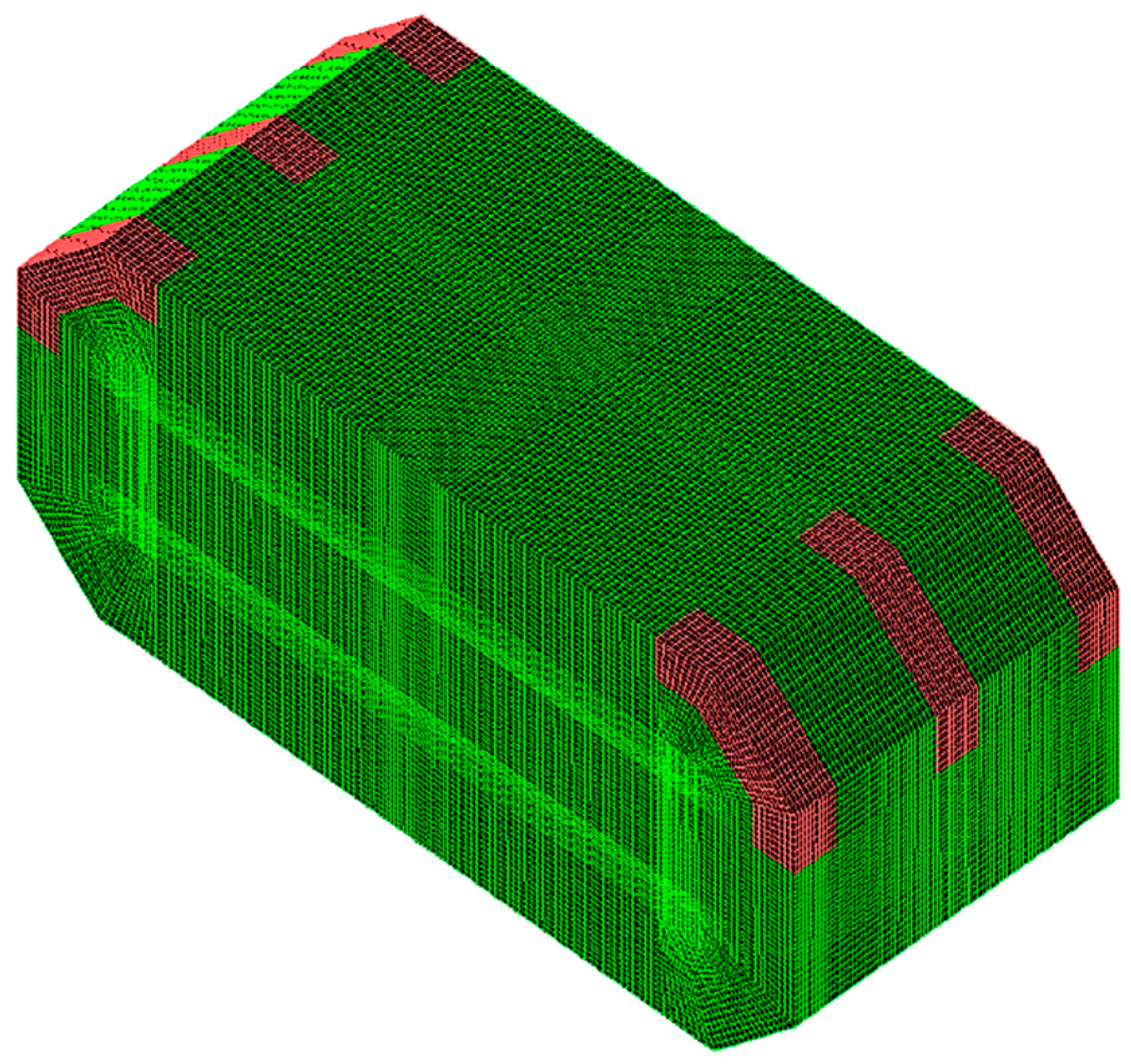
2.2. Computational Setup
3. Numerical Model Characterisation
3.1. Physical Modelling
3.2. CFD Modelling
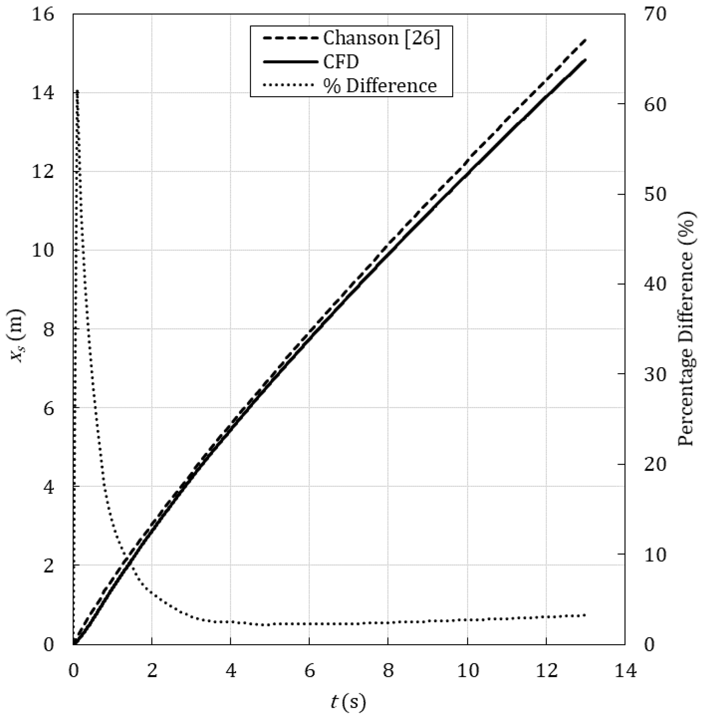
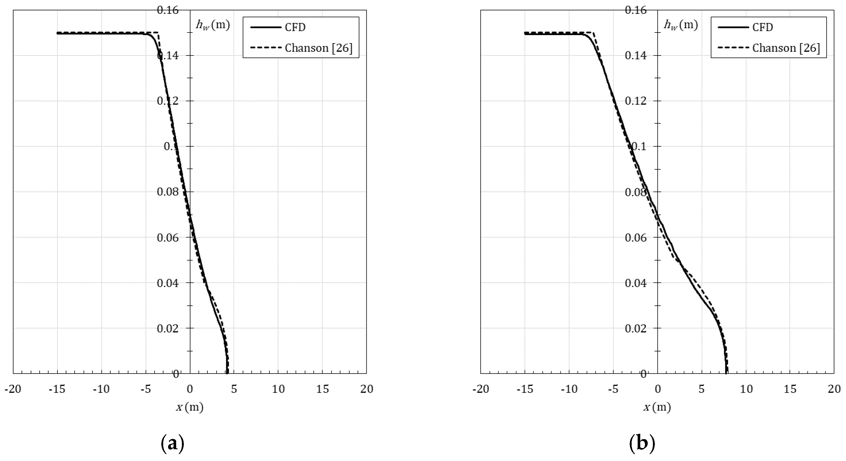
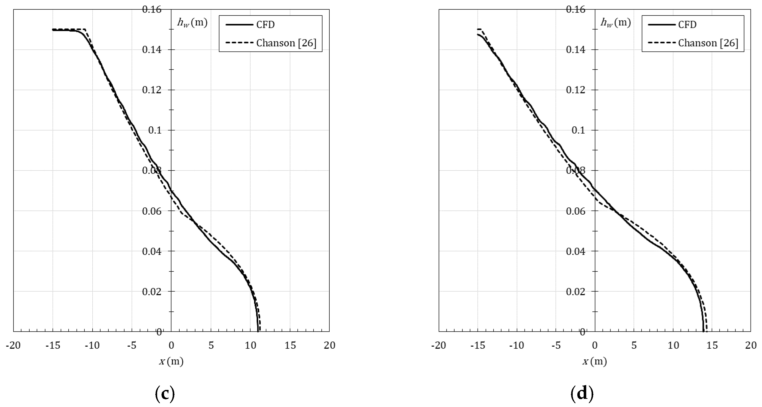
4. Numerical Modelling Validation of a Turbulent Dam-Break Wave
5. Numerical Sloshing Performance of an Open-Bore, Partitioned, and Perforated-Partitioned Tank
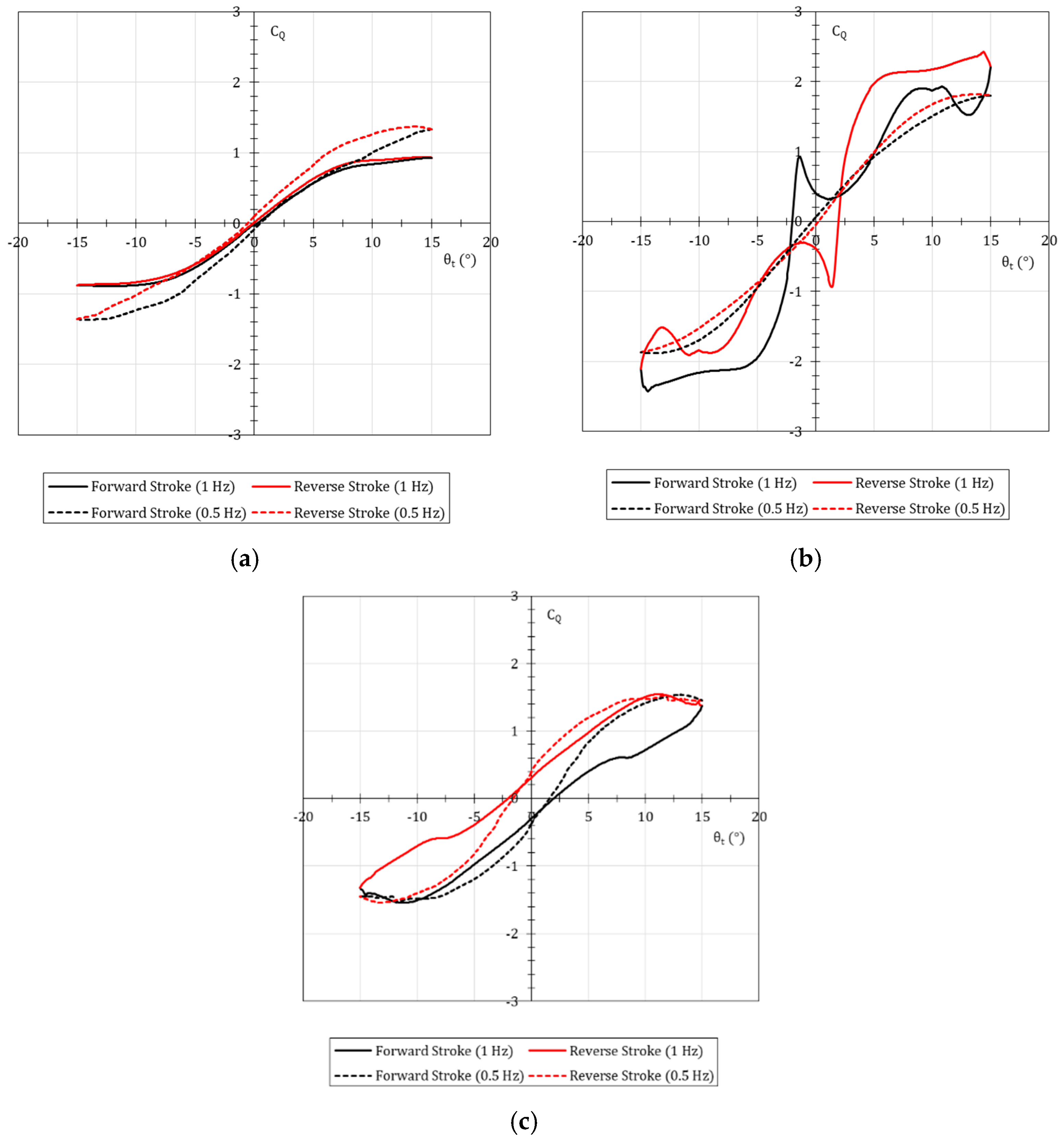
5.1. 20% Fill
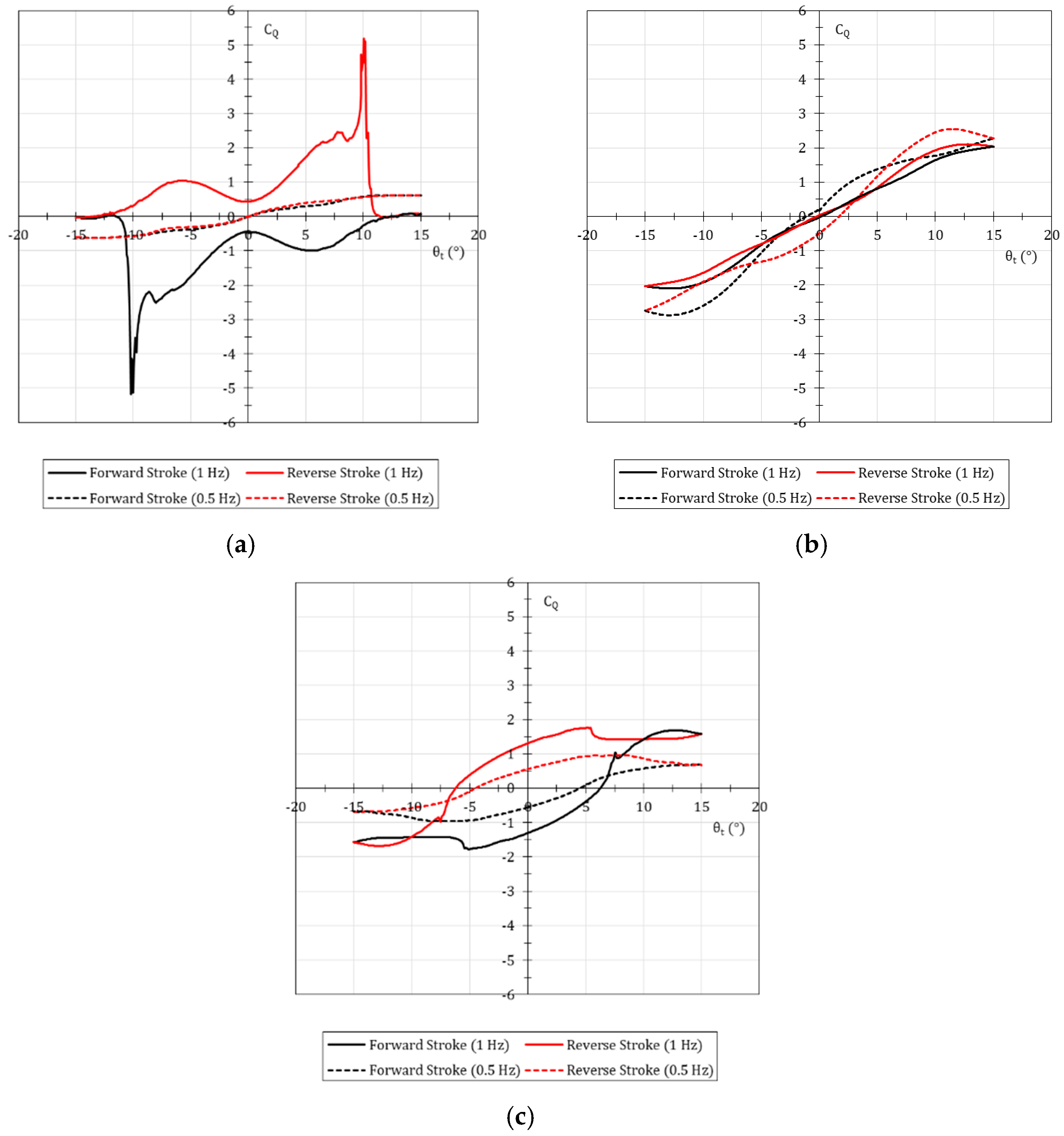
5.2. 40% Fill
5.3. 60% Fill
6. Discussion
7. Conclusions
Author Contributions
Funding
Institutional Review Board Statement
Informed Consent Statement
Data Availability Statement
Conflicts of Interest
Appendix A
References
- Olsen, H. What is Sloshing? In Seminar on Liquid Sloshing; Den Nørske Veritas (DNV): Hovik, Norway, 1976. [Google Scholar]
- Det Nørske Veritas (DNV). DNVGL-CG-0158 Sloshing Analysis of LNG Membrane Tanks; Technical Report; Den Nørske Veritas (DNV): Hovik, Norway, 2016. [Google Scholar]
- Türk Loydu. S.P 01/20 Guidelines for the Assessment of Sloshing Impact Loads. Technical Report. 2020. Available online: https://turkloydu.org/pdf-files/teknik-sirkulerler/tekne/S-P-01-20.pdf (accessed on 18 January 2022).
- Budiansky, B. Sloshing of Liquids in Circular Canals and Spherical Tanks. J. Aero/Space Sci. 1960, 27, 161–173. [Google Scholar] [CrossRef]
- Abramson, H. The Dynamic Behavior of Liquids in Moving Containers, with Applications to Space Vehicle Technology; Technical Report; National Aeronautics and Space Administration (NASA): Washington, DC, USA, 1966. [Google Scholar]
- Slibar, A.; Troger, H. The Steady State Behaviour of Tank Trailer System carrying Rigid or Liquid Cargo. Veh. Syst. Dyn. 1977, 6, 167–169. [Google Scholar] [CrossRef]
- Ranganathan, R. Rollover Threshold of Partially Filled Tank Vehicles with Arbitrary Tank Geometry. J. Automot. Eng. 1993, 207, 241–244. [Google Scholar] [CrossRef]
- Salem, M.I.; Mucino, V.H.; Saunders, E.; Gautam, M.; Lozano-Guzman, A. Lateral sloshing in partially filled elliptical tanker trucks using a trammel pendulum. Int. J. Heavy Veh. Syst. 2009, 16, 207–224. [Google Scholar] [CrossRef]
- Gabl, R.; Davey, T.; Ingram, D.M. Roll Motion of a Water Filled Floating Cylinder—Additional Experimental Verification. Water 2020, 12, 2219. [Google Scholar] [CrossRef]
- Celebi, M.S.; Akyildiz, H. Nonlinear modeling of liquid sloshing in a moving rectangular tank. Ocean Eng. 2002, 29, 1527–1553. [Google Scholar] [CrossRef]
- Akyildiz, H. A numerical study of the effects of the vertical baffle on liquid sloshing in two-dimensional rectangular tank. J. Sound Vib. 2012, 331, 41–52. [Google Scholar] [CrossRef]
- He, T.; Feng, D.; Liu, L.; Wang, X.; Jiang, H. CFD Simulation and Experimental Study on Coupled Motion Response of Ship with Tank in Beam Waves. J. Mar. Sci. Eng. 2022, 10, 113. [Google Scholar] [CrossRef]
- Bulian, G.; Botia-Vera, E.; Mas-Soler, J.; Souto-Iglesias, A.; Castellana, F. Repeatability and Practical Ergodicity of 2D Sloshing Experiments. In Proceedings of the Twenty-Second International Offshore and Polar Engineering Conference, Rhodes, Greece, 17–22 June 2012. [Google Scholar]
- Thiagarajan, K.P.; Rakshit, D.; Repalle, N. The air–water sloshing problem: Fundamental analysis and parametric studies on excitation and fill levels. Ocean Eng. 2011, 38, 498–508. [Google Scholar] [CrossRef]
- Tao, K.; Zhou, X.; Ren, H. A Novel Improved Coupled Dynamic Solid Boundary Treatment for 2D Fluid Sloshing Simulation. J. Mar. Sci. Eng. 2021, 9, 1395. [Google Scholar] [CrossRef]
- Jiang, H.; You, Y.; Hu, Z.; Zheng, X.; Ma, Q. Comparative Study on Violent Sloshing with Water Jet Flows by Using the ISPH Method. Water 2019, 11, 2590. [Google Scholar] [CrossRef] [Green Version]
- Trimulyono, A.; Hashimoto, H.; Matsuda, A. Experimental Validation of Single- and Two-Phase Smoothed Particle Hydrodynamics on Sloshing in a Prismatic Tank. J. Mar. Sci. Eng. 2019, 7, 247. [Google Scholar] [CrossRef] [Green Version]
- Liu, D.; Lin, P. Three-dimensional liquid sloshing in a tank with baffles. Ocean Eng. 2009, 36, 202–212. [Google Scholar] [CrossRef]
- Jung, J.H.; Yoon, H.S.; Lee, C.Y.; Shin, S.C. Effect of the vertical baffle height on the liquid sloshing in a three-dimensional rectangular tank. Ocean Eng. 2009, 44, 79–89. [Google Scholar] [CrossRef]
- Yu, Y.-M.; Ma, N.; Fan, S.-M.; Gu, X.-C. Experimental and numerical studies on sloshing in a membrane-type LNG tank with two floating plates. Ocean Eng. 2017, 129, 217–227. [Google Scholar] [CrossRef]
- Lin, L.; Jiang, S.; Zhao, M.; Tang, G. Two-dimensional viscous numerical simulation of liquid sloshing in rectangular tank with/without baffles and comparison with potential flow solutions. Ocean Eng. 2015, 108, 662–677. [Google Scholar]
- Molin, B. Hydrodynamics Modeling of Perforated Structures. Appl. Ocean Res. 2011, 33, 1–11. [Google Scholar] [CrossRef]
- Faltisen, O.M.; Firoozkoohi, R.; Timokha, A.N. Steady-State Liquid Sloshing in a Rectangular Tank with a Slat-Type Screen in the Middle: Quasilinear Modal Analysis and Experiments. Phys. Fluids 2011, 23, 042101. [Google Scholar] [CrossRef] [Green Version]
- Molin, B.; Remy, F. Experimental and Numerical Study of the Sloshing Motion in a Rectangular Tank with a Perforated Screen. J. Fluids Struct. 2013, 43, 463–480. [Google Scholar] [CrossRef]
- Jin, H.; Liu, Y.; Li, H.-J. Experimental Study on Sloshing in a Tank with an Inner Horizontal Perforated Plate. Ocean Eng. 2014, 82, 75–84. [Google Scholar] [CrossRef]
- Chanson, H. Application of the method of characteristics to the dam break wave problem. J. Hydraul. Res. 2009, 47, 41–49. [Google Scholar] [CrossRef] [Green Version]
- Ship Structure Committee (SSC). SSC-336 Liquid Sloshing in Cargo Tanks; Technical Report; Ship Structure Committee: Washington, DC, USA, 1990. [Google Scholar]
- ANSYS Inc. FLUENT User’s Guide, 5th ed.; ANSYS Inc.: Lebanon, NH, USA, 1998. [Google Scholar]
- Seakeeping Committee of the 28th ITTC. Recommended Procedures and Guidelines: Sloshing Model Tests. Technical Report. 2017. Available online: https://www.ittc.info/media/8111/75-02-07-027.pdf (accessed on 18 January 2022).
- Resistance Committee of the 28th ITTC. Recommended Procedures and Guidelines: Uncertainty Analysis in CFD Verification and Validation Methodology and Procedures. Technical Report. 2017. Available online: https://www.ittc.info/media/8153/75-03-01-01.pdf (accessed on 18 January 2022).


| Cell Number | %difference | ||||
|---|---|---|---|---|---|
| 669,600 | 1.247 | 14.83 | 1.85 | 0.270 | 0.626 |
| 536,970 | 1.277 | 14.56 | 3.04 | 0.431 | |
| 420,500 | 14.13 |
| Cell Number | %difference | ||||
|---|---|---|---|---|---|
| 1,008,640 | 1.215 | 3.93 | 2.80 | 0.111 | 0.781 |
| 830,160 | 1.197 | 3.82 | 4.97 | 0.141 | |
| 693,530 | 3.63 |
Publisher’s Note: MDPI stays neutral with regard to jurisdictional claims in published maps and institutional affiliations. |
© 2022 by the authors. Licensee MDPI, Basel, Switzerland. This article is an open access article distributed under the terms and conditions of the Creative Commons Attribution (CC BY) license (https://creativecommons.org/licenses/by/4.0/).
Share and Cite
Borg, M.G.; DeMarco Muscat-Fenech, C.; Tezdogan, T.; Sant, T.; Mizzi, S.; Demirel, Y.K. A Numerical Analysis of Dynamic Slosh Dampening Utilising Perforated Partitions in Partially-Filled Rectangular Tanks. J. Mar. Sci. Eng. 2022, 10, 254. https://doi.org/10.3390/jmse10020254
Borg MG, DeMarco Muscat-Fenech C, Tezdogan T, Sant T, Mizzi S, Demirel YK. A Numerical Analysis of Dynamic Slosh Dampening Utilising Perforated Partitions in Partially-Filled Rectangular Tanks. Journal of Marine Science and Engineering. 2022; 10(2):254. https://doi.org/10.3390/jmse10020254
Chicago/Turabian StyleBorg, Mitchell G., Claire DeMarco Muscat-Fenech, Tahsin Tezdogan, Tonio Sant, Simon Mizzi, and Yigit Kemal Demirel. 2022. "A Numerical Analysis of Dynamic Slosh Dampening Utilising Perforated Partitions in Partially-Filled Rectangular Tanks" Journal of Marine Science and Engineering 10, no. 2: 254. https://doi.org/10.3390/jmse10020254