1. Introduction
In materials science, research has been often focused on nano and microlevel material structures that form a material at a larger scale. In recent years, with increased cost and environmental burdens, and sometimes higher functional requirements of products, new sustainable material structures such as lightweight structures are becoming critical to industry. However, in the past years, the innovation of new material structures still stays at traditional lightweight structures, such as lattice and honeycomb structures. Bioinspired design has been widely used in design due to its innovative learnings from nature, which have already provided a solution [
1]. However, these bioinspired structures can be extremely complex, making them difficult to manufacture [
2]. Along with the complexity of the design, other manufacturing constraints and design specifications need to be accounted for. For example, a specific, naturally occurring structure may provide the manufacturer with a designed property or characteristic but may not fulfill sustainability requirements, strength requirements, and even cost requirements [
3]. Topology optimization is a method that utilizes mathematical tools in order to optimize material distribution [
3]. This process can be used to fulfill these requirements. Natural structures, however, are usually created within certain physical conditions (e.g., material) or external environments (e.g., temperature) but offer inspiration for novel solutions. The natural system is studied to understand the structure and how it can be adapted to meet the requirement of a design application. This can be performed through topology optimization to analyze the material structure requirements and constraints [
4]. For example, removing unneeded material from a bioinspired structure will produce a lightweight and more sustainable structure with a structural strength serving the same function as the original structure [
5]. However, the topology optimized structures are usually not standard geometries, thus causing manufacturing difficulties [
6]. One effective way to produce these extremely complex structures when considering geometry accuracies is through additive manufacturing (AM) [
7]. AM is a process that uses computer aided design models to generate a physical material structure by dividing the models into many layers and stacking the layers onto one another [
7]. This allows for the material production of any shape or structure imaginable, making additive manufacturing the most optimal method for producing bioinspired structures that have undergone topology optimization [
7]. Integrating manufacturing considerations in bioinspired design and topology optimization, however, becomes a challenge when the manufacturing processes do not always produce the ideal quality as in the original design [
8]. Meanwhile, the design process becomes a more complex problem when accounted for numerous factors and constraints [
9]. Systems thinking is an approach to understand and analyze a problem as a complex whole, and it solves problems with holistic views [
10]. Therefore, a systematic method is required to assist design engineers to use topology optimization in a sustainable bioinspired design process of material structures.
Despite the lack of research surrounding the effect that all three aspects have on one another, there has been much research integrating two of the three during material structure design and material structure. Studies indicate that topology optimization gives promising results in terms of mass production optimization, and additive manufacturing can be used to remove many design constraints. This reduction in mass creates a lightweight design that uses significantly less material and ultimately reduces energy consumption, production time, and material production costs [
3]. In addition, topology optimization can increase in max allowable speed, and overall performance of the AM process [
11]. In the research of interpreting these topology results, a study on skeleton design found that converting the topology optimization results to a stereolithography (STL) file allows for a skeleton of the shape to be extracted. Extracting the skeleton allows for its shape, as well as its characteristics, to be preserved [
12]. Although AM faces challenges such as efficiency [
13], AM appears to be the only realistic way to achieve many of the complex structures generated through topology optimization [
14]. Using both topology optimization and AM in tandem serves as the best procedure for producing parts that meet mechanical requirements while using as little material as required [
15].
Similarly, research found that AM made it significantly easier to produce complex bioinspired designs that are still functional [
5]. Examples of such applications are numerous, such as scaffolding [
16], infill patterns [
17], gears [
18], microtiter plate [
1], and soft materials, machines, robots, and haptic interfaces [
19]. These studies found that further optimizing the biologically inspired designs (e.g., scaffolding) increased the mechanical stiffness while maintaining the porosity distribution at a level that provided a durable and lightweight material structure [
16]. Similar to topology optimized structures, however, bioinspired designs themselves can be complex, creating many manufacturing issues that can only be addressed through the use of AM [
20]. Not only can AM be used to produce these extremely complex structures, but it can also help in achieving a level of detail similar to the original natural structure and, in many cases, even down to the microscopic level [
21]. Research has shown how AM can be used to produce bioinspired structures that exhibit a high fracture resistance and have increased mechanical performance when compared to similar structures [
22].
Studies have also been carried out that observe the relationship between bioinspired design and topology optimization itself. It has been found that bioinspired patterns can be used as a form of topology optimization. This topology has been used to optimize machining equipment, and results showed an increase in stiffness and sustainability [
23]. This increase in stiffness is beneficial to material structure that have load bearing applications. For example, a lightweight lattice structure was designed based on of cuttlefish bones and topology optimization was used to maximize structural stiffness [
24]. Along with increasing stiffness and sustainability, topology optimization can also be used on bioinspired designs to decrease the weight of the material structure [
5,
25]. Using topology optimization to decrease the weight of a material structure has various applications that are primarily found in the aerospace and automotive industries. When considering the aerospace industry, topology optimization can be used to reduce the weight of integral structural systems without sacrificing any aerodynamic properties [
26].
As well as observing the relationships between all three of the aforementioned topics, this research will also utilize a systems thinking methodology. Systems thinking aids with understanding most ecological concepts [
27]. For example, the complexity of biophysical mass and energy transformation systems can be understood with a systems analysis approach using dynamic modeling. Having an in depth understanding of systems thinking allows design engineers to achieve the highest level of bioinspired design and emulation of the whole ecosystem, which allows for bioinspired designs to fit seamlessly into the biosphere [
28]. The environment itself also provides many examples of systems thinking, where the connection between biological systems and the environment can be compared to manmade systems [
29]. The concept of bioinspired design itself is ultimately a result of living systems, as well as holistic thinking [
30,
31]. This is because the natural structures being used for inspiration have evolved to become more suitable to the constantly changing environment around them [
30]. These evolutions can directly be related to a systems methodology, where many different variables have an effect on a specific structure to create changes to that structure [
30].
There are many industrial applications of bioinspired material structures. Lightweight structures have been a popular application in various studies. Lattice, honeycomb, bone [
17], and butterflies’ wings [
32] can be used to design materials or products when strength-load ratio is particularly important in industries, such as automotive and aerospace. Bird beak, fish skin, luffa, and horseshoe can be used in energy absorption applications, such as transportation, nuclear reactors, and civil engineering [
33]. In addition, structure materials, such as bamboo and compact bone structures, can be used in orthopedic implants and high efficiency industrial cutting and drilling tools [
34].
Despite the research conducted, a gap still remains that this research is looking to answer: how the synergy of bioinspired design, topology optimization, AM, and systems thinking can be used to produce a sustainable material structure. Along with observing the relationships between these topics, this research seeks ways to further optimize bioinspired structures using topology optimization for different conditions rather than the environment it was originally created in. Therefore, the goal of this research is to propose a topology-based bioinspired design method using systems thinking principles and incorporate AM considerations in the material structure design. Specific objectives include:
Integrate systems thinking principles into bioinspired design and topology optimization.
Use a case study to demonstrate the application of the proposed method.
Develop bioinspired designs for lightweight structure infill patterns.
This study will benefit the materials science community by providing materials engineers with a systems thinking framework to assist the planning, ideation, embodiment, improvement, and validation processes for bioinspired design of lightweight structures for the additive manufacturing process.
2. Methodology
Figure 1 shows the proposed framework that incorporates systems thinking, bioinspired design, and topology optimization. The framework is used to produce a topology optimized bioinspired material structure design. The words accentuated in red indicate the elements of the methodology that are key concepts from the systems thinking approach.
Systems thinking is an approach and philosophy that aims to gain a holistic understanding of a problem and provide a comprehensive solution [
35]. It characterizes a complex problem as a system composed of interconnected components, the behavior of which determines the overall performance of the system [
36,
37]. It is desired that early in the design process, materials structure designers should capture all relevant aspects of the system to be designed. Several key characteristics of design need to be considered, including boundary, understanding, uncertainty, and delays.
This methodology starts by setting a boundary for the research project and only focusing on elements that fall within that boundary. Once a boundary has been set, material structure requirements (Step 1) are then identified. These requirements may differ between material structures and are determined based on the intended use for that structure. Along with material structure requirements, design space is also determined for the design of the structure. Design space is primarily determined based on material structure requirements, but three concepts can be used to determine whether a design is acceptable. These concepts include questions, options, and criteria [
38]. Questions are asked to identify any issues that may be created as a result of the design. Options are used to address those questions and provide possible solutions. Finally, criteria are used to compare the different options and evaluate which ones are most effective at addressing the questions [
38]. Design space may also be influenced by historical data and user feedback.
After the material structure requirements have been identified and the design space has been determined, a bioinspired concept (Step 2) is then selected. The selection of the bioinspired concept is based on the function of the material structure, and also on having an understanding of the benefits that the specific concept provides in nature. Biological systems can be understood using four categories: physiology (vital functions), morphology (physical form), behavior (response to external stimuli), and strategy (behavior in achieving goals) [
39]. Common methods for bioinspired concept selection include Bio Theory of Inventive Problem Solving (BioTRIZ), functional modeling, and natural language analysis, structure-function patterns, and four-box approach. BioTRIZ is a design method that aims to solve a bioinspired design problem by defining a pair of conflicting parameters and finding solutions that were evolved in a natural system [
40]. Functional modeling is a qualitative method that abstracts the biological information so it can be applied to engineering problems. There are three main approaches to functional modeling. Flow-based modeling is a method that focuses on the functionality of a system [
41]. It identifies the biological system that is most applicable to the design and consistently isolates and models the components of the nature system by defining the category and scale of the model.
Structure-behavior-function (SBF) modeling generates separate models that are interconnected to understand components, states, and state transitions [
42]. Increasing in detail, the SAPPhIRE model provides seven constructs to capture the functionality of biological systems by providing causal descriptions of the systems [
43]. Natural language analysis is used to analyze biology sources, which are written using less jargon, during inspiration search for biological systems that are relevant using engineering-oriented terms [
44]. Structure-function patterns are a set of system level patterns (e.g., repeated protrusions—attach) to build analogies between observed solutions in nature and problems yet to be solved. The four-box approach is a problem formulation and analogy evaluation tool that describes function, operational environment, specifications, and performance criteria of systems [
45]. These methods have been very useful in bioinspired design and have been used as guidelines in general engineering design.
The selected biological structure should also have properties that will help the material structure to achieve its goals more easily. With the material structure requirements identified and bioinspired concept selected, material structure design (Step 3) can now be started. When designing the material structure, it is important that the bioinspired concept can easily be incorporated without forfeiting any of the material structure requirements. It is also important to consider the use of the material structure during the design phase. Once the design is complete it will undergo a finite element analysis (FEA) or fatigue analysis (Step 4). Both the FEA and fatigue analysis observe how the material structure will react to certain real-world forces, such as heat, vibration, stress, and other physical forces. This research will primarily focus on the stress, displacement, and strain generated by the force applied to the material structure. From the results generated by the FEA, it can be seen whether that design meets structural standards for its intended use. If the design does not meet these standards, the bioinspired concept should be reevaluated, and the structure should be redesigned. If the structural standards are met, then the design will go through the process of topology optimization (Step 5). Before topology optimization is conducted, sustainability standards and manufacturing constraints need to be taken into consideration. These sustainability standards are determined when the boundaries for the project are set. Topology optimization is conducted in order to determine the most optimal way to distribute material in the structure. This distribution of material is determined by a force that is applied to the structure. From this force it can be seen which areas of the structure are most impacted by the force. Those areas that are under little to no stress as a result of the force, can be removed without impacting the properties of the structure. Traditionally, topology optimization is conducted using algorithms that generate a mesh of the structure in either a 2D grid or a set of 3D cubes. Fusion 360, which was used for topology optimization in this case study, uses a Solid Isotropic Material Penalization (SIMP) algorithm [
46]. The method predicts an optimal material distribution with a given design space for given load cases, boundary conditions, manufacturing constraints, and performance requirements [
47,
48]. This algorithm uses X
e to show density of the structure. Where X
e = 0 indicates a void and X
e = 1 indicates present material.
After topology is conducted the structure goes through prototyping and material structure testing in functional environments (Step 6). If the structure fails any testing or prototyping, a structure redesign or a concept reevaluation is required. However, these redesigns and reevaluations can be time consuming and create many delays in the system. The concept reevaluation goes back to the bioinspired concept selection and revisits candidate concepts that could achieve the same goal. Along with delays, there are also some uncertainties that should be considered when following this methodology. These uncertainties are embedded in every aspect of the design process. For example, in topology optimization there is uncertainty in the environment constraint definition in the modeling process versus the real material structure processing environment. Similarly, in the prototyping stage, there is quality inconsistency in manufactured structures and the tested 3D model. In addition, design engineers should also consider the potential delays in concept reevaluation, manufacturing prototypes, and problem identification. These delays usually hinder the design process and cause difficulties in completing the design.
The developed designs will also be evaluated on multiple sustainability metrics, including additive manufacturing printing time, production cost, and manufacturing quality. The printing time largely depends on complexity of the design. More complexity adds more moves of printing heads and supporting materials. However, compared to traditional machining and manufacturing processes, complex geometries can be extremely difficult to make and the additive manufacturing process can generate finer structure details with these complex structures. Therefore, processing costs can be saved. However, economy of scale needs to be applied because, currently, 3D printers, especially metal 3D printers, are a high-cost investment. Lastly, environmental impact of manufacturing the bioinspired structures can be assessed based on the material use and energy consumption involved in the manufacturing.
This proposed framework provides a systematic procedure and methodology to bioinspired design and topology optimization for material structure designers. The developed methodology is based on the systems thinking principles which are desired for designers in the process of understanding the problem, choosing bioinspired concepts, and applying the concept to the material structure design. These principles should be embedded in the entire life cycle of the design, so the designs take a holistic approach to oversee challenges, problems, and the design process.
3. Case Study
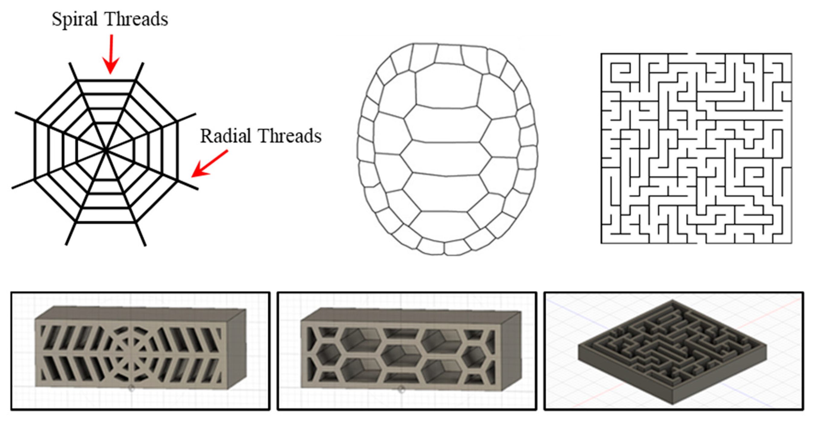
The purpose of this case study is to use the proposed framework to design lightweight infill patterns with topology optimization as a way to improve the functionality and sustainability of the structure. These prototypes were designed based on specific material structure requirements. It was required that these prototypes use the minimum amount of material required without forfeiting any load-bearing functionality. Each prototype was also assumed to be a 3” × 3” × 1” shape with a hollow interior that would be filled by different biological and other complex structures. The bioinspired structures used for the infill of the prototypes were selected considering their natural properties. Two different structures were observed, a spiderweb and a turtle shell pattern. In addition, a maze structure was also identified to study its functionality and sustainability compared to the other two biological structures. They were all selected based on the specific properties they provide in nature and how well those properties fit the material structure requirement. The spiderweb was used for bioinspiration because it excels at equal force distribution. This is attributed to the general shape and layout of the web. Every orb web is made up of a connection of both spiral threads and radial threads, which can be seen below in
Figure 2. In nature, spiders can increase the number of spiral threads to create a denser web, while also changing the number of radial threads to reduce the cost of making the web without altering its damage tolerance. Even if a spiral or radial thread is completely damaged the force that was acting on the thread is equally distributed throughout the web to maintain its high damage tolerance. These orb web properties serve as an ideal bioinspired concept for a structure that is intended to withstand large amounts of force. Mimicking a spiderweb would also allow the structure to equally redistribute force when a section of the web is broken or damaged.
The turtle shell pattern was used to mimic the strength and load-bearing properties that can be seen exhibited by the structure in nature. Naturally, the turtle shell is used for protection and has been used as bioinspiration for many structures, such as helmets and body armors. However, this research will observe how the pattern formed by the scutes on the top of the shell can be used as a lightweight and strong infill pattern. The turtle shell pattern was designed based on how the scutes, or plates, come together to form the shell itself. This provides the structure with optimal load-bearing capabilities, allowing the structure to withstand large amounts of force [
49]. Naturally, the borders between the plates of the shell are zones of weakness, which is because these areas are typically thinner than the rest of the shell [
50]. However, the design used for this research is an outline of the plates so those thinner areas that are sources of error have been removed.
The final structure observed was designed based on a maze. Unlike the two previous structures which were designed horizontally, the maze structure was designed vertically.
Figure 2 shows all three designed structures and shows that the spiderweb and turtle shell were designed from the back to the front of the structure, while the maze was designed from top to bottom. Having the maze developed in a vertical orientation could be beneficial when applying a force to the top of the structure. The maze used for this structure was designed with tight corridors to avoid any voids that could cause defects when a force is applied. Generally, mazes are generated by using specific algorithms and there are different algorithms for different types of mazes. The most common type of maze is a perfect maze, which contains no loops and allows the user to visit every location by simply following a wall [
51]. It is important to note that maze structure is not a natural structure and identify that this structure is used to study the unnatural special structure compared to bioinspired structures.
After a structure is designed based on its structure requirements and bioinspired concept, it is then subjected to an FEA or fatigue analysis. Although the structures can be universally used in various materials, the material tested in the experiment of this case study was polylactic acid (PLA). These tests observe how the material structure reacts to specific real-world forces and generates data showing the stress, displacement, and strain created by the force applied. Cross sections of these three structures can be seen in
Figure 2. Each structure was designed as a 3” ×3” ×1” block with the internal structure of the blocks being designed based on a naturally occurring structure. The outside surface of the block are six solid walls. Other geometric properties for the final designs can be seen below in
Table 1.
The prototypes were printed with Polylactic Acid (PLA), and Polyvinyl Alcohol (PVA) as dissolving supporting material. A mechanical properties comparison of the two materials is shown in
Table 2. The PVA material used in printing the parts will not affect FEM results as support materials are only used in during printing and they are not shown in finite element models.
These structures were all designed, modeled, and analyzed in SolidWorks. Once a design was finalized, it was then subjected to FEA to further examine the stress, displacement, and strain experienced by each structure due to a given force. As the purpose of this case study is to analyze the general behavior of the structure areas, the focus of analysis is to find the weak and strong spots of the structure, therefore only FEA was conducted in the mechanical analysis. In cases such as when a particular physical material needs to be studied, fatigue analysis and the corresponding stress strain behavior can be analyzed. To conduct this FEA, two geometries of the structure are selected, one geometry will remain fixed and the second geometry will have an applied force. For this study, the bottom face of each structure was set as the fixed geometry, while an external load was applied to the entire top face. Three different load values were analyzed 50,250, and 500 newtons (N). These load values were selected to subject the structure to a small, large, and slightly larger force. The same load values were also used to conduct topology optimization. The values were also chosen to observe if extremely different loads would produce different optimized topologies. From these load values, it can be seen how well each structure handles the load and if that same structure meets specified strength requirements. Along with using SolidWorks to conduct FEA, SolidWorks was also used to produce a sustainability report for each of the three structures individually. The sustainability serves as a method for analyzing the environmental impacts associated with the manufacturing of these structures. For this research, the sustainability assessment will highlight environmental impacts such as carbon footprint, energy consumption, air acidification, water eutrophication, and emission factors.
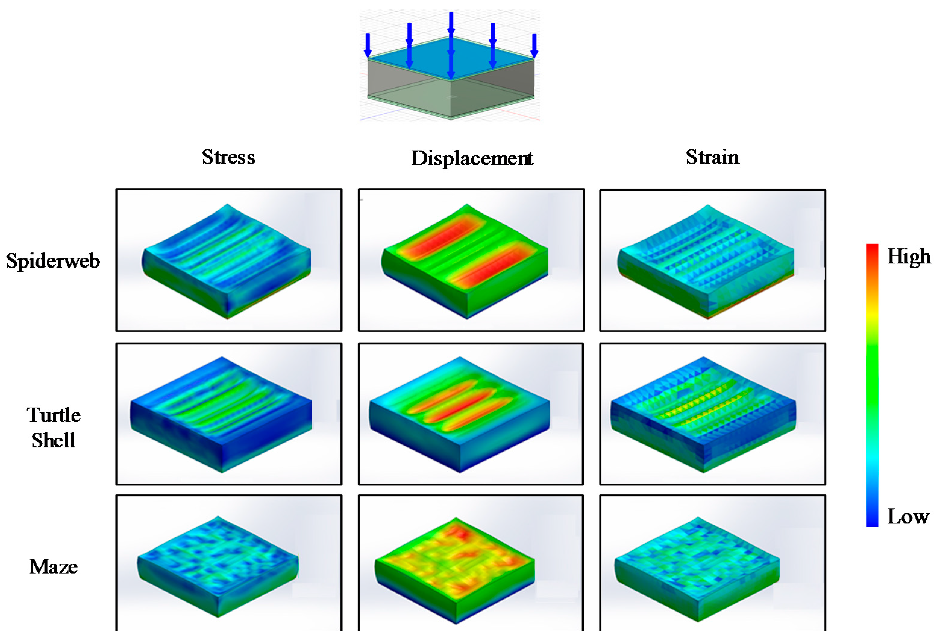
The results from the FEA are presented above, in
Figure 3 and
Table 3, and show how each structure was affected by applied forces. Note that the blocks in the figures represent the actual material structure design which has solid walls in the outside surface and designed geometries inside the block. Distributions of stress, displacement, and strain are shown in
Figure 3, where red indicates positive values (shrinkage) and blue indicates negative values (expansion).
Table 3 shows the absolute values of these variables. For the spiderweb, the areas under the most stress were located towards the center of the structure. This is a result of the force being applied to the top face and other surrounding areas failing due to deformation, causing the stress to be redistributed towards the center. The displacement of the spiderweb occurred in the areas left and right of the center. These areas were displaced the most because, unlike the center and walls of the structure, the material was not densely packed. Those two major displacements happened in the areas of the structure where many voids were present. The strain experienced by the spiderweb was very similar to its stress and for many of the same reasons. The turtle shell structure experienced the most stress around the areas of deformation. Like the spiderweb, stress was redistributed to these areas after sections failed due to deformation. These areas of deformation can most notably be seen through displacement and again, just like the spiderweb, the most displacement was seen on the turtle shell in areas of the structure where many voids were present. The turtle shell also experienced strain very similar to how it experienced stress. However, the maze produced results very different from the spiderweb and turtle shell. Stress for the maze was spread out over the top face, mainly occurring in areas where voids were not present. Compared to the two previous structures, displacement of the maze was more spread out with various areas of deformation. The strain experienced by the maze was also similar to the stress, like the two other structures. These differences when comparing the maze to the spiderweb and turtle shell can be explained by the orientation of the infill structure. The spiderweb and turtle shell infills were designed to run horizontally, which resulted in long voids that led to large amounts of displacement. The maze, however, was designed vertically, which more evenly distributed the force and led to less deformation.
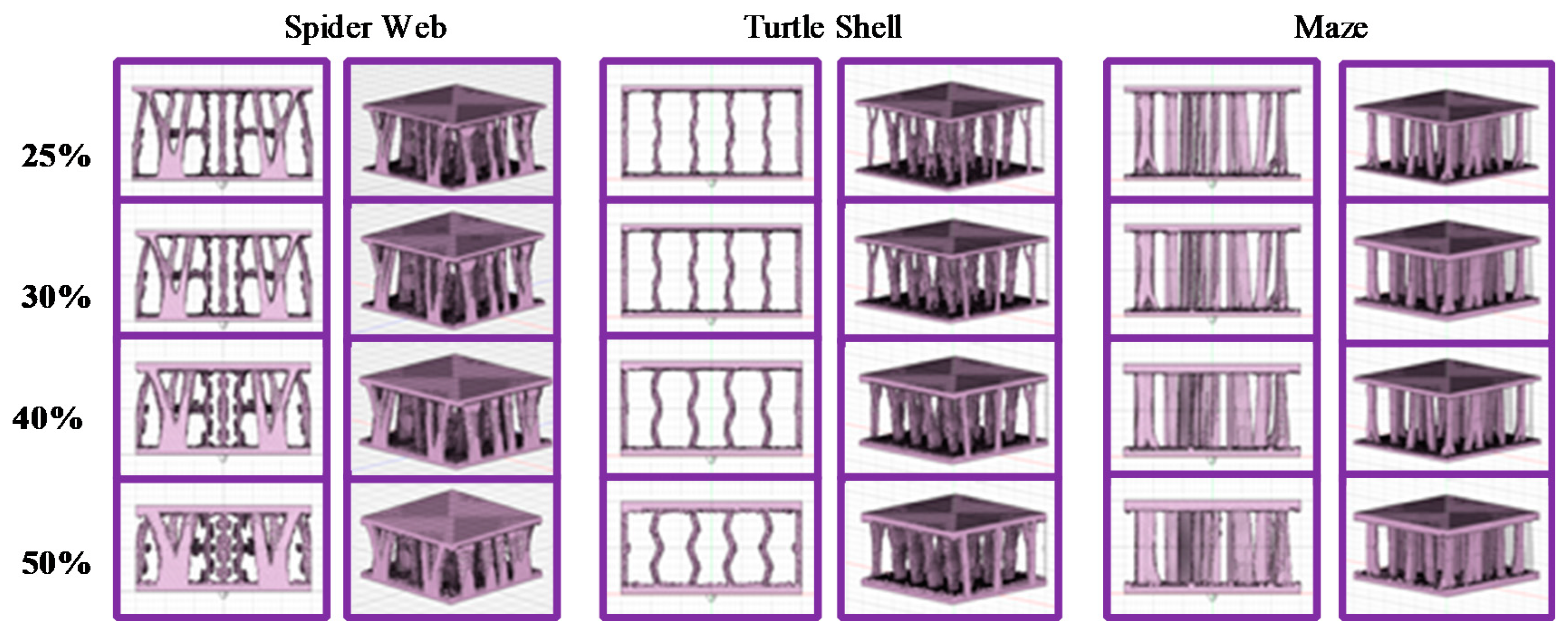
Once structure designs have been finalized and FEA has been conducted, topology optimization can be used to further increase performance and sustainability. Topology optimization analyzes the stress created by an external load on the structure and removes those areas of the structure that are under little to no stress. This process is used to reduce the amount of material used in manufacturing while also maintaining a level of strength similar to the original structure. The reduction of material can also help to reduce production time, production cost, and meet sustainability requirements. However, using topology to optimize a structure greatly increases its complexity, thus creating more manufacturing limitations. These limitations can be addressed using additive manufacturing.
Figure 4 shows the optimized version for all three structures. Fusion 360 topology function was used for conducting topology optimization. The structures were optimized based on a Solid Isotropic Material Penalization (SIMP) algorithm, as described in the methodology section. The optimization begins by setting constraints on the structure, and for all the structures in this research, both the top and bottom faces were set as constraints. When a geometry is set as a constraint, it will remain unchanged and not be affected by the topology optimization. Once the constraints are set, a load is applied to a specific geometry on the structure. This load was applied to the top face for each structure and three different load values were observed on each structure. The load values observed were, 50 N, 250 N, and 500 N, identical to those used in the FEA. With both the constraints and the load selected, a sold mesh of final topology optimized structure is generated. The solid mesh is generated with tetrahedral 3D solid elements. Each element size is 0.43 mm. The number of total elements is 1,831,874. The maximum aspect ratio is 15.503, and the percentage of elements with aspect ratio smaller than 3 is 95.1 while the percentage of elements with aspect ratio bigger than 10 is 0.0599. The generated part structure has a default remaining mass ratio that is 30% of the original structure’s mass, meaning that 70% of material was removed from the original structure. This remaining mass ratio can be changed, and for this research, four different remaining masses were observed, those being 25%, 30%, 40%, and 50%. In total, twelve different topology optimized structures were generated for all three original structures, creating thirty-six total optimized structures.
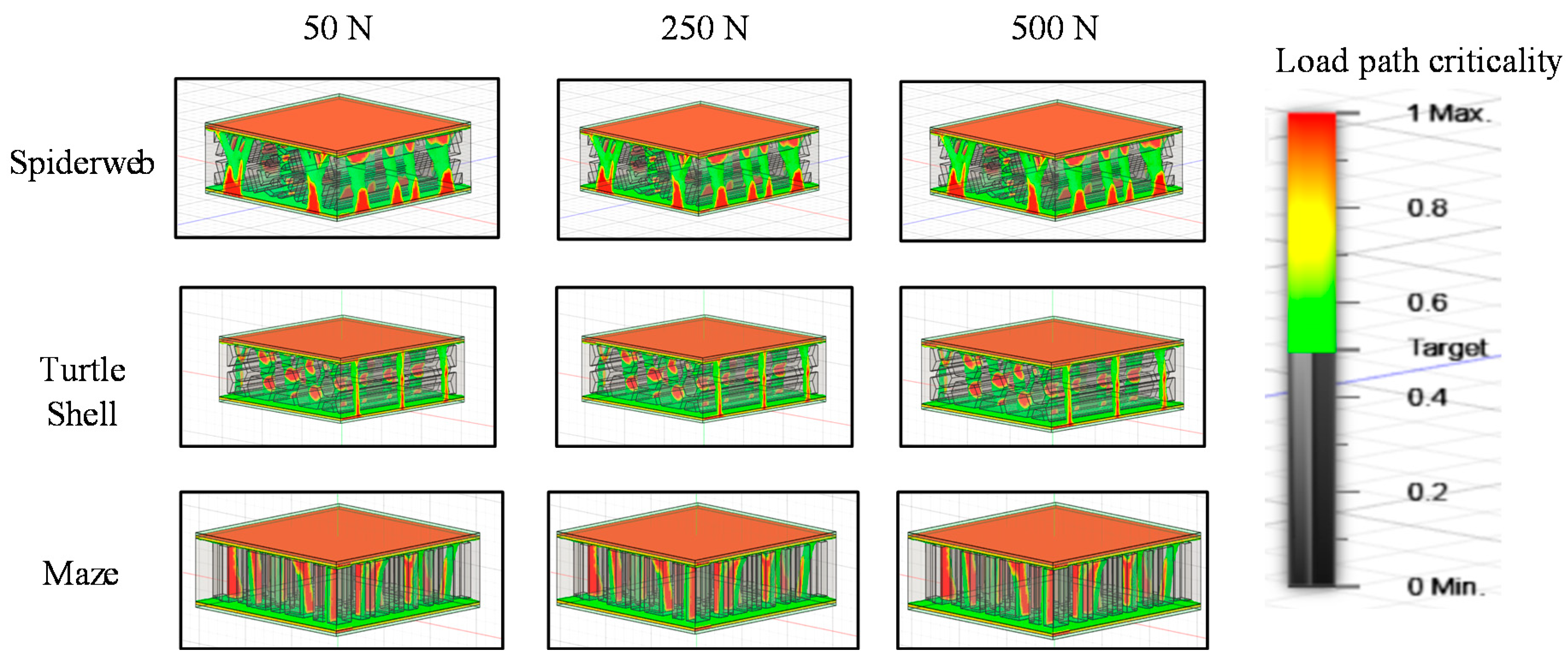
Figure 5 shows the optimized versions of each structure for each force value tested. The colored regions show the load path criticality value, which is a 0 to 1 variable, and represents the region in the model that is critical to resisting the applied load. All the structures displayed in the figure were also all set to have a remaining mass ratio of 30%. From these optimized structures, most of the exterior walls were almost completely removed. This varied depending on the structure, with the maze having all exterior walls removed, the turtle shell having most of its exterior walls removed, and the spiderweb having small areas of wall remaining near the base of the structure. One key finding from these tests was that no matter how large the applied force was, the generated optimized topology always stayed generally the same with little to no changes. Each version of every structure was nearly identical regardless of the force that was applied. This shows that the topology optimized structures were generated primarily from the location of the force rather than the size of the force.
Once topology optimization is conducted for each structure, the optimized variants are saved for printing. For this research, both the optimized and nonoptimized structures were printed using an Ultimaker 3 [
55]. The machine used a 0.25 mm diameter nozzle, and the build volume was 230 × 190 × 200 mm
3. The build speed was 24 mm
3/s. The printer used standard 1.75 mm filament with dual print heads. One head was for PLA and the other head was for the support material, PVA. All parts were put into water to dissolve the PVA material. Thus, all the tested parts were made of PLA. The build speed was less than 24 mm
3/s and the nozzle temperature was between 180–280 °C. The printer maximum power output was 350 W. The structures were printed bottom up, with an infill density of 100% and infill line distance of 0.4 mm, as shown in
Figure 4 and
Figure 5. Because the purpose of testing printed parts is to examine the manufacturing quality and the structure strength, it was tested through compression test.
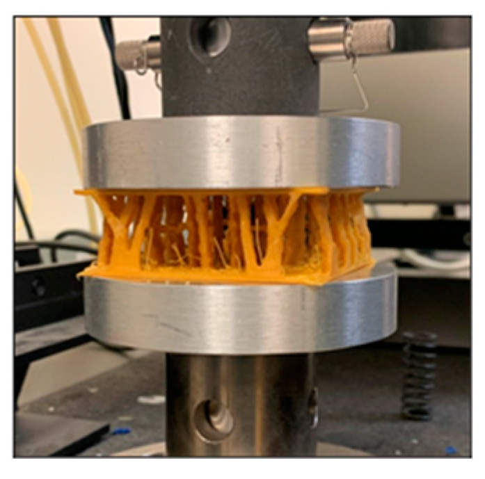
The testing parameters that were selected for the mechanical testing of these bioinspired structures were that of a maximum load of 25,000 N that was not to be exceeded. The platens would move at a speed of 6 mm per minute, and the platens would compress until reaching an extension of 15 mm from the top of the structure. The test proceeded until a value of 25,000 N was met or an extension value of 15 mm was achieved, whichever came first. All compression tests were conducted on a Instron Machine (
Figure 6).
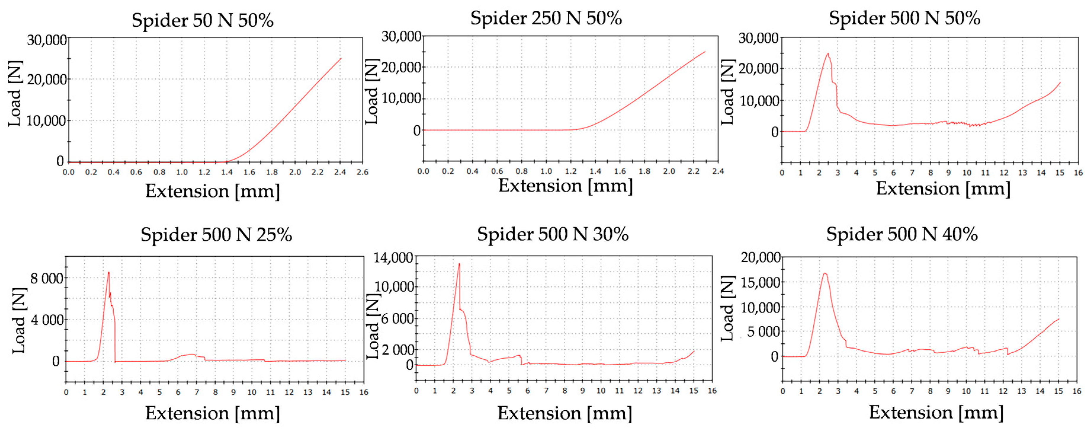
The results for the three different structures vary greatly. The spiderweb structures of the 50% material reduction at load values of 50 N, 250 N, and 500 N behaved similarly (
Figure 7). The 50 N and the 250 N at 50% material left, both exceeded the testing parameters and withstood a force greater to or equal to 25,000 N, resulting in the conclusion of the test. However, the 500 N load value at 50% failed right before the 25,000 N mark and the structure collapsed resulting in the test continuing until the extension of the platens reached 15 mm. Due to inconsistencies in the results of the 50% material remaining at the three different load values, these results did not offer us conclusive findings, or we were unable to identify any patterns within the results. The compression test results for the 500 N load at 25%, 30%, and 40% behaved more closely to what was anticipated. The 25% structure reached a maximum load value of 8500 N at an extension of 2.3 mm before collapsing. The 30% structure reached a maximum load of 13,000 N at an extension of 2.4 mm and the 40% withstood a maximum load of 17,000 N at an extension of 2.4 mm.
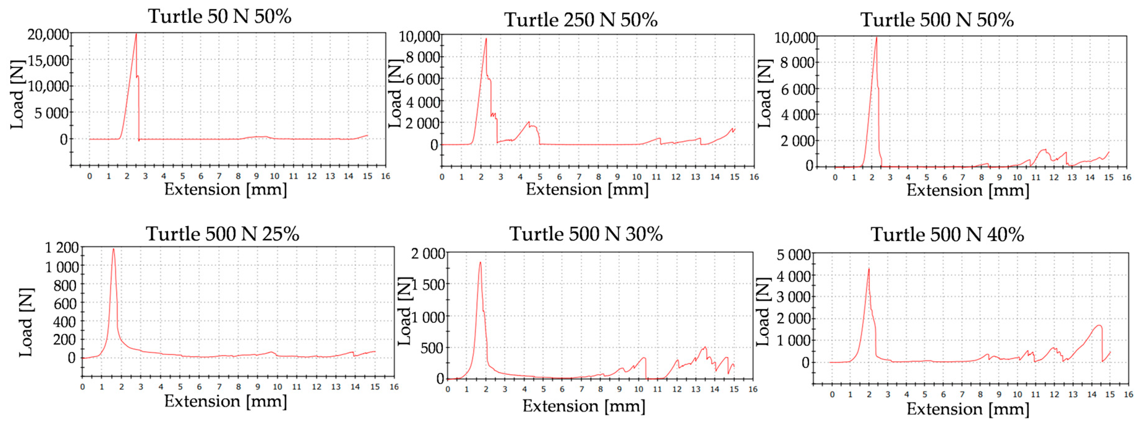
The spiderweb structures (
Figure 8) behaved similarly to the turtle shell structures with some few variations (
Figure 9b). The 50 N, 250 N, and 500 N at 50% all met structural failures at an extension of 2.3 mm to 2.4 mm. None of them exceeded the 25,000 N maximum load parameter and, therefore, all crashed. The 500 N structures at 25%, 30%, and 40% met a maximum load value of 1200 N, 1800 N, and 4200 N, respectively. It was noticed that the extension of the platens, in mm, has an exponential correlation with the amount of load, in N, that is experienced by the structures. For the four different 500 N load values (topology of 25%, 30%, 40%, 50%), the extensions were 1.5 mm, 1.6 mm, 1.9 mm, and 2.2 mm. These extension values corelate with maximum load values of 1200 N, 1800 N, 4200 N, and 10,000 N.
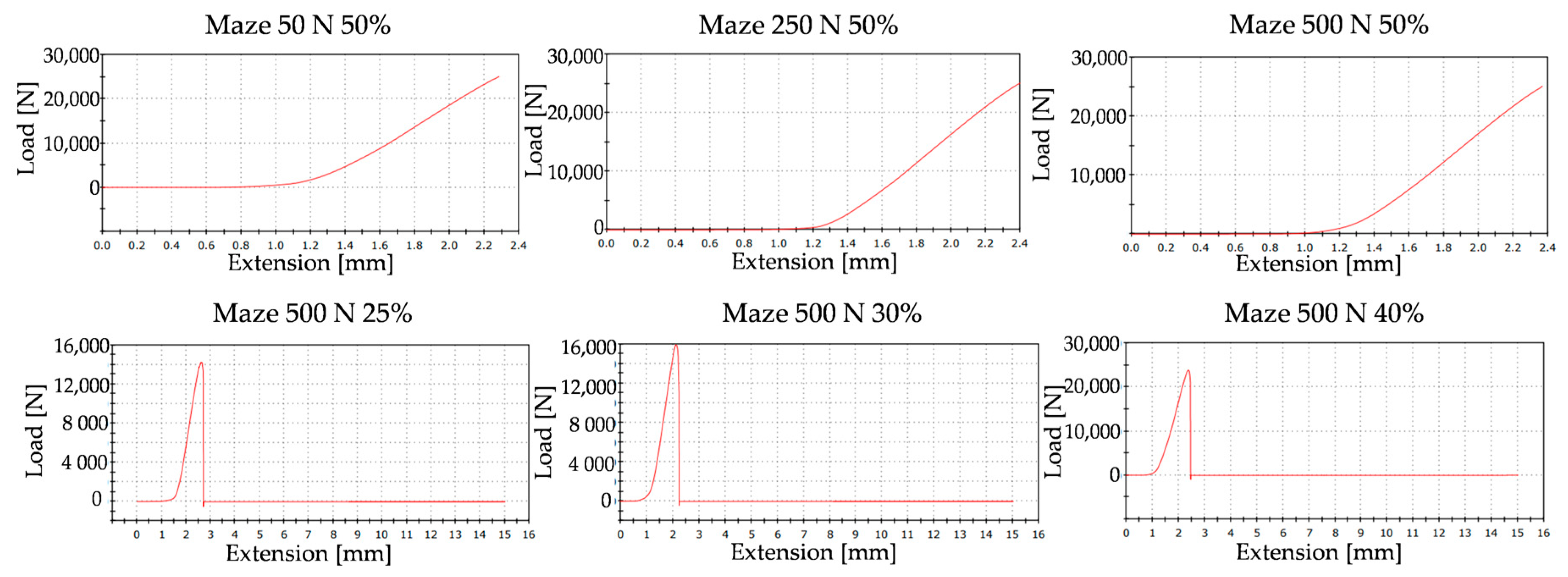
The maze structures (
Figure 9c) behaved a little bit differently than the spiderweb and turtle shell structures in that all three of the 50% (50 N, 250 N, 500 N) exceeded the maximum load parameter of 25,000 N. The 500 N load values of 25%, 30%, and 40% structures had a maximum load value of 14,000 N, 16,000 N, and 23,000 N, respectively. It was also noticed during experimentation that the collapse or failure of the structure at the given maximum loads and extensions was particularly volatile and explosive. This can be seen in the graphs of the 500 N at 25%, 30%, and 40% structures. The graphs are unlike the other two structures in that, at the point of failure, the structure met near complete failure and there was no force detected throughout the rest of the extension of the platen. This can be seen in the results in
Figure 10.
Figure 7,
Figure 8 and
Figure 9 show that compression test results are consistent with the simulation results. All structures are capable to support the design load (<500 N) as all their maximum load (point of failure) exceeded 10,000 N. For the same load and same material reduction ratio, failure load for the spiderweb structure is lower than that of the maze (~16,000 N) and the turtle shell (~18,000 N). The turtle shell structure performed stronger than the other two structures. This validated the simulation results. Comparing the same type of structures (e.g., spiderweb), with the increase of design load, the topology optimized structures will bear a higher load in the compression test. This is also consistent with the simulation results as shown in
Table 3 and
Figure 3.
Comparing with the bare line design, the topology optimized structures bear less load due to the reduction of materials. However, these structures can still hold more load than the designed load. The simulation and testing results show that all optimized structures, based on 75% weight reduction, are able to hold the designed load. These structures can be used in lightweight applications for material saving, cost reduction, and function improvement. It needs to be noted that the case study shown here only has load from one direction. Loads from multiple directions or uneven loads will be studied in future research.
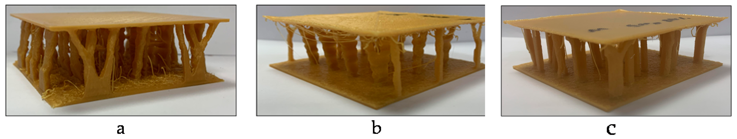
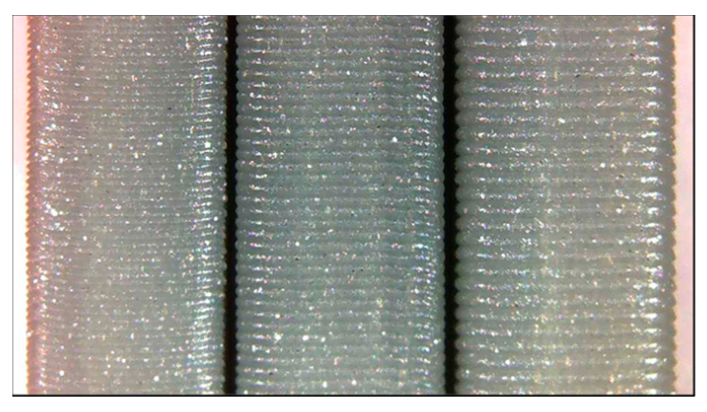
The test of prototypes was also on the surface finish of the parts. They were printed with three different layer sizes, Fine 0.1 mm, Normal 0.15 mm, and Fast 0.2 mm, using the same printing parameters as described above. As the layer height increases, the layers become more visible and increase surface roughness. Some defects were present in the finished prototypes as well. For example, some structures appeared to have been warped. The overall surface finish of these prototypes was also covered with small dents and voids in some places. This caused the structures to have a rough surface finish. These three different layer heights can be seen in
Figure 11 below.
However, using smaller layer heights would have greatly increased the printing times for each structure. Each structure was printed using a layer height of 0.15 mm to minimize layer visibility without significantly increasing printing time. Regardless of layer height, the printing times for the nonoptimized structures were significantly longer than the optimized structures, with the spiderweb taking 36 h to print, the turtle shell taking 31 h, and the maze taking 31 h. The optimized structures (50% mass reduction) took around 10 less hours to print with the spiderweb taking 25 h to produce, the turtle shell taking 25 h, and the maze taking 20 h. This decrease in lead time was because significantly less material was used in the optimized structures. Not only did this reduction in material lead to a decrease in lead time, but it also showed a reduction in the environmental impacts created by each structure. When comparing the emission factors and amount of energy consumed by the optimized and nonoptimized structures, the optimized structures produced less emissions.
Table 4 below display the data associated with the emissions for both the optimized and nonoptimized structures. For emission factors, this study used Virginia electricity emission factors 0.35 kg/kWh CO
2, 0.18 g/kWh SO
2, and 0.32 g/kWh N
2O [
56].
From the tables above, it can be seen that the optimized structures have significantly lower emission factors than the nonoptimized structures. Because the purpose of environmental impact assessment is to examine emission savings across structures, the experiment only used optimized structures based on 50% mass reduction. These tables also show that the spiderweb structure had a significant decrease in energy consumption after optimization. The nonoptimized spiderweb consumed 8.02 kWh, while the optimized version only consumed 6.04 kWh. The turtle shell showed the smallest amount of reductions across all three structures. This could be partly because the turtle shell structure required the least amount of material. The maze showed the greatest reductions, with printing time being reduced by 12.05 h and energy consumption being reduced by 2.67 kWh. Optimizing each structure proved to be an effective way to reduce the emission factors associated with manufacturing. For designers and engineers, structure selection should be based on simultaneous considerations on strength, mass saving, and emissions, which have been assessed in this section.
The case study results show that, for lightweight structures, complex structures take a longer time to print and, thus, require higher energy consumption and a higher amount of materials. These structures do not necessarily have uniform strength due to uneven structure material distributions. However, these material structures can be applied to products where concentrated loads are needed. Comparing to solid material stocks, the identified structures resulted in lower environmental impact because of less material use. The energy consumption of identified structures is not comparable with solid blocks because they require different manufacturing processes. As for the quality, the surface roughness of printed parts is relatively higher than machined parts. Therefore, usually post processes are often needed if the application has a high surface finish requirement. More importantly, the systems thinking based bioinspired material structure design approach is demonstrated and validated through this case study. Material scientists and design engineers can use this case study as an example for various material structure design applications.
Approaches for lightweight structure design have been developed in prior research studies. These approaches include rule-based lightweight structure design [
57], multiple phase design exploration method [
58], and co-optimization design method [
59]. Rule-based design framework includes four steps voxelization, initialization, structure evolution, and evaluation (FEA), and feedback. The difference between this method with the proposed systemic bioinspired design approach is that the start of the design for rule-based design is voxelization that discretizes the input model into the voxel’s domain, while the proposed approach in this study starts with the customer’s requirement design, which does not involve an initial concept that could inhibit the creation of design [
57]. The multi-phase design exploration method starts with a nonparametric optimization on an initial structure and then applies key shape parameters to conduct an inductive design exploration which defines a rough design space and generates discrete points, evaluates the generated discrete points using employed mapping models, and sequentially identifies the feasible regions to satisfy the given performance requirements. The systems thinking based approach, however, conducts topology optimization at a later stage because it identifies bioinspired structures at the first place that targets at meeting functional requirements and then refines the design with topology optimization. This provides more feasible solutions for designers to evaluate at later stages [
58]. The co-optimization design method applies to designs where connection structures are needed. The method uses feature size optimization, obtains the force routine of main part bodies, and constructs the main structure of the design before selecting final structural units [
59]. This is particularly useful when designing material structures that are specifically made for a product application. The proposed systems thinking approach primarily focuses on basic material structure units that are for universal applications. However, integrating co-operative optimization design in the proposed approach will bring unique advantages when designing complex part structures where interconnections are key constraints in a product design.
4. Discussion and Conclusions
This research developed a systems thinking based approach to assist material structure design using bioinspired design and topology optimization. Multiple lightweight structures, such as butterflies’ wings [
32] and honeycombs [
17], were developed by observing nature phenomenon. Existing approaches focus primarily on macro scale product design with specific functionalities [
16,
60]. Very limited studies used bioinspired concepts in material structure design [
32,
61,
62]. Therefore, there is a lack of systemic method to guide material scientists to learn from nature and find the ideas for material structure design. The approach incorporates systems thinking philosophies, such as boundary, understanding, uncertainty, and delays, into a practical method to guide material structure designers to learn from natural materials and use a topology optimization algorithm to modify the structure to fit the material functional environment. A case study was conducted on three structures, including two bioinspired structures (turtle shell and spiderweb) and a maze structure. From the analysis of the three structures, it shows that the high stress and displacement of lightweight structures largely depend on the infill pattern of the material structure. The surface areas with voids inside present higher stress and displacement than the areas with infill supports. Among the three structures, the turtle shell structure had areas with minimum stress and displacement, but also had areas with the highest stress and displacement. Therefore, this material structure can be used to design products that require critical support at certain places but less support in other places. The spiderweb structure, compared with the other two structures, retained some horizontal structures after topology optimization. This unique nature provides the spiderweb structure more support in critical areas than the other two. Therefore, spiderweb material structure can be used in environments similar to the environment for turtle shell but is a more preferred option. The maze structure can be developed based on algorithms. In this case study scenario, the structure shows the pressure on the material was more evenly distributed. Therefore, the maze structure can be used in environments such as surface support that require overall strength of the material. The systems thinking approach also integrates manufacturing consideration and sustainability systemically in the material design, enabling engineers to take a comprehensive view of quality, cost, and environmental impact in the design phase, and avoid unintended consequences that could be caused by lack of manufacturing considerations. This approach can potentially be integrated into computer aided drawing systems for design engineers to use bioinspired design concepts in material structure design and product design. Designers will be able to use the concept guideline to define design requirements and boundaries, select bioinspired concepts, and choosing basic material structure in product design.
The proposed approach can be applied in multiple arenas. First, the approach is developed for material scientists to create new material structures by learning from nature phenomenon. These new material structures can be targeted at applications, including lightweight structures for the automotive industry, composite material structures for the aerospace industry, and innovative nanomaterial structures. Second, the approach is developed for material design engineers to be innovative in creating products that have special requirements, such as strength-to-mass ratio, in the fiber and textile industry.
This research closes a knowledge gap of bioinspired design methods for macro level material structures design for industrial application. Using systems thinking, this study incorporated systems science into bioinspired material structure design for innovation. In addition, by studying the physical properties of some identified structures, materials engineers can use the research result to design lightweight materials for industrial applications, such as vehicles and aerospace products. However, this study is currently limited to three structures. More structures, such as bone, auxetic, and lily pad, can be explored using the proposed systems thinking based bioinspired material design approach. Future research will study the impact of different maze structure design algorithms on material mechanical properties. While this study focused on identifying structure weakness and strength, future studies can also be focused on mechanical behaviors, such as fatigue and fracture, with different materials or comparisons among metal, ceramic, and plastics.


