Review

Generation of 8–20 μm Mid-Infrared Ultrashort Femtosecond Laser Pulses via Difference Frequency Generation

1
School of Science, Beijing Jiaotong University, No. 3 Shangyuancun, Haidian District, Beijing 100044, China
2
Optoelectronics and Measurement Techniques, University of Oulu, 90570 Oulu, Finland
*
Author to whom correspondence should be addressed.
Photonics 2022, 9(6), 372; https://doi.org/10.3390/photonics9060372
Submission received: 4 May 2022 / Revised: 18 May 2022 / Accepted: 20 May 2022 / Published: 25 May 2022

Abstract

:
Mid-infrared (MIR) ultrashort laser pulses have a wide range of applications in the fields of environmental monitoring, laser medicine, food quality control, strong-field physics, attosecond science, and some other aspects. Recent years have seen great developments in MIR laser technologies. Traditional solid-state and fiber lasers focus on the research of the short-wavelength MIR region. However, due to the limitation of the gain medium, they still cannot cover the long-wavelength region from 8 to 20 µm. This paper summarizes the developments of 8–20 μm MIR ultrafast laser generation via difference frequency generation (DFG) and reviews related theoretical models. Finally, the feasibility of MIR power scaling by nonlinear-amplification DFG and methods for measuring the power of DFG-based MIR are analyzed from the author’s perspective.

1. Introduction

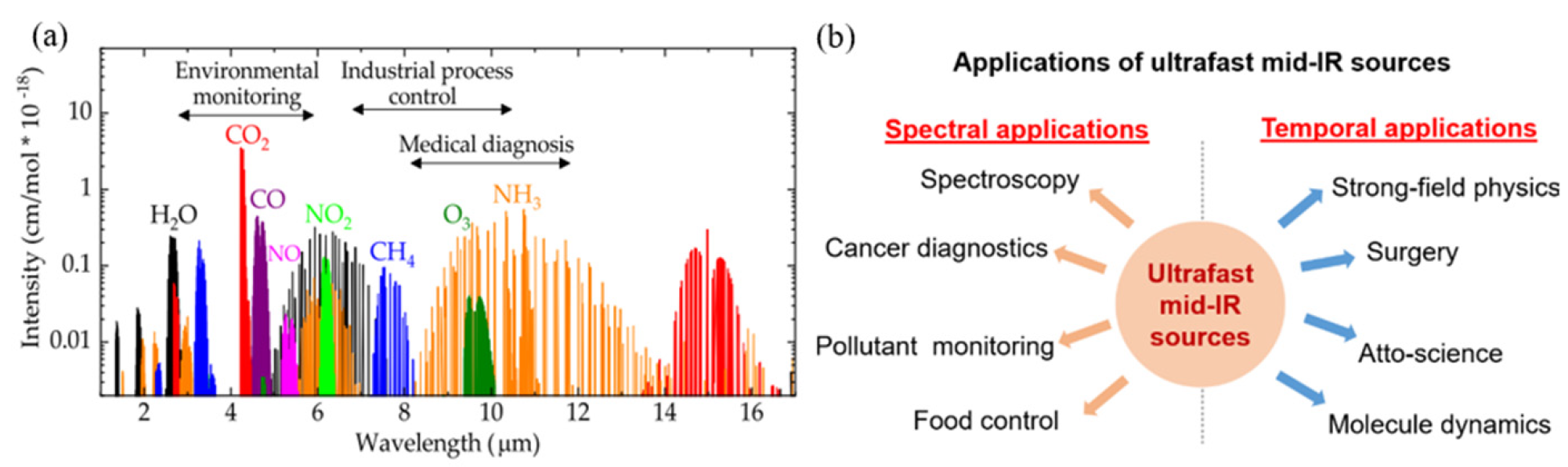
1.1. Motivations for the Research of the Mid-Infrared Region

The mid-infrared (MIR) spectral region is known as the “molecular fingerprint region”, and almost every kind of gas molecule shows a unique and strong absorption characteristic within that region, as shown in Figure 1a [1,2,3,4,5,6,7]. The MIR ultrashort pulsed lasers can be widely used in gas detection [7,8], cancer diagnosis [9,10,11], pollutant monitoring [12,13,14,15,16], food quality control [17,18,19,20,21,22,23], and other aspects [24,25,26,27,28], since they own much broader spectral ranges than ultrafast lasers in visible and near-infrared region. In addition, they also play essential roles in strong-field physics [29,30,31,32,33,34], laser surgery [35,36,37,38,39,40,41], attosecond science [42,43], and molecule dynamics [44,45,46] (as shown in Figure 1b), as they feature the ultrashort time domain and have the potential to achieve peak powers. Therefore, there is an essential and broad application value in MIR ultrashort pulse generation research.

1.2. Methods for Mid-Infrared Generation Technology

MIR application is driven by the development of laser technology in related wavelengths. For example, the emergence of MIR laser frequency combs has facilitated the research process of highly sensitive (up to the order of several parts per billion (ppb)) molecular spectroscopy detection techniques [2]. Therefore, the timely promotion of the research on MIR coherent light sources is crucial to the development of science, technology, national defense, industry, medicine, and other applications. In the last decade, continuous breakthroughs and improvements have been made in the performance of MIR laser technology with regard to power, efficiency, wavelength range, time/frequency domain, beam quality, and stability [1,2,3,4,5]. The designs of the lasers have become increasingly compact, practical, portable, and miniature. However, due to the lack of suitable gain materials, the output of conventional solid-state lasers and fiber lasers cannot cover most of the MIR region, especially the long-wavelength MIR band of 8–20 µm. The application and development of spectroscopy in this band have been limited by the low laser power, narrow tunable wavelength range, and unstable operation [1,2,3,4,5]. At present, the main technologies for long-wavelength MIR laser generation include stimulated radiation methods (e.g., free-electron lasers, lead-salt semiconductor lasers, and quantum cascade lasers (QCLs)), and the nonlinear frequency conversion methods. Free-electron lasers are large, expensive, and usually used for X-ray pulse generation [47,48]. Lead-salt semiconductor lasers have low output power (about 0.1 mW), and require low-temperature cooling to achieve regular state operation, which are exceptionally sensitive to changes in temperature [8]. Due to the limited wavelength-tunable ranges of QCLs, it is usually required to use several QCLs with different working wavelengths, which is inconvenient and has high costs. Furthermore, mode-locking is hard to be realized in QCLs due to their picosecond-level gain recovery time. The picosecond-level laser pulse at 8 µm was only recently, in 2020, achieved in QCLs [49], and femtosecond pulses were generated via spectral filtering, gain modulation-induced spectral broadening, and external pulse compression in 2021 [50].
The nonlinear frequency conversion methods, including optical parametric oscillation (OPO), optical parametric amplification (OPA), difference frequency generation (DFG), and supercontinuum generation (SCG), have become the primary techniques to build up MIR ultrafast lasers above 8 µm. The principles of OPO, OPA, and DFG are shown in Figure 2 [51]. The OPO setup consists of a nonlinear crystal and a resonant cavity, which allows the signal or idler light or both of them to oscillate in the cavity to obtain the desired wavelength. In nonlinear crystals, the pump, signal and idler lights are overlapped, and the interaction between them leads to the corresponding gain obtained by the signal and idler light. The physical processes of DFG and OPA are basically the same and both require two beams of light (pump and signal lights) to interact in the nonlinear crystal. OPA aims to amplify the original signal light or to obtain high-energy idler light, while DFG aims to obtain high-average-power idler light. DFG is suitable for both continuous-wave and pulsed operation, while OPA is only suitable for pulsed operation. In addition, the signal light in the general OPA process is very weak compared to the pump light in power, while the signal light in the DFG process is stronger.
SCG is another effective nonlinear frequency conversion method for MIR generation. A supercontinuum is mainly generated from high-nonlinearity fibers, waveguides, or bulk crystals. In SCG, several nonlinear physical processes usually work together, such as self-phase/cross-phase modulation (SPM/XPM), parametric four-wave mixing, Raman scattering, soliton generation, soliton fission, soliton self-frequency shift, dispersive wave, and so on [5]. The current commercial product has already been available in the 2–5 µm of the MIR region [52]. However, the spanning range of supercontinuum greatly depends on the nonlinear material especially for MIR wavelengths longer than 5 µm or even 8 µm. Silicate glass is one of the most common and typical materials for SCG shorter than 2.5 µm. ZrF4-BaF2-LaF3-AlF3-NaF (ZBLAN) glass can extend the SCG wavelength to 10 µm. Chalcogenide glass, such as sulfur (S), selenium (Se), and tellurium (Te), is considered to be the most potential material for longer wavelength MIR generation [5,52,53].
The main drawback of OPO is the additional complexity brought by the resonant cavity and the relatively limited oscillation spectral range. It usually works in the region of 3–5 µm. Recent efforts show that the OPO-based MIR source could span over 8 µm by employing nonlinear crystals such as orientation-patterned gallium phosphide (OP-GaP) and silver gallium sulfide (AGS), owing to their long-wavelength transparency [54,55,56]. OPA usually works at a low repetition rate (from one to several hundreds of kHz level) but with high pulse energy (from one to several hundreds of μJ level), aiming to pursue high peak power or pulse energy in the MIR region [57,58,59,60,61,62,63,64,65,66,67,68,69,70,71]. However, there is still not much work regarding OPA working under an MHz repetition rate of over 10 μm because of the thermal effects. Many research efforts have shown that wavelengths generated by SCG could span over 8 µm or even 10 µm with the power of tens of milliwatts under well-engineered material structures [72,73,74,75,76,77,78,79,80,81,82,83,84,85,86,87,88,89,90,91,92,93,94]. However, long-wavelength (ranging from 2 to 9 µm) femtosecond pump sources with relatively high power (at least hundreds of milliwatts) and high-nonlinearity material are necessary for long-wavelength MIR generation by SCG, regardless of the pumping scheme (direct pumping or cascaded pumping). This makes the whole process more complicated since all the components mentioned above are not commercially available.
Nowadays, DFG is one of the most important techniques to achieve high average power MIR with a high repetition rate and has become an effective tool to generate optical frequency combs [51]. When the repetition rate is locked, the pump and signal pulse sequences come from the same oscillator and share the same carrier-envelope offset (CEO). This offset is automatically eliminated during the DFG process, resulting in a stable optical frequency comb. DFG has not only been applied to MIR but also to THz generation as the two wavelengths participating in the process are controllable. Thus, there is no doubt that DFG is still the mainstream method for generating MIR pulses. This paper mainly focuses on the recent MIR (8–20 μm) ultrashort pulse generation research by DFG-based technologies and analyzes the current problems existing in the experimental setup. Some theoretical works for the simulation of DFG are also introduced to provide guidance for experimental works. Finally, we will discuss the feasibility of MIR power scaling by nonlinear-amplification DFG from the author’s point of view.

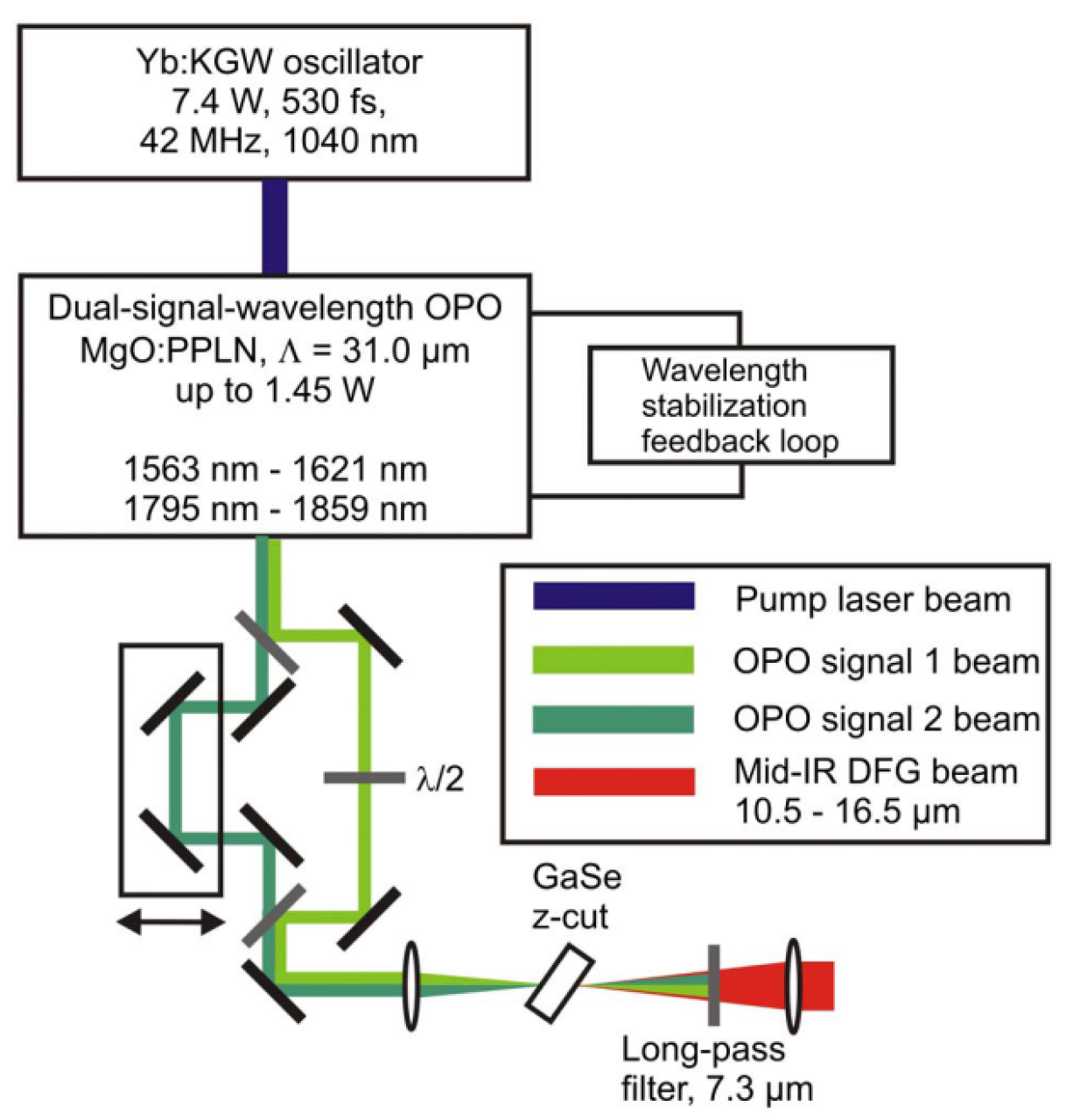
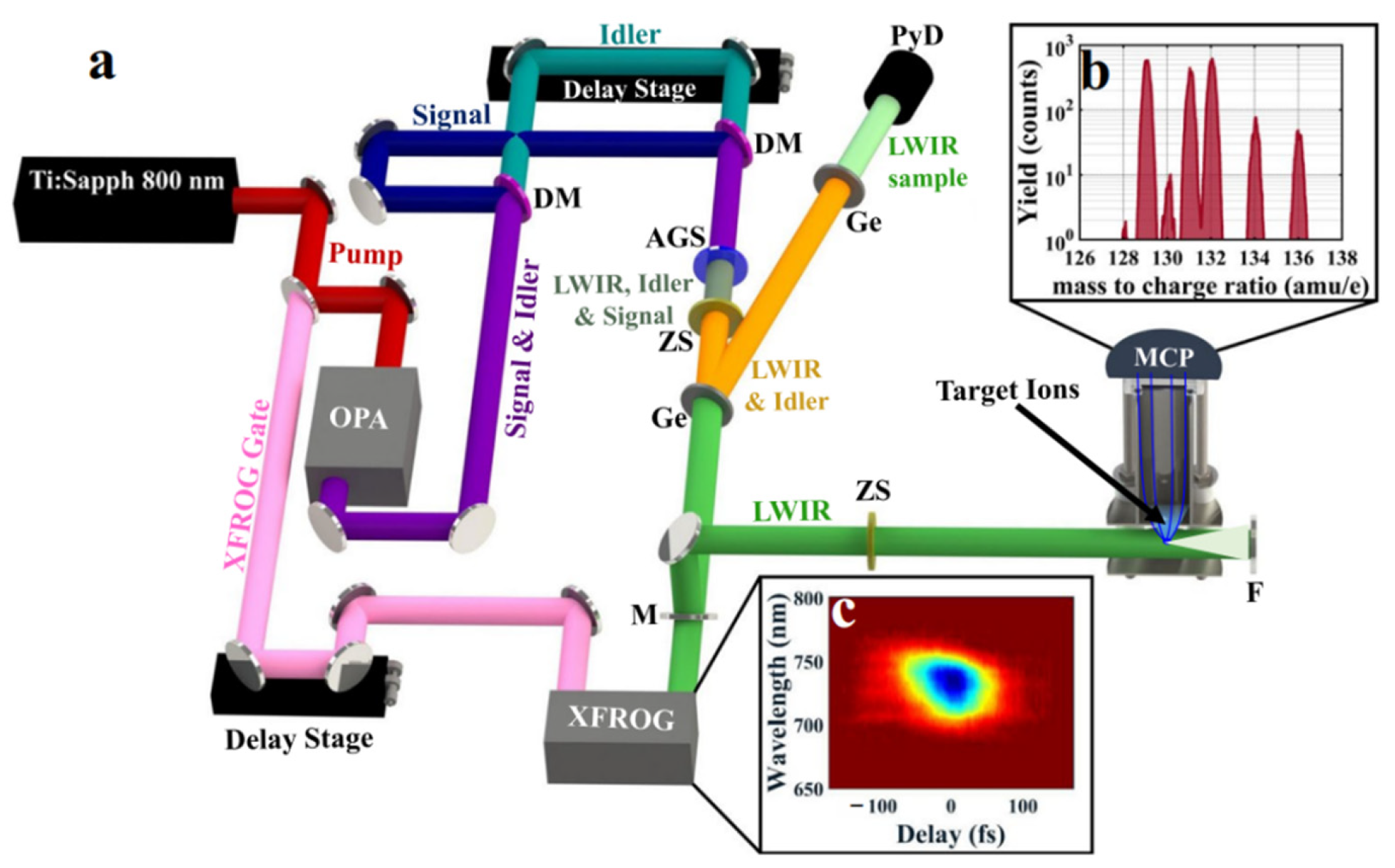
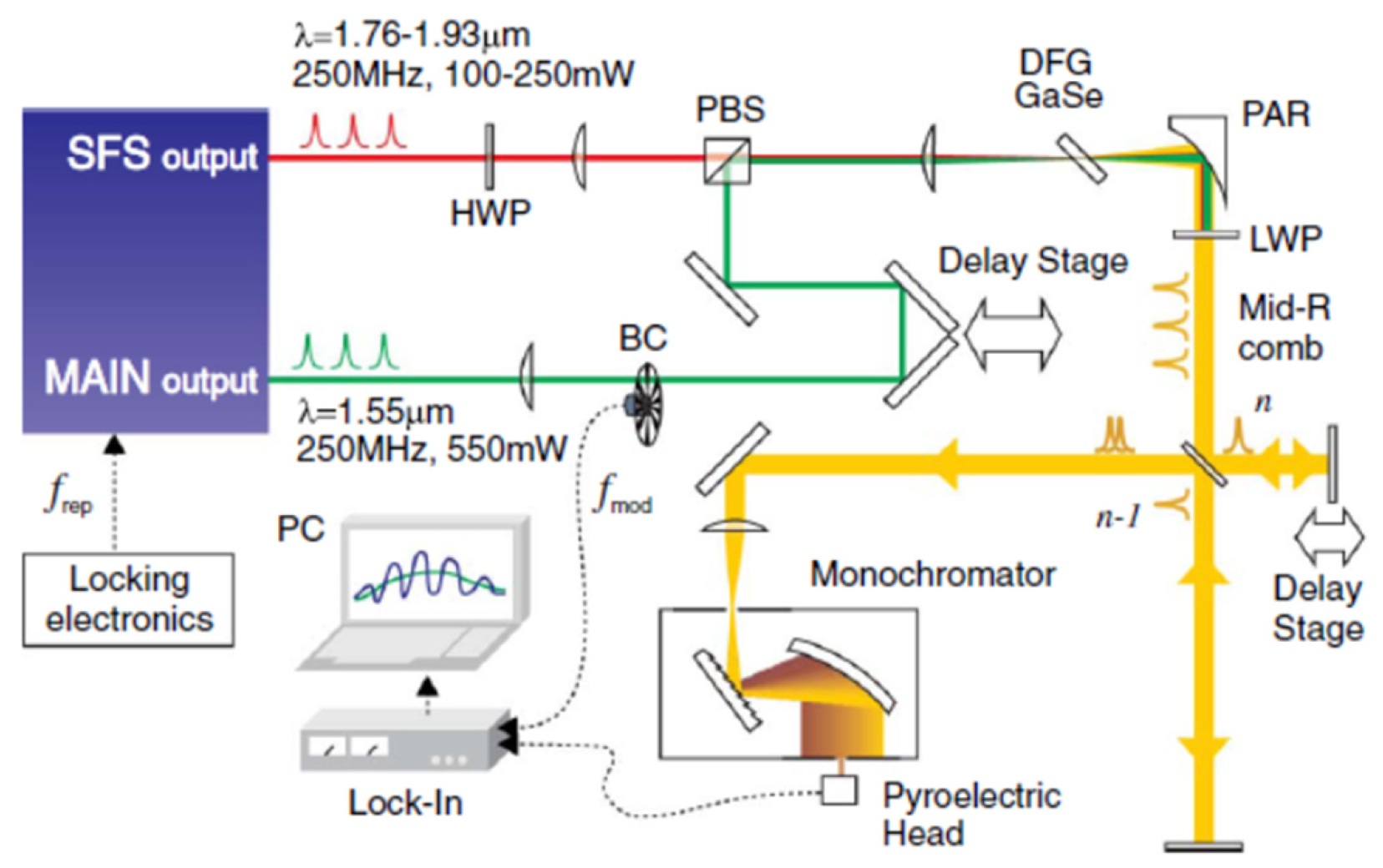
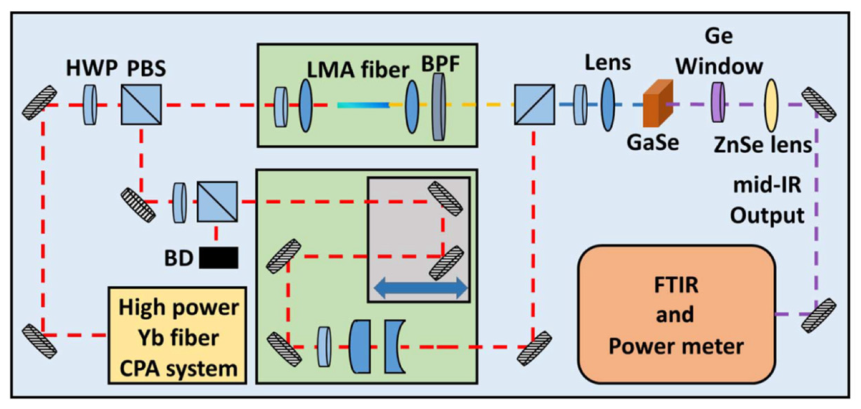
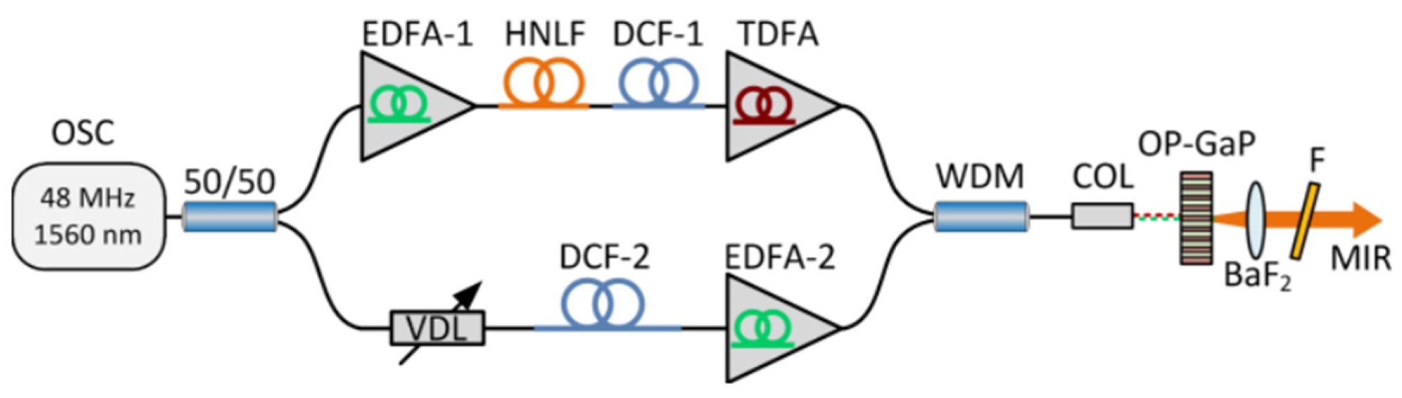
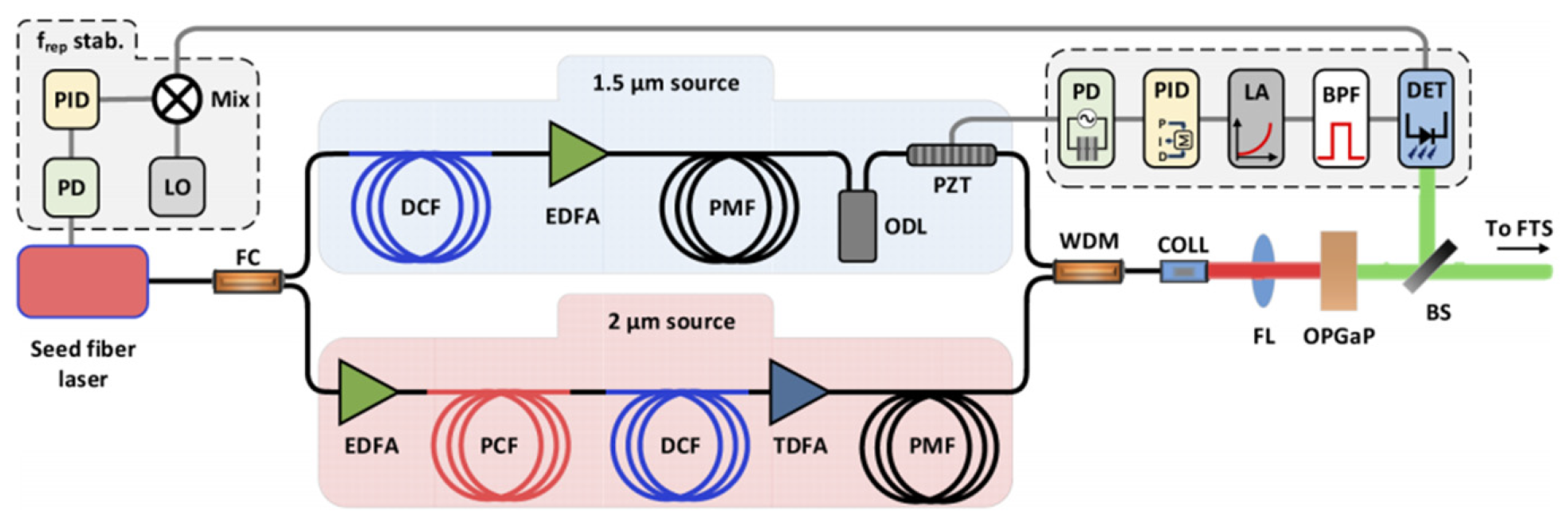
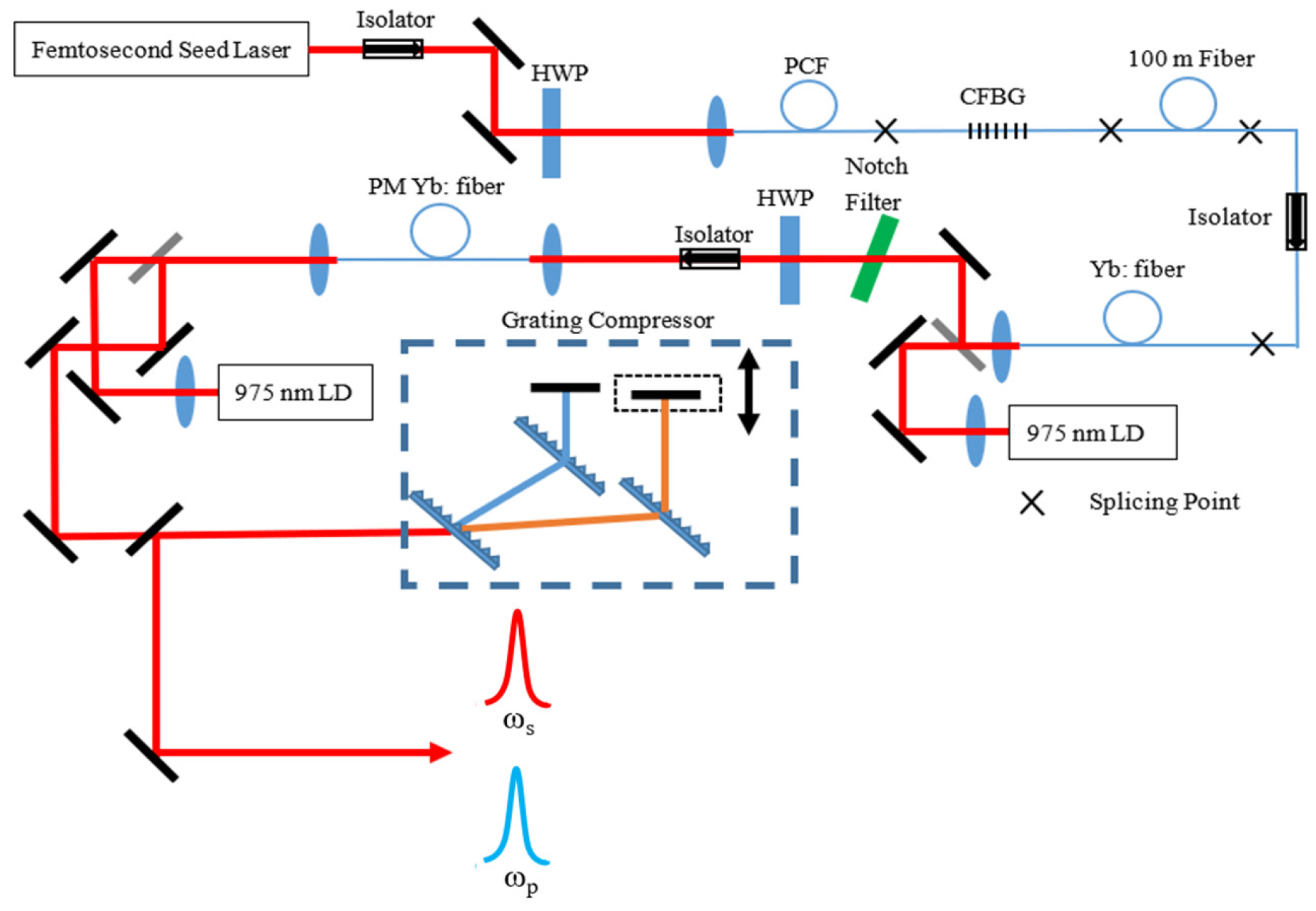
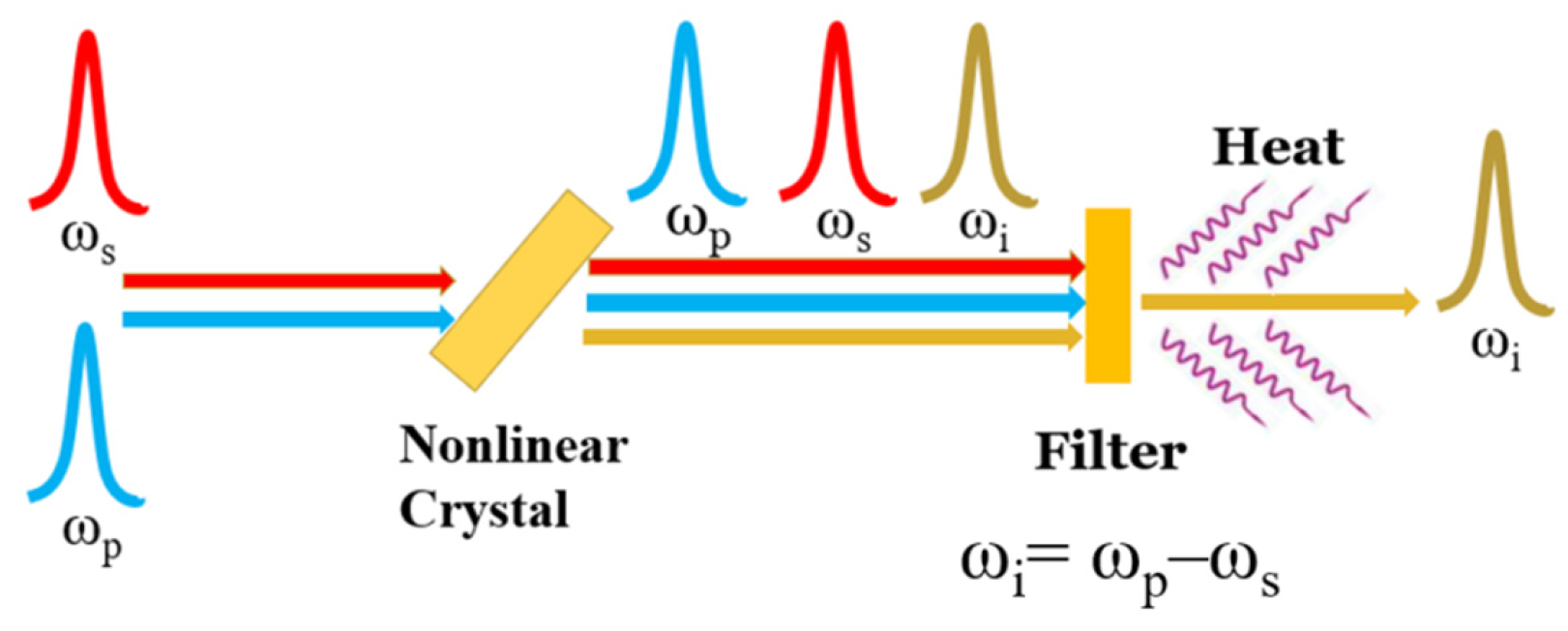
2. Experimental Study of Long-Wavelength Mid-Infrared Laser Sources Based on DFG

Early DFG schemes are mainly based on bulky Ti: Sapphire femtosecond pulsed laser systems to generate dual-wavelength synchronous pulses, restricting the average power of the MIR below the milliwatt level due to the thermal load [95,96,97,98,99,100,101,102]. Modern DFG schemes that can achieve relatively high powers are mainly based on dual-wavelength OPO, OPA, and ultrafast fiber laser systems [103,104,105,106,107,108,109,110,111,112,113,114,115,116,117].
A MIR femtosecond pulsed laser with a wide tuning range (5–17 μm) and an average power of 69 mW at the wavelength of 6 μm was achieved by Beutler et al. based on the DFG in AgGaSe2 crystals utilizing a synchronously pumped OPO ultrafast laser source in 2015 [106]. A DFG-based MIR laser with an average power of 4.3 mW and a 10.5–16.5 μm wavelength-tunable range (as shown in Figure 3) was built by employing a two-color femtosecond OPO system in 2012 by Harald Giessen’s research group of the Fourth Institute of Physics at the University of Stuttgart, Germany [107]. Later in 2016, a highly stable MIR 350-fs pulsed laser system with nJ-level pulse energy and an ultra-wide tunability ranging from 1.33–2.0 μm and 2.13–20 μm has been achieved by Giessen’s group by combining OPO, OPA, and DFG technologies [108]. More recently, Wilson et al. proposed a DFG scheme for MIR generation tunable from 3.5 μm to 9 μm in 2019. They utilized a few-cycle Ti: Sapphire laser to pump an OPA to generate a total power of up to 6 mJ of signal (1300–1450 nm) and idler (1730–2000 nm) lights in the NIR. Then, the two synchronous pulses were used for the DFG process, and a maximum of 120 μJ at 5.3 μm and up to 80 μJ at 8.9 μm center wavelengths with 70–90 fs of pulse width were obtained through their setup (as shown in Figure 4) [109].
Ultrafast fiber lasers have been adopted as the pump sources in some DFG experiments due to their high surface-area-to-volume ratios, strong heat dissipation performances, high repetition rates and average powers, as well as all-fiber compactness. The output pulses from a fiber laser are usually divided into two parts for MIR generation. One part is used as pump pulses and the other produces a new spectral component on the longer wavelength side through the nonlinear fiber effect as wavelength-tunable signal pulses [110,111,112,113,114,115,116,117].
In 2013, Gambetta et al. reported a MIR pulsed laser with a tunability of 8–14 μm and a maximum average power of 4 mW in GaSe crystals (as shown in Figure 5) [111]. In the experiment, the Er: fiber laser oscillator (1.55 μm, 50 fs, and 550 mW) was used as the pump pulse, while the self-frequency shifted (SFS) soliton pulse (1.76–1.93 μm) generated from the nonlinear Raman fiber was serving as the signal pulse. The synchronism of the two pulses was adjusted through the optical delay line, and the tunable output of the MIR laser pulses was generated in a 1 mm-thick GaSe crystal. Zhou et al. developed an Yb: fiber laser system with an average power of 14.5 W, a repetition frequency of 30 MHz, and a pulse width of 165 fs. The output pulses of the system are divided into two parts in the optical path through the half-wave plate (HWP) and the polarization beam splitter (PBS). A portion of the pulses acted directly as pump pulses of the DFG. The other part of the pulses passed through a large-mode field fiber (4 cm), then the 125 fs signal pulses with the wavelength-tunable range of 1030–1215 nm were generated through the self-phase modulation effect. In the GaSe crystal, MIR pulses with a highest average power of 5.4 mW and a tunability between 7.4 and 18 μm (as shown in Figure 6) were finally obtained [114].
In 2019, Ma et al. proposed an all-polarization-maintaining fiber amplification method (except the optical delay line) for MIR generation [117]. The dual-wavelength pulses are split by an optical fiber coupler and enter different nonlinear amplification systems. Finally, the peak wavelengths of the two pulses are separated at least by 50 nm. The MIR generation from the system can be tuned from 7 to 10.5 µm. In 2018, Sotor et al. reported a MIR source ranging from 6 to 9 µm based on an all-fiber system [115]. The pulses from the oscillator were split and travelled through different fiber amplification models. However, a fiber-coupled delay line was used to control the synchronism of the pulses, making the front-end system truly all-fiberized (as shown in Figure 7). The maximum output power of the DFG was 7.4 mW with a repetition rate of 48 MHz at 7.5 µm, and the power was kept at 1 mW over the entire tuning range. More recently, Sotor et al. updated their system by adding a repetition rate stabilization model and a pulse-synchronism controlling model [116], which realized the stabilization of the repetition rate and the temporal pulse overlap in the MIR generation. An average power of 5 mW was obtained in the tunable range of 6.5–9 µm at 125 MHz (as shown in Figure 8).
In recent years, the intrapulse difference frequency generation method (IDFG, also known as optical rectification) has become a new method to generate MIR laser source owning to its simplicity and phase stability [118,119,120,121,122,123,124,125,126,127,128,129,130,131,132,133,134,135]. The coherent femtosecond-level pulses with a wavelength range covering the whole MIR region are successively realized through IDFG. Only one beam of femtosecond pulses is needed to travel through the nonlinear crystal to obtain MIR pulses, making it structurally simpler than general DFG. However, IDFG involves a variety of nonlinear effects, and the mechanism is relatively unclear. The demand for relevant pump pulse width (usually few-cycle pulses) is also challenging to meet. Furthermore, tunability seems hard to realize since a very broad spectrum is generated via IDFG. In addition, for output wavelength longer than 10 μm, especially over 15 μm, the optical-optical conversion efficiency (MIR power/pump power) drops by tens of times compared to the short wavelength (see Table 1) regardless of the traditional DFG technology or the emerging IDFG technology.
Donna Strickland’s ultrafast laser group has been working on long-wavelength MIR pulse generation for tens of years, aiming on output wavelengths of over 16 μm based on the dual-wavelength ultrashort pulsed laser system and the DFG method [136,137,138,139,140]. In 2012, an 18 μm pulsed laser with an average power of 30 μW under subpicosecond level was achieved with the Yb: fiber amplification system, and the wavelength is tunable between 16 and 20 μm [138]. However, the experimental system is composed of bulk-optic elements, which is large, inefficient, and unstable. In 2018, they switched the whole bulk-optic system into a partially fiberized structure by replacing the traditional spatial grating with the chirped fiber Bragg grating as the wavelength selector, and two target wavelengths (1025 nm and 1085 nm) are selected. The dual-wavelength seed source was then amplified in the subsequent two-stage amplification system. As a result, the compact two-color femtosecond chirped pulse amplification (CPA) system with high average power (as shown in Figure 9) was achieved [139]. Furthermore, based on this system, a 17.4 μm MIR pulsed laser output with an average power of 2.5 mW was achieved by DFG under the condition of tight-focusing [140]. Compared to the previous work in 2012, not only was the MIR power increased by about 80 times, but the stability was also improved [138].
In conclusion, the efficiency and stability of the current DFG laser systems can be vigorously improved if the following drawbacks can be addressed:
First of all, the components of the most current systems are partially fiberized, and structures of bulk-optic components are still adopted in the amplification and pulse compression modules, resulting in low conversion efficiency, significant loss, and strong instability.
Secondly, the increase of the total power of the amplification system is limited by the drawbacks in the process of seed spectrum selection and amplification. The effective spectral component that can be amplified in the seed spectrum selection process only accounts for less than one-tenth of the total power, and the other part of the energy in the supercontinuum is sacrificed. In addition, there are serious gain competitions in the amplification process when the dual-wavelength seeds are amplified simultaneously.
Thirdly, the impact of the accumulation of nonlinear phase shift on the final output pulse width is not considered in the whole CPA system. Compared with the initial seed pulse, the compressed pulse is wider and owns a prominent pedestal. The pulse quality still has a large room for improvement.
Last but not least, the generated MIR wavelength range can only cover 16–20 μm, which is a limited wavelength-tunable range. In addition, the power is also limited in several milliwatts. These two factors severely restrict the application field of the MIR laser source.

3. Theoretical Study of the DFG for Mid-Infrared Generation

In terms of theoretical research, there are few relevant theoretical calculations on transient DFG processes, and the transient model is usually complex. Therefore, the average power of the idler frequency light is always estimated with the steady-state DFG formula. However, since the formula is established under steady-state conditions, it is defective in the states of ultrashort pulses. To this end, the steady-state DFG formula should be modified. At present, the representative DFG formula of correction calculation of MIR power is as follows [141]:
P i = T p T s T i 8 π 2 d e f f 2 ε 0 c n i n p n s λ i 2 A t f P p P s L 2 g .
In Equation (1), Tp, Ts, and Ti are Fresnel transmission coefficients of pump, signal, and idler pulse in nonlinear crystals, respectively. deff is the effective second-order nonlinear coefficient. Pp and Ps are the average powers of the pump and signal light. L is the interaction length of the pump, signal, and idler light in the nonlinear optical crystal. ε0 is the dielectric constant in the vacuum. c is the speed of light in the vacuum. ni, np, and ns are the refractive index of nonlinear optical crystals towards the idler, pump, and signal light at the phase-matching angle, respectively. λi is the wavelength of the idler pulse in a vacuum, f is the pulse repetition rate. t is the average value of the pump, signal, and idler pulse when the pulse widths of the three are assumed to be equal. g is the correction coefficient after considering the walk-off effect. The formula is modified compared to the DFG calculation formula in the continuous-wave state by taking the influence of peak powers into consideration. However, it is still a rough model because the value of the correction coefficient g (0 < g < 1) is not well defined. Moreover, the formula does not consider the thermal effect of the crystal, and there is a significant deviation between the calculation results and the actual experiments [138,141]. Therefore, the computational modified model of the average power of DFG should be reconstructed from the transient equation of the DFG process combined with an amount of experimental data.
Moreover, it is mentioned above that the physical process of OPA and DFG is basically equivalent, hence the generation of idler frequency light also happens in the realization of OPA. This raises new questions: can a critical condition be found during the DFG process by changing the laser power injected into nonlinear crystals to shift the DFG into the OPA process? If so, will the power of the idler frequency behave like an exponential nonlinear growth trend? Efforts have been made to explain the relevant problems through theoretical calculation. For the repetition rate of 30 MHz and the pulse width of 200 fs, the evolution curve of the idler pulse energy was obtained by varying with the pump and signal pulse energy, predicting that there are linear growth, nonlinear amplification, and saturation zones in the DFG process (as shown in Figure 10) [142]. It can be seen that when the signal light power is kept to a certain value, the pump power plays a decisive role in the improvement of the MIR (idler light) power, and the increase of the signal power can easily make the MIR power reach saturation. Therefore, when certain critical conditions of nonlinear amplification are met and the DFG process is transformed into an OPA process, the MIR power will be nonlinearly increased, and the optical-optical conversion efficiency will be greatly improved (>1%).

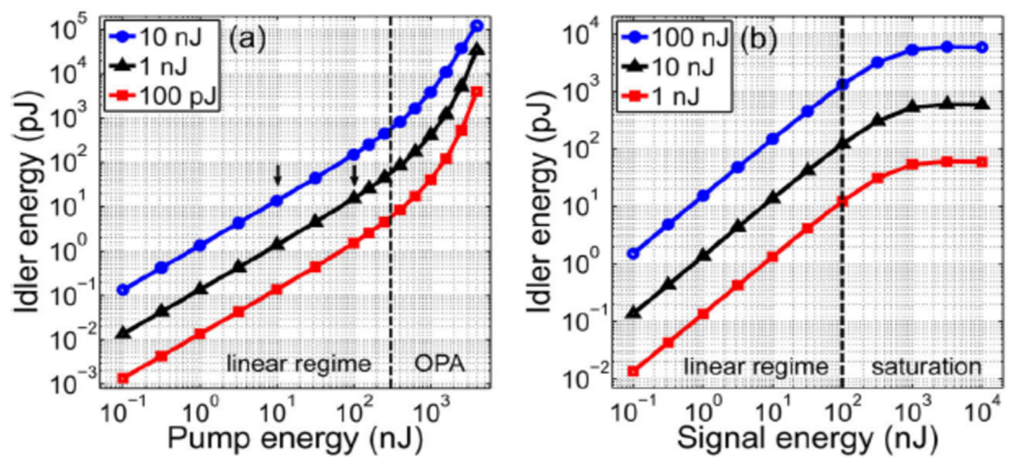
4. Feasibility of Mid-Infrared Power Scaling by Nonlinear-Amplification DFG

Here we present the current problems for MIR ultrashort pulse generation above 8 μm. They are as follows:
(1) For current MIR lasers based on DFG or IDFG schemes, when the output wavelength is longer than 10 μm or even longer than 15 μm, the power will drop rapidly to the order of several milliwatts, and the optical-optical conversion efficiency is relatively low.
(2) Most of the research groups separate the relationship between DFG and OPA, and do not consider the nonlinear amplification and saturation states that appear in the DFG process in theoretical and experimental research.
From the author’s point of view, there is no doubt that IDFG could generate broadband MIR sources with relatively higher power. However, the problem is that the output MIR spectrum is not easily controllable and tunable. Except for picking up crystals with high nonlinearity and transmission, there is much work to be done in the front-end pumping system due to the complexity of overcoming dispersion and nonlinearity problems for obtaining the few-cycle pulses. Compared to IDFG, DFG is still a cost-effective scheme since fiber lasers under hundreds of femtosecond level as pump sources are commercially available and relatively economic. To solve the problem of low power of MIR for the DFG scheme, the following solutions with nonlinear-amplification DFG are proposed:
(1) Make reasonable adjustments to the focused beam size on the crystals. The focused spot size greatly affects the phase matching of the DFG process. In order to achieve high power MIR pulsed laser under DFG scheme, an appropriate laser focusing lens should be selected to optimize the spot size focused on the nonlinear crystal. A small focused spot size will lead to a higher MIR power, but the divergence angle will be too large for the MIR beam to be collected and serious thermal effects and damaging problems will occur. On the other hand, the divergence angle will become small, and the MIR beam will be easy to collect when the focused spot size is large, but the intensity threshold of DFG in the nonlinear amplification region will not be reached. Therefore, the focused spot size should be optimized to make the focused light intensity higher than the threshold for nonlinear amplification and less than the crystal damage threshold to achieve high power MIR pulses.
(2) Adjust the power/pulse energy ratio entering the crystal. As predicted in [142], there are linear growth, nonlinear amplification and saturation regions in the DFG process. The MIR power is proportional to the product of the pump and signal light powers within a certain range. However, a large number of experiments show that it is not feasible to increase the signal power to the same level as the pump power since the wavelengths of the signal are usually not located in the gain curve of the materials. We propose that it is better to deliberately create a power gap between the pump and signal lights, which leads to the transformation of the linear growth state to the nonlinear amplification state and results in a conversion efficiency of >1%. Assuming a pump laser source with 10 W average power and a signal light with 100 mW average power, if the nonlinear amplification state is reached and kept, an average power of no less than 100 mW can be maintained throughout the whole MIR range.

5. Methods for Measuring the Power of DFG-Based Mid-Infrared

As shown in Figure 11, a large amount of thermal radiation is released from the back direction of the long-pass filter due to the strong absorption of the pump and signal lights by the filter. Therefore, when the MIR power is measured by a thermal power meter behind the filter, the thermal radiation released from the filter will interfere with the measurement results, making the measured results much larger than the actual power. Under the condition of our experiment, only one-third to one-fifth of the total measured power shown on the display of the power meter is the real power of the coherent mid-infrared source generated by DFG.
In view of this, we have explored three measurement methods for measuring the power of DFG-based MIR, and their pros and cons are also weighed. Before all the measurement work, we tweak and adjust all components to achieve the highest MIR power.
Method 1: Nonlinear Crystal Rotating Method. Firstly, the total power of the MIR and the heat radiation by the filter is measured behind the filter. Then, the residual power (i.e., heat radiation) is measured when the output MIR disappears completely due to phase mismatch by slightly rotating the crystal by about 3°. Consequently, the power difference between the two measurements can be considered the actual MIR power. This method could achieve multiple measurements in a short time, since it is easy to restore the crystal to the position of the optimal phase-matching angle. The tweaked angle should not be more than 3° because the refraction of the crystal may affect the optical path.
Method 2: Pulse Synchronization Control method. As shown in Figure 9, the synchronism of the two pulses can be adjusted by the optical delay line placed behind the grating pulse compressors. When the two pulses are synchronized, the MIR power is the highest. We first measure the power in this state. On the contrary, if the optical delay line is adjusted so that one pulse is far away from the other, the MIR will disappear. Then the MIR power could be determined by measuring the power difference between the two states. However, because the adjustment of the delay line is too fine, it is difficult to tweak back to the initial optimized position after one-time measurement, which means it will be hard to measure the power several times in a short time.
Method 3: Seed Laser Blocking Method. We first measure the power after the filter as we did in method 1, and then use an opaque plate to block the output of the femtosecond seed laser. When the seed laser is blocked, only ASE exists in the dual-wavelength CPA system. In this state, MIR will not be generated any more. Therefore, the MIR power can be determined by measuring the difference between the two states. Multiple measurements could also be achieved in a short time. However, because the total power of the ASE is not equal to that of the total amplified output power (the power of the ASE is usually lower than that of the power in the normal amplification state), the measurement results are relatively larger than the actual one.
The measurement results by the three methods are shown in Table 2 during our experiment [140], which is the average value obtained by five-times repeating the measurement for each method. It can be seen from the table that the power value and standard deviation measured by method 3 are large due to the thermal effect of the filter, while the results measured by methods 1 and 2 are relatively close. Compared to method 1, a relatively lower result and larger deviation are obtained by method 2 due to the difficulty of tweaking the delay line back. Consequently, method 1 is strongly recommended in the power measurement of DFG-based MIR due to its advantage of simplicity and time-saving.

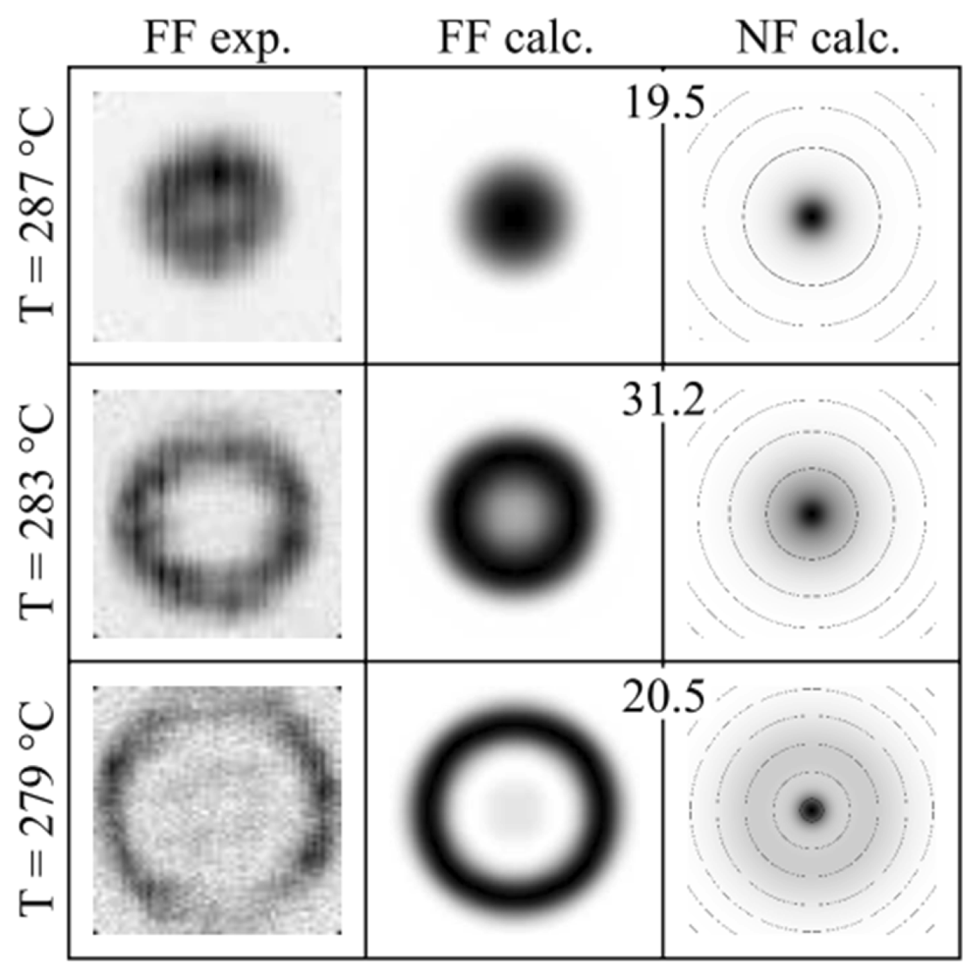
6. Methods for Obtaining a High Beam Quality of DFG-Based Mid-Infrared

The beam quality of DFG-based MIR is also important since there are some application fields requiring high quality MIR beams. The phase-matching condition largely affects the beam quality of DFG-based MIR, and the focused beam radius on the crystal and the crystal temperature are the main factors determining the phase-matching condition. Thus, there are mainly two ways to obtain a high beam quality of the MIR when applying the DFG method: controlling the focused beam size on the crystal or the crystal temperature.
With the tightly focused Gaussian beams, the optimum phase matching does not occur when Δ k = 0 ( Δ k is the phase-mismatch vector) as in the plane wave approximation. As the focal spot size decreases to the dimensions of the MIR generated wavelengths, the axial phase matching is not optimized and the beam begins to propagate as conical emission, which will lower the beam quality. Consequently, a large-size focused beam with a radius of more than 100 μm on the crystal can ensure a better MIR beam quality [140,143].
The crystal temperature is another parameter to determine the MIR beam quality, and there have been some mode-control DFG experiments in the quasi-phase-matched periodically poled lithium niobate (PPLN) nonlinear crystals with different temperatures [144,145], as shown in Figure 12. Because the refractive index is highly related to the temperature in the PPLN crystal, the MIR beam profile is presented with different shapes in thermal imaging as the phase-mismatch vector varies with the temperature. Thus, it can be seen that temperature plays an important role in the MIR beam shaping under the condition of periodically poled crystals. However, there is almost no temperature-dependent research in the long-wavelength MIR region with other kinds of nonlinear crystals.
Considering the currently reported works of the DFG-based MIR beam in the long-wavelength MIR region, thermal radiation is not a very big problem if the focused beam is large enough as most of the research group did not use a temperature-stabilized crystal oven. However, the thermal conductivity of the crystal is still an important parameter if the input peak intensity on the crystal reaches a relatively high value. According to reference [103], the thermal conductivity of LiGaS2 is 3 to 5 times higher than that of AgGaS2 and AgGaSe2 and ~2.5 times higher than the thermal conductivity of layered GaSe along its optic axis, and the thermal conductivity of LiGaS2 is 10.05 W/(m·k) [146]. However, the thermal conductivity of OP-GaP crystal is 110 W/(m·k) according to reference [116,135], which is the highest value to the best of our knowledge. Thus, there is no doubt that OP-GaP is the preferable crystal for DFG-based MIR generation experiment if we only take its thermal conductivity into consideration.

7. Conclusions

To sum up, although great breakthroughs have been made in the research of MIR ultrashort pulse generation, there are still scientific and technical problems to be solved. On the one hand, the quantitative analysis of factors affecting the output optical power in the DFG process is still insufficient, and the critical conditions for the transition from DFG to OPA are unclear. On the other hand, when the wavelength is longer than 15 μm, the currently realized average power of MIR laser pulse is only in the order of milliwatt level, which becomes a bottleneck problem restricting MIR sources from practical application. In addition, the precise measurement for the MIR average power is still challenging. In the present review, discussions on the feasibility of further power scaling in the MIR region above 8 μm, methods for precise measurement of MIR power and obtaining a high beam quality of MIR are provided from the author’s perspective. We believe that the average power of MIR could be increased to the hundreds of milliwatt level at any wavelengths longer than 8 μm through a new nonlinear-amplification DFG method.

Author Contributions

Conceptualization, X.S.; methodology, X.S.; investigation, X.S.; writing—original draft preparation, X.S.; writing—review and editing, X.S., R.Z., B.W., Y.B., T.D., T.S., X.L., J.P. and Y.Z. All authors have read and agreed to the published version of the manuscript.

Funding

This research was funded by the Fundamental Research Funds for the Central Universities (2021RC206), Natural Science Foundation of Beijing Municipality (4182054, 4212052), and the National Natural Science Foundation of China (NSFC) (61527822, 61735005, 61925010).

Institutional Review Board Statement

Not applicable.

Informed Consent Statement

Not applicable.

Data Availability Statement

Not applicable.

Conflicts of Interest

The authors declare no conflict of interest.

References

  1. Ebrahim-Zadeh, M.; Sorokina, I.T. Mid-Infrared Coherent Sources and Applications: Preface; Springer Science & Business Media: Berlin/Heidelberg, Germany, 2008; ISBN 9781402064395. [Google Scholar]
  2. Schliesser, A.; Picqué, N.; Hänsch, T.W. Mid-infrared frequency combs. Nat. Photonics 2012, 6, 440–449. [Google Scholar] [CrossRef] [Green Version]
  3. Pires, H.; Baudisch, M.; Sanchez, D.; Hemmer, M.; Biegert, J. Ultrashort pulse generation in the mid-IR. Prog. Quantum Electron. 2015, 43, 1–30. [Google Scholar] [CrossRef] [Green Version]
  4. Petrov, V. Frequency down-conversion of solid-state laser sources to the mid-infrared spectral range using non-oxide nonlinear crystals. Prog. Quantum Electron. 2015, 42, 1–106. [Google Scholar] [CrossRef]
  5. Vodopyanov, K.L. Laser-Based Mid-Infrared Sources and Applications; John Wiley & Sons: Hoboken, NJ, USA, 2020. [Google Scholar]
  6. Haas, J.; Mizaikoff, B. Advances in Mid-Infrared Spectroscopy for Chemical Analysis. Annu. Rev. Anal. Chem. 2016, 9, 45–68. [Google Scholar] [CrossRef] [PubMed]
  7. Popa, D.; Udrea, F. Towards integrated mid-infrared gas sensors. Sensors 2019, 19, 2076. [Google Scholar] [CrossRef] [PubMed] [Green Version]
  8. Du, Z.; Zhang, S.; Li, J.; Gao, N.; Tong, K. Mid-infrared tunable laser-based broadband fingerprint absorption spectroscopy for trace gas sensing: A review. Appl. Sci. 2019, 9, 338. [Google Scholar] [CrossRef] [Green Version]
  9. Seddon, A.B. Mid-infrared (IR)—A hot topic: The potential for using mid-IR light for non-invasive early detection of skin cancer in vivo. Phys. Status Solidi Basic Res. 2013, 250, 1020–1027. [Google Scholar] [CrossRef]
  10. Tseng, Y.-P.; Bouzy, P.; Pedersen, C.; Stone, N.; Tidemand-Lichtenberg, P. Upconversion raster scanning microscope for long-wavelength infrared imaging of breast cancer microcalcifications. Biomed. Opt. Express 2018, 9, 4979–4987. [Google Scholar] [CrossRef] [Green Version]
  11. Ma, P.; Li, J.; Chen, Y.; Zhou Montano, B.A.; Luo, H.; Zhang, D.; Zheng, H.; Liu, Y.; Lin, H.; Zhu, W.; et al. Non-invasive exhaled breath diagnostic and monitoring technologies. Microw. Opt. Technol. Lett. 2021, 1–14. [Google Scholar] [CrossRef]
  12. Pejcic, B.; Myers, M.; Ross, A. Mid-infrared sensing of organic pollutants in aqueous environments. Sensors 2009, 9, 6232–6253. [Google Scholar] [CrossRef] [Green Version]
  13. Siciliani de Cumis, M.; Viciani, S.; Borri, S.; Patimisco, P.; Sampaolo, A.; Scamarcio, G.; De Natale, P.; D’Amato, F.; Spagnolo, V. Widely-tunable mid-infrared fiber-coupled quartz-enhanced photoacoustic sensor for environmental monitoring. Opt. Express 2014, 22, 28222–28231. [Google Scholar] [CrossRef] [PubMed] [Green Version]
  14. Baudet, E.; Gutierrez-Arroyo, A.; Němec, P.; Bodiou, L.; Lemaitre, J.; De Sagazan, O.; Lhermitte, H.; Rinnert, E.; Michel, K.; Bureau, B.; et al. Selenide sputtered films development for MIR environmental sensor. Opt. Mater. Express 2016, 6, 2616–2627. [Google Scholar] [CrossRef]
  15. Dong, X.; Jochmann, M.A.; Elsner, M.; Meyer, A.H.; Bäcker, L.E.; Rahmatullah, M.; Schunk, D.; Lens, G.; Meckenstock, R.U. Monitoring Microbial Mineralization Using Reverse Stable Isotope Labeling Analysis by Mid-Infrared Laser Spectroscopy. Environ. Sci. Technol. 2017, 51, 11876–11883. [Google Scholar] [CrossRef] [PubMed]
  16. Schulte, S.M.; Köster, D.; Jochmann, M.A.; Meckenstock, R.U. Applying reverse stable isotope labeling analysis by mid-infrared laser spectroscopy to monitor BDOC in recycled wastewater. Sci. Total Environ. 2019, 665, 1064–1072. [Google Scholar] [CrossRef] [PubMed]
  17. Wang, T.; Rodriguez-Saona, L.E. Rapid Determination of Sugar Level in Snack Products Using Infrared Spectroscopy. J. Food Sci. 2012, 77, C874–C879. [Google Scholar] [CrossRef] [PubMed]
  18. Maurice-Van Eijndhoven, M.H.T.; Soyeurt, H.; Dehareng, F.; Calus, M.P.L. Validation of fatty acid predictions in milk using mid-infrared spectrometry across cattle breeds. Animal 2013, 7, 348–354. [Google Scholar] [CrossRef] [Green Version]
  19. Li, X.; Huo, G.; Wang, Y.; Sun, H.; Kong, Q. Research on rapid detection method of protein and fat in raw milk based on mid-infrared spectrum. Int. J. Multimed. Ubiquitous Eng. 2016, 11, 131–142. [Google Scholar] [CrossRef]
  20. Ferreira, D.S.; Galão, O.F.; Pallone, J.A.L.; Poppi, R.J. Comparison and application of near-infrared (NIR) and mid-infrared (MIR) spectroscopy for determination of quality parameters in soybean samples. Food Control 2014, 35, 227–232. [Google Scholar] [CrossRef]
  21. Cocchi, M.; Foca, G.; Lucisano, M.; Marchetti, A.; Pagani, M.A.; Tassi, L.; Ulrici, A. Classification of Cereal Flours by Chemometric Analysis of MIR Spectra. J. Agric. Food Chem. 2004, 52, 1062–1067. [Google Scholar] [CrossRef]
  22. López-Lorente, Á.I.; Mizaikoff, B. Mid-infrared spectroscopy for protein analysis: Potential and challenges. Anal. Bioanal. Chem. 2016, 408, 2875–2889. [Google Scholar] [CrossRef]
  23. Dabrowska, A.; David, M.; Freitag, S.; Andrews, A.M.; Strasser, G.; Hinkov, B.; Schwaighofer, A.; Lendl, B. Broadband laser-based mid-infrared spectroscopy employing a quantum cascade detector for milk protein analysis. Sens. Actuators B Chem. 2022, 350, 130873. [Google Scholar] [CrossRef]
  24. Borri, S.; Santambrogio, G. Laser spectroscopy of cold molecules. Adv. Phys. X 2016, 1, 368–386. [Google Scholar] [CrossRef] [Green Version]
  25. Kowligy, A.S.; Timmers, H.; Lind, A.J.; Elu, U.; Cruz, F.C.; Schunemann, P.G.; Biegert, J.; Diddams, S.A. Infrared electric field sampled frequency comb spectroscopy. Sci. Adv. 2019, 5, 36–38. [Google Scholar] [CrossRef] [PubMed] [Green Version]
  26. Etezadi, D.; Warner, J.B.; Ruggeri, F.S.; Dietler, G.; Lashuel, H.A.; Altug, H. Nanoplasmonic mid-infrared biosensor for in vitro protein secondary structure detection. Light Sci. Appl. 2017, 6, e17029. [Google Scholar] [CrossRef] [PubMed]
  27. Rodrigo, D.; Limaj, O.; Janner, D.; Etezadi, D.; García De Abajo, F.J.; Pruneri, V.; Altug, H. Mid-infrared plasmonic biosensing with graphene. Science 2015, 349, 165–168. [Google Scholar] [CrossRef] [Green Version]
  28. Akin, B.; Linford, M.R.; Ahmadivand, A.; Altindal, S. All-Dielectric Fabry–Pérot Cavity Design for Spectrally Selective Mid-Infrared Absorption. Phys. Status Solidi Basic Res. 2021, 2100464, 1–7. [Google Scholar] [CrossRef]
  29. Sheehy, B.; Martin, J.D.D.; Di Mauro, L.F.; Agostini, P.; Schafer, K.J.; Gaarde, M.B.; Kulander, K.C. High harmonic generation at long wavelengths. Phys. Rev. Lett. 1999, 83, 5270–5273. [Google Scholar] [CrossRef] [Green Version]
  30. Günter, G.; Anappara, A.A.; Hees, J.; Sell, A.; Biasiol, G.; Sorba, L.; De Liberato, S.; Ciuti, C.; Tredicucci, A.; Leitenstorfer, A.; et al. Sub-cycle switch-on of ultrastrong light-matter interaction. Nature 2009, 458, 178–181. [Google Scholar] [CrossRef]
  31. Dura, J.; Camus, N.; Thai, A.; Britz, A.; Hemmer, M.; Baudisch, M.; Senftleben, A.; Schröter, C.D.; Ullrich, J.; Moshammer, R.; et al. Ionization with low-frequency fields in the tunneling regime. Sci. Rep. 2013, 3, 2675. [Google Scholar] [CrossRef] [Green Version]
  32. Wolter, B.; Pullen, M.G.; Baudisch, M.; Sclafani, M.; Hemmer, M.; Senftleben, A.; Schröter, C.D.; Ullrich, J.; Moshammer, R.; Biegert, J. Strong-field physics with Mid-IR fields. Phys. Rev. X 2015, 5, 021034. [Google Scholar] [CrossRef] [Green Version]
  33. Panagiotopoulos, P.; Whalen, P.; Kolesik, M.; Moloney, J.V. Super high power mid-infrared femtosecond light bullet. Nat. Photonics 2015, 9, 543–548. [Google Scholar] [CrossRef]
  34. Woodbury, D.; Feder, L.; Shumakova, V.; Gollner, C.; Miao, B.; Schwartz, R.; Pugžlys, A.; Baltuška, A.; Milchberg, H.M. Laser wakefield acceleration with mid-IR laser pulses. Opt. InfoBase Conf. Pap. 2017, 43, 1131–1134. [Google Scholar]
  35. Xiao, Y.; Guo, M.; Parker, K.; Hutson, M.S. Wavelength-dependent collagen fragmentation during Mid-IR laser ablation. Biophys. J. 2006, 91, 1424–1432. [Google Scholar] [CrossRef] [PubMed] [Green Version]
  36. Zavalin, A.; Hachey, D.L.; Sundaramoorthy, M.; Banerjee, S.; Morgan, S.; Feldman, L.; Tolk, N.; Piston, D.W. Kinetics of a collagen-like polypeptide fragmentation after mid-IR free-electron laser ablation. Biophys. J. 2008, 95, 1371–1381. [Google Scholar] [CrossRef] [Green Version]
  37. Edwards, G.S. Mechanisms for soft-tissue ablation and the development of alternative medical lasers based on investigations with mid-infrared free-electron lasers. Laser Photonics Rev. 2009, 3, 545–555. [Google Scholar] [CrossRef]
  38. Serebryakov, V.S.; Bo, É.V.; Kalintsev, A.G.; Kornev, A.F.; Narivonchik, A.S. Mid-IR laser for high-precision surgery. J. Opt. Technol. 2015, 82, 781–788. [Google Scholar] [CrossRef]
  39. Serebryakov, V.A.; Narivonchik, A.S.; Kalintseva, N.A.; Skvortsov, D.V.; Doroganov, S.V. Repetitively-pulsed mid-IR laser for precise microsurgery. Proc.-Int. Conf. Laser Opt. 2018, 788, 479. [Google Scholar]
  40. Toor, F.; Jackson, S.; Shang, X.; Arafin, S.; Yang, H. Mid-infrared Lasers for Medical Applications: Introduction to the feature issue. Biomed. Opt. Express 2018, 9, 6255–6257. [Google Scholar] [CrossRef]
  41. Larson, E.; Hines, M.; Tanas, M.; Miller, B.; Coleman, M.; Toor, F. Mid-infrared absorption by soft tissue sarcoma and cell ablation utilizing a mid-infrared interband cascade laser. J. Biomed. Opt. 2021, 26, 043012. [Google Scholar] [CrossRef]
  42. Popmintchev, T.; Chen, M.C.; Popmintchev, D.; Arpin, P.; Brown, S.; Ališauskas, S.; Andriukaitis, G.; Balčiunas, T.; Mücke, O.D.; Pugzlys, A.; et al. Bright coherent ultrahigh harmonics in the kev x-ray regime from mid-infrared femtosecond lasers. Science 2012, 336, 1287–1291. [Google Scholar] [CrossRef]
  43. Chini, M.; Zhao, K.; Chang, Z. The generation, characterization and applications of broadband isolated attosecond pulses. Nat. Photonics 2014, 8, 178–186. [Google Scholar] [CrossRef]
  44. Wagner, M.; Fei, Z.; McLeod, A.S.; Rodin, A.S.; Bao, W.; Iwinski, E.G.; Zhao, Z.; Goldflam, M.; Liu, M.; Dominguez, G.; et al. Ultrafast and nanoscale plasmonic phenomena in exfoliated graphene revealed by infrared pump-probe nanoscopy. Nano Lett. 2014, 14, 894–900. [Google Scholar] [CrossRef] [PubMed] [Green Version]
  45. Weichman, M.L.; Changala, P.B.; Ye, J.; Chen, Z.; Yan, M.; Picqué, N. Broadband molecular spectroscopy with optical frequency combs. J. Mol. Spectrosc. 2019, 355, 66–78. [Google Scholar] [CrossRef]
  46. Aerts, A.; Kockaert, P.; Gorza, S.-P.; Brown, A.; Vander Auwera, J.; Vaeck, N. Laser control of a dark vibrational state of acetylene in the gas phase—Fourier transform pulse shaping constraints and effects of decoherence. J. Chem. Phys. 2022, 156, 084302. [Google Scholar] [CrossRef] [PubMed]
  47. Shea, P.G.O.; Freund, H.P. Free-Electron Lasers: Status and Applications. Science 2001, 292, 1853–1859. [Google Scholar] [CrossRef] [Green Version]
  48. Barletta, W.A.; Bisognano, J.; Corlett, J.N.; Emma, P.; Huang, Z.; Kim, K.J.; Lindberg, R.; Murphy, J.B.; Neil, G.R.; Nguyen, D.C.; et al. Free electron lasers: Present status and future challenges. Nucl. Instrum. Methods Phys. Res. Sect. A Accel. Spectrometers Detect. Assoc. Equip. 2010, 618, 69–96. [Google Scholar] [CrossRef]
  49. Hillbrand, J.; Opačak, N.; Piccardo, M.; Schneider, H.; Strasser, G.; Capasso, F.; Schwarz, B. Mode-locked short pulses from an 8 μm wavelength semiconductor laser. Nat. Commun. 2020, 11, 5788. [Google Scholar] [CrossRef]
  50. Täschler, P.; Bertrand, M.; Schneider, B.; Singleton, M.; Jouy, P.; Kapsalidis, F.; Beck, M.; Faist, J. Femtosecond pulses from a mid-infrared quantum cascade laser. Nat. Photonics 2021, 15, 919–924. [Google Scholar] [CrossRef]
  51. Seidel, M. A New Generation of High-Power, Waveform Controlled, Few-Cycle Light Sources; Springer: Berlin/Heidelberg, Germany, 2019. [Google Scholar]
  52. Sylvestre, T.; Genier, E.; Ghosh, A.N.; Bowen, P.; Genty, G.; Troles, J.; Mussot, A.; Peacock, A.C.; Klimczak, M.; Heidt, A.M.; et al. Recent advances in supercontinuum generation in specialty optical fibers [Invited]. J. Opt. Soc. Am. B 2021, 38, F90–F103. [Google Scholar] [CrossRef]
  53. Saini, T.S.; Sinha, R.K. Mid-infrared supercontinuum generation in soft-glass specialty optical fibers: A review. Prog. Quantum Electron. 2021, 78, 100342. [Google Scholar] [CrossRef]
  54. Maidment, L.; Schunemann, P.G.; Reid, D.T. Molecular fingerprint-region spectroscopy from 5 to 12 μm using an orientation-patterned gallium phosphide optical parametric oscillator. Opt. Lett. 2016, 41, 4261–4264. [Google Scholar] [CrossRef] [PubMed]
  55. Iwakuni, K.; Porat, G.; Bui, T.Q.; Bjork, B.J.; Schoun, S.B.; Heckl, O.H.; Fermann, M.E.; Ye, J. Phase-stabilized 100 mW frequency comb near 10 μm. Appl. Phys. B Lasers Opt. 2018, 124, 128. [Google Scholar] [CrossRef] [PubMed] [Green Version]
  56. Maidment, L.; Kara, O.; Schunemann, P.G.; Piper, J.; McEwan, K.; Reid, D.T. Long-wave infrared generation from femtosecond and picosecond optical parametric oscillators based on orientation-patterned gallium phosphide. Appl. Phys. B Lasers Opt. 2018, 124, 143. [Google Scholar] [CrossRef] [Green Version]
  57. Junginger, F.; Sell, A.; Schubert, O.; Mayer, B.; Brida, D.; Marangoni, M.; Cerullo, G.; Leitenstorfer, A.; Huber, R. Single-cycle multiterahertz transients with peak fields above 10 MV/cm. Opt. Lett. 2010, 35, 2645–2647. [Google Scholar] [CrossRef] [Green Version]
  58. Krauth, J.; Steinmann, A.; Hegenbarth, R.; Conforti, M.; Giessen, H. Broadly tunable femtosecond near- and mid-IR source by direct pumping of an OPA with a 417 MHz Yb:KGW oscillator. Opt. Express 2013, 21, 11516–11522. [Google Scholar] [CrossRef] [Green Version]
  59. Namboodiri, M.; Golz, T.; Bus, J.H.; Schulz, M.; Riedel, R.; Laarmann, T.; Prandolini, M.J. Review of thermal parameters of Li-based nonlinear crystals for high power 8 µm sources. In Proceedings of the Conference on Lasers and Electro-Optics Science and Innovations 2021, San Jose, CA, USA, 9–14 May 2021; pp. 8–9. [Google Scholar]
  60. Heiner, Z.; Petrov, V.; Panyutin, V.L.; Badikov, V.V.; Kato, K.; Miyata, K.; Mero, M. Efficient generation of few-cycle pulses beyond 10 μm from an optical parametric amplifier pumped by a 1-µm laser system. Sci. Rep. 2022, 12, 5082. [Google Scholar] [CrossRef]
  61. Sanchez, D.; Hemmer, M.; Baudisch, M.; Cousin, S.L.; Zawilski, K.; Schunemann, P.; Chalus, O.; Simon-Boisson, C.; Biegert, J. 7 μm, ultrafast, sub-millijoule-level mid-infrared optical parametric chirped pulse amplifier pumped at 2 μm. Optica 2016, 3, 147–150. [Google Scholar] [CrossRef] [Green Version]
  62. Qu, S.; Liang, H.; Liu, K.; Zou, X.; Li, W.; Wang, Q.J.; Zhang, Y. 9 μm few-cycle optical parametric chirped-pulse amplifier based on LiGaS2. Opt. Lett. 2019, 44, 2422–2425. [Google Scholar] [CrossRef]
  63. Elu, U.; Steinle, T.; Sánchez, D.; Maidment, L.; Zawilski, K.; Schunemann, P.; Zeitner, U.D.; Simon-Boisson, C.; Biegert, J. Table-top high-energy 7 μm OPCPA and 260 mJ Ho:YLF pump laser. Opt. Lett. 2019, 44, 3194–3197. [Google Scholar] [CrossRef] [Green Version]
  64. Liang, H.; Krogen, P.; Wang, Z.; Park, H.; Kroh, T.; Zawilski, K.; Schunemann, P.; Moses, J.; Dimauro, L.F.; Kärtner, F.X.; et al. High-energy mid-infrared sub-cycle pulse synthesis from a parametric amplifier. Nat. Commun. 2017, 8, 141. [Google Scholar] [CrossRef]
  65. Seidel, M.; Xiao, X.; Hussain, S.A.; Arisholm, G.; Hartung, A.; Zawilski, K.T.; Schunemann, P.G.; Habel, F.; Trubetskov, M.; Pervak, V.; et al. Multi-watt, multi-octave, mid-infrared femtosecond source. Sci. Adv. 2018, 4, eaaq1526. [Google Scholar] [CrossRef] [PubMed] [Green Version]
  66. Penwell, S.B.; Whaley-Mayda, L.; Tokmakoff, A. Single-stage MHz mid-IR OPA using LiGaS2 and a fiber laser pump source. Opt. Lett. 2018, 43, 1363–1366. [Google Scholar] [CrossRef] [PubMed]
  67. Liu, K.; Liang, H.; Wang, L.; Qu, S.; Lang, T.; Li, H.; Wang, Q.J.; Zhang, Y. Multimicrojoule GaSe-based midinfrared optical parametric amplifier with an ultrabroad idler spectrum covering 4.2–16 μm. Opt. Lett. 2019, 44, 1003–1006. [Google Scholar] [CrossRef] [PubMed] [Green Version]
  68. Jakob, M.A.; Namboodiri, M.; Prandolini, M.J.; Laarmann, T. Generation and characterization of tailored MIR waveforms for steering molecular dynamics. Opt. Express 2019, 27, 26979–26987. [Google Scholar] [CrossRef]
  69. Chen, B.-H.; Wittmann, E.; Morimoto, Y.; Baum, P.; Riedle, E. Octave-spanning single-cycle middle-infrared generation through optical parametric amplification in LiGaS2. Opt. Express 2019, 27, 21306–21316. [Google Scholar] [CrossRef] [Green Version]
  70. Heiner, Z.; Petrov, V.; Mero, M. Efficient, sub-4-cycle, 1-µm-pumped optical parametric amplifier at 10 µm based on BaGa4S7. Opt. Lett. 2020, 45, 5692–5695. [Google Scholar] [CrossRef]
  71. Budriūnas, R.; Jurkus, K.; Varanavičius, A. Yb-laser-based sub-60 fs mid-infrared source tunable from 2.5 μm to 10 μm. Opt. InfoBase Conf. Pap. 2021, 202, 10233. [Google Scholar]
  72. Petersen, C.R.; Møller, U.; Kubat, I.; Zhou, B.; Dupont, S.; Ramsay, J.; Benson, T.; Sujecki, S.; Abdel-Moneim, N.; Tang, Z.; et al. Mid-infrared supercontinuum covering the 1.4–13.3 μm molecular fingerprint region using ultra-high NA chalcogenide step-index fibre. Nat. Photonics 2014, 8, 830–834. [Google Scholar] [CrossRef]
  73. Yu, Y.; Zhang, B.; Gai, X.; Zhai, C.; Qi, S.; Guo, W.; Yang, Z.; Wang, R.; Choi, D.-Y.; Madden, S.; et al. 1.8–10 μm Mid-Infrared Supercontinuum Generated in a Step-Index Chalcogenide Fiber Using Low Peak Pump Power. Opt. Lett. 2015, 40, 1081–1084. [Google Scholar] [CrossRef]
  74. Guo, K.; Martinez, R.A.; Plant, G.; Maksymiuk, L.; Janiszewski, B.; Freeman, M.J.; Maynard, R.L.; Islam, M.N.; Terry, F.L.; Bedford, R.; et al. Generation of near-diffraction-limited, high-power supercontinuum from 1.57 μm to 12 μm with cascaded fluoride and chalcogenide fibers. Appl. Opt. 2018, 57, 2519–2532. [Google Scholar] [CrossRef]
  75. Martinez, R.A.; Plant, G.; Guo, K.; Janiszewski, B.; Freeman, M.J.; Maynard, R.L.; Islam, M.N.; Terry, F.L.; Alvarez, O.; Chenard, F.; et al. Mid-infrared supercontinuum generation from 1.6 to >11 μm using concatenated step-index fluoride and chalcogenide fibers. Opt. Lett. 2018, 43, 296–299. [Google Scholar] [CrossRef] [PubMed]
  76. Wu, Z.; Yang, L.; Xu, Y.; Zhang, P.; Nie, Q.; Wang, X. 1.8–13 μm supercontinuum generation by pumping at normal dispersion regime of As–Se–Te glass fiber. J. Am. Ceram. Soc. 2019, 102, 5025–5032. [Google Scholar] [CrossRef]
  77. Butler, T.P.; Lilienfein, N.; Xu, J.; Nagl, N.; Hofer, C.; Gerz, D.; Mak, K.F.; Gaida, C.; Heuermann, T.; Gebhardt, M.; et al. Multi-octave spanning, Watt-level ultrafast mid-infrared source. J. Phys. Photonics 2019, 1, 044006. [Google Scholar] [CrossRef]
  78. Li, G.; Peng, X.; Dai, S.; Wang, Y.; Xie, M.; Yang, L.; Yang, C.; Wei, W.; Zhang, P. Highly coherent 1.5–8.3 μm broadband supercontinuum generation in tapered As—S chalcogenide fibers. J. Lightwave Technol. 2019, 37, 1847–1852. [Google Scholar] [CrossRef]
  79. Lemière, A.; Désévédavy, F.; Mathey, P.; Froidevaux, P.; Gadret, G.; Jules, J.-C.; Aquilina, C.; Kibler, B.; Béjot, P.; Billard, F.; et al. Mid-infrared supercontinuum generation from 2 to 14 μm in arsenic- and antimony-free chalcogenide glass fibers. J. Opt. Soc. Am. B 2019, 36, A183–A192. [Google Scholar] [CrossRef] [Green Version]
  80. Jiao, K.; Yao, J.; Wang, X.; Wang, X.; Zhao, Z.; Zhang, B.; Si, N.; Liu, J.; Shen, X.; Zhang, P.; et al. 1.2–15.2 μm Supercontinuum Generation in a Low-Loss Chalcohalide Fiber Pumped At a Deep Anomalous-Dispersion Region. Opt. Lett. 2019, 44, 5545–5548. [Google Scholar] [CrossRef]
  81. Jiao, K.; Yao, J.; Zhao, Z.; Wang, X.; Si, N.; Wang, X.; Chen, P.; Xue, Z.; Tian, Y.; Zhang, B.; et al. Mid-infrared flattened supercontinuum generation in all-normal dispersion tellurium chalcogenide fiber. Opt. Express 2019, 27, 2036–2043. [Google Scholar] [CrossRef]
  82. Montesinos-Ballester, M.; Lafforgue, C.; Frigerio, J.; Ballabio, A.; Vakarin, V.; Liu, Q.; Ramirez, J.M.; Roux, X.L.; Bouville, D.; Barzaghi, A.; et al. On-Chip Mid-Infrared Supercontinuum Generation from 3 to 13 μm Wavelength. ACS Photonics 2020, 7, 3423–3429. [Google Scholar] [CrossRef]
  83. Qu, S.; Chaudhary Nagar, G.; Li, W.; Liu, K.; Zou, X.; Hon Luen, S.; Dempsey, D.; Hong, K.-H.; Jie Wang, Q.; Zhang, Y.; et al. Long-wavelength-infrared laser filamentation in solids in the near-single-cycle regime. Opt. Lett. 2020, 45, 2175–2178. [Google Scholar] [CrossRef]
  84. Zhang, B.; Yu, Y.; Zhai, C.; Qi, S.; Wang, Y.; Yang, A.; Gai, X.; Wang, R.; Yang, Z.; Luther-Davies, B.; et al. High Brightness 2.2–12 μm Mid-Infrared Supercontinuum Generation in a Nontoxic Chalcogenide Step-Index Fiber. J. Am. Ceram. Soc. 2016, 99, 2565–2568. [Google Scholar] [CrossRef]
  85. Venck, S.; St-Hilaire, F.; Brilland, L.; Ghosh, A.N.; Chahal, R.; Caillaud, C.; Meneghetti, M.; Troles, J.; Joulain, F.; Cozic, S.; et al. 2–10 µm Mid-Infrared Fiber-Based Supercontinuum Laser Source: Experiment and Simulation. Laser Photonics Rev. 2020, 14, 2000011. [Google Scholar] [CrossRef]
  86. Lemière, A.; Bizot, R.; Désévédavy, F.; Gadret, G.; Jules, J.C.; Mathey, P.; Aquilina, C.; Béjot, P.; Billard, F.; Faucher, O.; et al. 1.7–18 µm mid-infrared supercontinuum generation in a dispersion-engineered step-index chalcogenide fiber. Results Phys. 2021, 26, 104397. [Google Scholar] [CrossRef]
  87. Woyessa, G.; Kwarkye, K.; Dasa, M.K.; Petersen, C.R.; Sidharthan, R.; Chen, S.; Yoo, S.; Bang, O. Power stable 1.5–10.5 µm cascaded mid-infrared supercontinuum laser without thulium amplifier. Opt. Lett. 2021, 46, 1129–1132. [Google Scholar] [CrossRef] [PubMed]
  88. Yu, Y.; Gai, X.; Ma, P.; Vu, K.; Yang, Z.; Wang, R.; Choi, D.-Y.; Madden, S.; Luther-Davies, B. Experimental demonstration of linearly polarized 2–10 μm supercontinuum generation in a chalcogenide rib waveguide. Opt. Lett. 2016, 41, 958–961. [Google Scholar] [CrossRef] [PubMed]
  89. Cheng, T.; Nagasaka, K.; Tuan, T.H.; Xue, X.; Matsumoto, M.; Tezuka, H.; Suzuki, T.; Ohishi, Y. Mid-infrared supercontinuum generation spanning 2.0 to 15.1 μm in a chalcogenide step-index fiber. Opt. Lett. 2016, 41, 2117–2120. [Google Scholar] [CrossRef]
  90. Zhao, Z.; Wang, X.; Dai, S.; Pan, Z.; Liu, S.; Sun, L.; Zhang, P.; Liu, Z.; Nie, Q.; Shen, X.; et al. 1.5–14 μm midinfrared supercontinuum generation in a low-loss Te-based chalcogenide step-index fiber. Opt. Lett. 2016, 41, 5222–5225. [Google Scholar] [CrossRef]
  91. Zhao, Z.; Wu, B.; Wang, X.; Pan, Z.; Liu, Z.; Zhang, P.; Shen, X.; Nie, Q.; Dai, S.; Wang, R. Mid-infrared supercontinuum covering 2.0–16 μm in a low-loss telluride single-mode fiber. Laser Photonics Rev. 2017, 11, 2–6. [Google Scholar] [CrossRef] [Green Version]
  92. Stingel, A.M.; Vanselous, H.; Petersen, P.B. Covering the vibrational spectrum with microjoule mid-infrared supercontinuum pulses in nonlinear optical applications. J. Opt. Soc. Am. B 2017, 34, 1163–1169. [Google Scholar] [CrossRef]
  93. Hudson, D.D.; Antipov, S.; Li, L.; Alamgir, I.; Hu, T.; Amraoui, M.E.; Messaddeq, Y.; Rochette, M.; Jackson, S.D.; Fuerbach, A. Toward all-fiber supercontinuum spanning the mid-infrared. Optica 2017, 4, 1163–1166. [Google Scholar] [CrossRef]
  94. Wang, Y.; Dai, S.; Han, X.; Zhang, P.; Liu, Y.; Wang, X.; Sun, S. Broadband mid-infrared supercontinuum generation in novel As2Se3-As2Se2S step-index fibers. Opt. Commun. 2018, 410, 410–415. [Google Scholar] [CrossRef]
  95. de Barros, M.R.X.; Miranda, R.S.; Jedju, T.M.; Becker, P.C. High-repetition-rate femtosecond mid-infrared pulse generation. Opt. Lett. 1995, 20, 480–482. [Google Scholar] [CrossRef] [PubMed]
  96. Fraser, J.M.; Wang, D.; Haché, A.; Allan, G.R.; van Driel, H.M. Generation of high-repetition-rate femtosecond pulses from 8 to 18 µm. Appl. Opt. 1997, 36, 5044–5047. [Google Scholar] [CrossRef] [PubMed] [Green Version]
  97. Ehret, S.; Schneider, H. Generation of subpicosecond infrared pulses tunable between 5.2 μm and 18 μm at a repetition rate of 76 MHz. Appl. Phys. B Lasers Opt. 1998, 66, 27–30. [Google Scholar] [CrossRef]
  98. Kaindl, R.A.; Smith, D.C.; Joschko, M.; Hasselbeck, M.P.; Woerner, M.; Elsaesser, T. Femtosecond infrared pulses tunable from 9 to 18 µm at an 88-MHz repetition rate. Opt. Lett. 1998, 23, 861–863. [Google Scholar] [CrossRef] [PubMed]
  99. Kaindl, R.A.; Wurm, M.; Reimann, K.; Hamm, P.; Weiner, A.M.; Woerner, M. Generation, shaping, and characterization of intense femtosecond pulses tunable from 3 to 20 μm. J. Opt. Soc. Am. B 2000, 17, 2086–2094. [Google Scholar] [CrossRef]
  100. Song, J.; Xia, J.F.; Zhang, Z.; Strickland, D. Mid-infrared pulses generated from the mixing output of an amplified, dual-wavelength Ti:sapphire system. Opt. Lett. 2002, 27, 200–202. [Google Scholar] [CrossRef]
  101. Witte, T.; Kompa, K.L.; Motzkus, M. Femtosecond pulse shaping in the mid infrared by difference-frequency mixing. Appl. Phys. B Lasers Opt. 2003, 76, 467–471. [Google Scholar] [CrossRef]
  102. Foreman, S.M.; Jones, D.J.; Ye, J. Flexible and rapidly configurable femtosecond pulse generation in the mid-IR. Opt. Lett. 2003, 28, 370–372. [Google Scholar] [CrossRef]
  103. Beutler, M.; Rimke, I.; Büttner, E.; Petrov, V.; Isaenko, L. Femtosecond mid-IR difference-frequency generation in LiInSe2. Opt. Mater. Express 2013, 3, 1834–1838. [Google Scholar] [CrossRef]
  104. Beutler, M.; Rimke, I.; Büttner, E.; Panyutin, V.; Petrov, V. 80-MHz difference-frequency generation of femtosecond pulses in the mid-infrared using GaS0.4Se0.6. Laser Phys. Lett. 2013, 10, 075406. [Google Scholar] [CrossRef]
  105. Beutler, M.; Rimke, I.; Edlef, B.; Petrov, V.; Isaenko, L. Difference-frequency generation of fs and ps mid-IR pulses in LiInSe2 based on Yb-fiber laser pump sources. Opt. Lett. 2014, 39, 4353–4355. [Google Scholar] [CrossRef] [PubMed]
  106. Beutler, M.; Rimke, I.; Büttner, E.; Farinello, P.; Agnesi, A.; Badikov, V.; Badikov, D.; Petrov, V. Difference-frequency generation of ultrashort pulses in the mid-IR using Yb-fiber pump systems and AgGaSe2. Opt. Express 2015, 23, 2730–2736. [Google Scholar] [CrossRef] [PubMed]
  107. Hegenbarth, R.; Steinmann, A.; Sarkisov, S.; Giessen, H. Milliwatt-level mid-infrared (10.5–16.5 μm) difference frequency generation with a femtosecond dual-signal-wavelength optical parametric oscillator. Opt. Lett. 2012, 37, 3513–3515. [Google Scholar] [CrossRef] [PubMed]
  108. Steinle, T.; Mörz, F.; Steinmann, A.; Giessen, H. Ultra-stable high average power femtosecond laser system tunable from 1.33 to 20 μm. Opt. Lett. 2016, 41, 4863–4866. [Google Scholar] [CrossRef]
  109. Wilson, D.J.; Summers, A.M.; Zigo, S.; Davis, B.; Robatjazi, S.J.; Powell, J.A.; Rolles, D.; Rudenko, A.; Trallero-Herrero, C.A. An intense, few-cycle source in the long-wave infrared. Sci. Rep. 2019, 9, 3–9. [Google Scholar] [CrossRef] [Green Version]
  110. Keilmann, F.; Amarie, S. Mid-infrared frequency comb spanning an octave based on an Er fiber laser and difference-frequency generation. J. Infrared Millim. Terahertz Waves 2012, 33, 479–484. [Google Scholar] [CrossRef]
  111. Gambetta, A.; Coluccelli, N.; Cassinerio, M.; Gatti, D.; Laporta, P.; Galzerano, G.; Marangoni, M. Milliwatt-level frequency combs in the 8–14 μm range via difference frequency generation from an Er:fiber oscillator. Opt. Lett. 2013, 38, 1155–1157. [Google Scholar] [CrossRef]
  112. Yao, Y.; Knox, W.H. Broadly tunable femtosecond mid-infrared source based on dual photonic crystal fibers. Opt. Express 2013, 21, 26612–26619. [Google Scholar] [CrossRef]
  113. Churin, D.; Kieu, K.; Norwood, R.A.; Peyghambarian, N. Efficient frequency comb generation in the 9-μm region using compact fiber sources. IEEE Photonics Technol. Lett. 2014, 26, 2271–2274. [Google Scholar] [CrossRef]
  114. Zhou, G.; Cao, Q.; Kärtner, F.X.; Chang, G. Energy scalable, offset-free ultrafast mid-infrared source harnessing self-phase-modulation-enabled spectral selection. Opt. Lett. 2018, 43, 2953–2956. [Google Scholar] [CrossRef]
  115. Sotor, J.; Martynkien, T.; Schunemann, P.G.; Mergo, P.; Rutkowski, L.; Soboń, G. All-fiber mid-infrared source tunable from 6 to 9 μm based on difference frequency generation in OP-GaP crystal. Opt. Express 2018, 26, 11756–11763. [Google Scholar] [CrossRef] [PubMed]
  116. Krzempek, K.; Tomaszewska, D.; Głuszek, A.; Martynkien, T.; Mergo, P.; Sotor, J.; Foltynowicz, A.; Soboń, G. Stabilized all-fiber source for generation of tunable broadband fCEO-free mid-IR frequency comb in the 7–9 µm range. Opt. Express 2019, 27, 37435–37445. [Google Scholar] [CrossRef] [PubMed]
  117. Ma, J.; Lu, Q.; Duan, D.; Yao, B.; Mao, Q. A Broadband Infrared DFG Optical Comb Using All-PM Nonlinear Pulse Fiber Amplification Technique. IEEE Photonics Technol. Lett. 2019, 31, 439–442. [Google Scholar] [CrossRef]
  118. Pupeza, I.; Sanchez, D.; Zhang, J.; Lilienfein, N.; Seidel, M.; Karpowicz, N.; Paasch-Colberg, T.; Znakovskaya, I.; Pescher, M.; Schweinberger, W.; et al. High-power sub-two-cycle mid-infrared pulses at 100 MHz repetition rate. Nat. Photonics 2015, 9, 721–724. [Google Scholar] [CrossRef]
  119. Chen, B.-H.; Nagy, T.; Baum, P. Efficient middle-infrared generation in LiGaS2 by simultaneous spectral broadening and difference-frequency generation. Opt. Lett. 2018, 43, 1742–1745. [Google Scholar] [CrossRef] [PubMed] [Green Version]
  120. Novák, O.; Krogen, P.R.; Kroh, T.; Mocek, T.; Kärtner, F.X.; Hong, K.-H. Femtosecond 8.5 μm source based on intrapulse difference-frequency generation of 2.1 μm pulses. Opt. Lett. 2018, 43, 1335–1338. [Google Scholar] [CrossRef]
  121. Timmers, H.; Kowligy, A.; Lind, A.; Cruz, F.C.; Nader, N.; Silfies, M.; Ycas, G.; Allison, T.K.; Schunemann, P.G.; Papp, S.B.; et al. Molecular fingerprinting with bright, broadband infrared frequency combs. Optica 2018, 5, 727–732. [Google Scholar] [CrossRef]
  122. Zhang, J.; Fai Mak, K.; Nagl, N.; Seidel, M.; Bauer, D.; Sutter, D.; Pervak, V.; Krausz, F.; Pronin, O. Multi-mW, few-cycle mid-infrared continuum spanning from 500 to 2250 cm−1. Light Sci. Appl. 2018, 7, 17180. [Google Scholar] [CrossRef]
  123. Gaida, C.; Gebhardt, M.; Heuermann, T.; Stutzki, F.; Jauregui, C.; Antonio-Lopez, J.; Schülzgen, A.; Amezcua-Correa, R.; Tünnermann, A.; Pupeza, I.; et al. Watt-scale super-octave mid-infrared intrapulse difference frequency generation. Light Sci. Appl. 2018, 7, 94. [Google Scholar] [CrossRef]
  124. Wang, Q.; Zhang, J.; Kessel, A.; Nagl, N.; Pervak, V.; Pronin, O.; Mak, K.F. Broadband mid-infrared coverage (2–17 μm) with few-cycle pulses via cascaded parametric processes. Opt. Lett. 2019, 44, 2566–2569. [Google Scholar] [CrossRef]
  125. Liu, K.; Liang, H.; Qu, S.; Li, W.; Zou, X.; Zhang, Y.; Wang, Q.J. High-energy mid-infrared intrapulse difference-frequency generation with 53% conversion efficiency driven at 3 µm. Opt. Express 2019, 27, 37706–37713. [Google Scholar] [CrossRef] [PubMed]
  126. Zhang, J.; Fritsch, K.; Wang, Q.; Krausz, F.; Mak, K.F.; Pronin, O. Intra-pulse difference-frequency generation of mid-infrared (2.7–20 μm) by random quasi-phase-matching. Opt. Lett. 2019, 44, 2986–2989. [Google Scholar] [CrossRef] [PubMed] [Green Version]
  127. Kowligy, A.S.; Timmers, H.; Lind, A.J.; Karlen, S.; Cruz, F.; Schunemann, P.G.; Biegert, J.; DIddams, S.A. Near-Single-Cycle Long-Wave Infrared Pulses for Coherent Linear and Nonlinear Optics. In Proceedings of the Conference on Lasers and Electro-Optics Science and Innovations 2019, San Jose, CA, USA, 5–10 May 2019; Volume 1, pp. 39–40. [Google Scholar]
  128. Vasilyev, S.; Moskalev, I.S.; Smolski, V.O.; Peppers, J.M.; Mirov, M.; Muraviev, A.V.; Zawilski, K.; Schunemann, P.G.; Mirov, S.B.; Vodopyanov, K.L.; et al. Super-octave longwave mid-infrared coherent transients produced by optical rectification of few-cycle 2.5-μm pulses. Optica 2019, 6, 111–114. [Google Scholar] [CrossRef] [Green Version]
  129. Butler, T.P.; Gerz, D.; Hofer, C.; Xu, J.; Gaida, C.; Heuermann, T.; Gebhardt, M.; Vamos, L.; Schweinberger, W.; Gessner, J.A.; et al. Watt-scale 50-MHz source of single-cycle waveform-stable pulses in the molecular fingerprint region. Opt. Lett. 2019, 44, 1730–1733. [Google Scholar] [CrossRef] [Green Version]
  130. Zhang, J.; Wang, Q.; Hao, J.; Liu, H.; Yao, J.; Li, Z.; Liu, J.; Mak, K.F. Broadband, few-cycle mid-infrared continuum based on the intra-pulse difference frequency generation with BGSe crystals. Opt. Express 2020, 28, 37903–37909. [Google Scholar] [CrossRef] [PubMed]
  131. Kowligy, A.S.; Carlson, D.R.; Hickstein, D.D.; Timmers, H.; Lind, A.J.; Schunemann, P.G.; Papp, S.B.; Diddams, S.A. Mid-infrared frequency combs at 10 GHz. Opt. Lett. 2020, 45, 3677–3680. [Google Scholar] [CrossRef]
  132. Lesko, D.M.B.; Timmers, H.; Xing, S.; Kowligy, A.; Lind, A.J.; Diddams, S.A. A six-octave optical frequency comb from a scalable few-cycle erbium fibre laser. Nat. Photonics 2021, 15, 281–286. [Google Scholar] [CrossRef]
  133. Wang, W.; Wu, H.; Liu, C.; Sun, B.; Liang, H. Multigigawatt 50 fs Yb:CALGO regenerative amplifier system with 11 W average power and mid-infrared generation. Photonics Res. 2021, 9, 1439–1445. [Google Scholar] [CrossRef]
  134. Xing, S.; Lesko, D.M.B.; Umeki, T.; Lind, A.J.; Hoghooghi, N.; Wu, T.H.; Diddams, S.A. Single-cycle all-fiber frequency comb. APL Photonics 2021, 6, 086110. [Google Scholar] [CrossRef]
  135. Nakamura, T.; Badarla, V.R.; Hashimoto, K.; Schunemann, P.G.; Ideguchi, T. A simple approach of broadband mid-infrared pulse generation with a mode-locked Yb-doped fiber laser. Opt. Lett. 2022, 47, 1790–1793. [Google Scholar] [CrossRef]
  136. Romero-Alvarez, R.; Pettus, R.; Wu, Z.; Strickland, D. Two-color fiber amplifier for short-pulse, mid-infrared generation. Opt. Lett. 2008, 33, 1065–1067. [Google Scholar] [CrossRef] [PubMed]
  137. Al-Kadry, A.M.; Strickland, D. Generation of 400 μW at 17.5 μm using a two-color Yb fiber chirped pulse amplifier. Opt. Lett. 2011, 36, 1080–1082, Erratum in Opt. Lett. 2018, 43, 316–316. [Google Scholar]
  138. Hajialamdari, M.; Strickland, D. Tunable mid-infrared source from an ultrafast two-color Yb:fiber chirped-pulse amplifier. Opt. Lett. 2012, 37, 3570–3572, Erratum in Opt. Lett. 2018, 43, 353–353. [Google Scholar] [CrossRef]
  139. Su, X.; Hoang, T.; Long, P.; Zheng, Y.; Strickland, D. A Compact High-Average-Power Femtosecond Fiber-Coupled Two-Color CPA System. IEEE J. Sel. Top. Quantum Electron. 2018, 24, 0902905. [Google Scholar] [CrossRef]
  140. Su, X.; Lyu, M.; Hoang, T.; Xu, Z.; Zheng, Y.; Strickland, D. Investigation of long wavelength mid-infrared generation in the tight focusing limit. Opt. Express 2019, 27, 24945–24952. [Google Scholar] [CrossRef]
  141. Hajialamdari, M. Tunable Two-Color Ultrafast Yb: Fiber Chirped Pulse Amplifier: Modeling, Experiment, and Application in Tunable Short-Pulse Mid-Infrared Generation; University of Waterloo: Waterloo, ON, Canada, 2013. [Google Scholar]
  142. Cao, Q.; Kärtner, F.X.; Chang, G. Towards high power longwave mid-IR frequency combs: Power scalability of high repetition-rate difference-frequency generation. Opt. Express 2020, 28, 1369–1384. [Google Scholar] [CrossRef]
  143. Morris, J.R.; Shen, Y.R. Theory of far-infrared generation by optical mixing. Phys. Rev. A 1977, 15, 1143–1156. [Google Scholar] [CrossRef] [Green Version]
  144. Giusfredi, G.; Mazzotti, D.; Cancio, P.; De Natale, P. Spatial mode control of radiation generated by frequency difference in periodically poled crystals. Phys. Rev. Lett. 2001, 87, 113901. [Google Scholar] [CrossRef]
  145. Malara, P.; Maddaloni, P.; Mincuzzi, G.; De Nicola, S.; De Natale, P. Non-collinear quasi phase matching and annular profiles in difference frequency generation with focused Gaussian beams. Opt. Express 2008, 16, 8056–8066. [Google Scholar] [CrossRef]
  146. Kurus, A.; Yelisseyev, A.; Lobanov, S.; Plyusnin, P.; Molokeev, M.; Solovyev, L.; Samoshkin, D.; Stankus, S.; Melnikova, S.; Isaenko, L. Thermophysical properties of lithium thiogallate that are important for optical applications. RSC Adv. 2021, 11, 39177–39187. [Google Scholar] [CrossRef]
Figure 1. (a) Absorption spectra of gas molecules in the MIR region. Reprinted with permission from Ref. [7]. 2019, MDPI. (b) Application fields of ultrafast MIR sources.
Photonics 09 00372 g001
Figure 2. The principle of (a) OPO, (b) DFG, and (c) OPA. Reprinted by permission from Springer Nature Customer Service Centre GmbH: Springer Nature, A new generation of high-power, waveform controlled, few-cycle light sources, by Seidel, M., COPYRIGHT 2019. The OPO setup consists of a nonlinear crystal and a resonant cavity, allowing the signal or idler light or both of them to oscillate in the cavity to obtain the desired wavelength. The physical processes of DFG and OPA are basically the same and both require two beams of light (pump and signal lights) to interact in the nonlinear crystal [51].
Photonics 09 00372 g002
Figure 3. A 10.5–16.5 μm tunable femtosecond MIR pulsed laser system. Reprinted with permission from [107] © The Optical Society. Here, a 1 mm long MgO-doped periodically poled lithium niobate (PPLN) crystal is used for the dual-signal-wavelength OPO working at room temperature, which is synchronously pumped by a 1040 nm, 7.4 W, and 530 fs Yb: KGW oscillator at 42 MHz repetition rate. The dual-wavelength output beams of the OPO are focused on the GaSe crystal for DFG-based MIR generation.
Photonics 09 00372 g003
Figure 4. A DFG scheme for MIR generation tunable from 3.5 μm to 9 μm [109]. Reprinted by permission from Springer Nature Customer Service Centre GmbH: Springer Nature, Sci. Rep., An intense, few-cycle source in the long-wave infrared., Wilson, D.J.; Summers, A.M.; Zigo, S.; Davis, B.; Robatjazi, S.J.; Powell, J.A.; Rolles, D.; Rudenko, A.; Trallero-Herrero, C.A., COPYRIGHT 2019. (a) a 20 mJ Ti: Sapphire 800 nm laser is used to pump an optical parametric amplifier (OPA) with 18 mJ, 26 fs pulses at 1 kHz. A total of 6 mJ signal and idler pulses are generated from the OPA, and up to 4.2 mJ are used to generate LWIR (MIR) pulses via DFG in a AgGaS2 crystal (AGS) through type-I phase-matching. The residual pump and signal pulses are filtered by anti-reflective coated Zinc Selenide (ZS) and Germanium (Ge) windows. The Fresnel reflection of the Ge window is filtered with an additional Ge window so residual MIR power can be recorded on a pyroelectric detector (PyD) for power monitoring. A periscope sends the remaining pulse energy (>95%) into an experimental chamber with a ZS window, and then the MIR pulse is back-focused in Xenon (Xe) gas by a −25 mm spherical concave mirror (F). A pair of electrostatic lenses guide the Xe ions onto a micro-channel plate (MCP) detector for time-of-flight measurements. A small portion of the remaining 2 mJ OPA beam (pink) is used as a gating field in the XFROG. To perform electric field characterization, Mirror M is first removed from the periscope, and then the MIR pulse is coupled into the XFROG. (b) A typical time-of-flight spectrum for Xe+ when ionized with 8.9 μm pulse. (c) A measured XFROG spectrogram when the MIR laser pulse is working at 8.9 μm.
Photonics 09 00372 g004
Figure 5. The 8–14 μm tunable MIR laser pulse generation. Reprinted with permission from [111] © The Optical Society. The experimental setup used for the mid-IR comb generation is based on a commercial dual-branch Er: fiber laser oscillator. The main output provides 1.55 μm, 550 mW, and 50 fs pulses, which are used as pump pulses. The second output produces tunable SFS solitons (as short as 84 fs) in the range 1.76–1.93 μm with an optical power varying from 100 to 250 mW by coupling pulse into a nonlinear Raman fiber, which are used as signal pulses.
Photonics 09 00372 g005
Figure 6. Schematic diagram of the ultrafast MIR sources with a tunable range of 7–18 μm. Reprinted with permission from [114] © The Optical Society. A home-built, 14.5 W, 165 fs, and 30 MHz Yb: fiber system is used as the front-end experimental setup for the MIR generation. The laser output is split into two paths by a half-wave plate (HWP) together with a polarization beam splitter (PBS). One path of light is coupled into a piece of large-mode-area (LMA) fiber for SPM-enabled spectra broadening, and then a bandpass filter is used for targeted wavelength selection to generate tunable femtosecond signal pulses. The other optical path serves as the pump for subsequent DFG in a GaSe crystal.
Photonics 09 00372 g006
Figure 7. MIR source ranging from 6 to 9 µm based on an all-fiber system. Reprinted with permission from [115] © The Optical Society. The pulses from the Er-doped fiber oscillator (OSC) are equally split into two branches. One part is amplified in an Er: fiber amplifier (EDFA-1) to approximately 120 mW and enters a polarization-maintaining (PM) highly nonlinear fiber (HNLF). The spectrum of the input pulse is then shifted towards longer wavelengths via Raman-induced soliton self-frequency shift (SSFS) in the HNLF. Finally, the output pulses from the HNLF are amplified to 150–235 mW in a Tm: fiber amplifier (TDFA), serving as the signal pulses for the DFG process. The second part is amplified to 175 mW in EDFA-2. Both arms are combined together into a common single-mode fiber with a 1550/2000 nm wavelength division multiplexer (WDM). The temporal overlap between the pump and signal pulses is adjusted by a fiber-coupled variable delay line (VDL). The pump and signal beams are focused on the nonlinear crystal together for MIR generation. The generated MIR (idler) beam is collimated with a 75 mm barium fluoride (BaF2) lens. The residual pump and signal lights are blocked by a long-pass filter (F) with a 4.5 µm cut-on wavelength, meaning that only MIR pulses can travel through it.
Photonics 09 00372 g007
Figure 8. All-fiber MIR source with a tunable range of 6.5–9 µm. Reprinted with permission from [116] © The Optical Society. The system is composed of four main parts: (1) a mode-locked (ML) Er: fiber seed laser, (2) a 1.56 µm chirped pulse amplification (CPA) stage, (3) a stage for achieving a soliton shift for switching to 2 µm region and subsequent amplification of the ~2 µm red-shifted part of the spectrum through a CPA setup, and (4) difference frequency generation.
Photonics 09 00372 g008
Figure 9. The dual-wavelength CPA system built by Donna Strickland’s group. A femtosecond laser system delivers 200 fs, 400 mW average power, and 65 MHz repetition rate laser pulses. The laser is then coupled into a photonic crystal fiber to achieve supercontinuum generation ranging from 900 to 1100 nm. A chirped fiber Bragg grating (CFBG) blocking the transmission from 1025 to 1085 nm is used to select the dual-wavelength seed source. Finally, the dual-wavelength seed source enters the CPA system to achieve final amplification with a total average power of 2.3 W (1.9 W at 1025 nm and 0.4 W at 1085 nm). The full width at half-maximum (FWHM) duration of the final compressed output pulses of each color are 900 fs and 600 fs, respectively.
Photonics 09 00372 g009
Figure 10. Energy evolution curve of idler pulse energy obtained through theoretical calculations. Reprinted with permission from [142] © The Optical Society. (a) Evolution of the idler energy versus the input pump energy when the input signal energy is fixed at 100 pJ, 1 nJ, and 10 nJ. (b) Evolution of the idler energy versus the input pump energy when the input signal energy is fixed at 1 nJ, 10 nJ, and 100 nJ. The thickness of GaSe crystal for MIR generation is 2 mm.
Photonics 09 00372 g010
Figure 11. Heat effect during the DFG process.
Photonics 09 00372 g011
Figure 12. Experimental recordings and computations of the beam profile for three temperatures at normal incidence. Reprinted figure with permission from [144]. Copyright 2001 by the American Physical Society. Spatial mode control of radiation generated by DFG in periodically poled crystals.
Photonics 09 00372 g012
Table 1. Studies on the generation of ultrafast MIR sources above 8 μm based on DFG and IDFG [118,119,120,121,122,123,124,125,126,127,128,129,130,131,132,133,134,135].
PumpMIROptical-Optical Conversion EfficiencyRepetition RateMethodCrystalReference
800 nm, 4 W, 150 fs2.3 [email protected] μm
Tunable 4–11.5 μm
410 [email protected] μm
0.058%@11.5 μm80 MHzDFGLiInSe2[103]
800 nm, 4 W, 150 fs>0.5 mW@12 μm
Tunable 4–12 μm
0.013%@12 μm80 MHzDFGGaS0.4Se0.6[104]
1034 nm, 5 W, 260 fs~25 mW@9 μm
Tunable 5–12 μm
313 [email protected] μm
~0.5%@9 μm53 MHzDFGLiInSe2[105]
1034 nm, 5 W, 260 fs69 mW@6 μm
~25 [email protected] μm
Tunable 5–17 μm
305 [email protected] μm
1.4%@6 μm
~0.5%@8.2 μm
53 MHzDFGAgGaSe2[106]
1040 nm, 1.45 W, 250 fs4.3 [email protected] μm
Tunable 10.5–16.5 μm
0.29%@13.2μm42 MHzDFGAgGaSe2[107]
1.03 μm, 7 W, 450 fs16 mW@15 μm,
0.6 mW@20 μm
Tunable 1.33–20 μm
350 fs
0.23%@15 μm
0.085%@20 μm
43 MHzDFGAgGaSe2[108]
800 nm, 18 mJ, 26 fs80 μ[email protected] μm
Tunable 3–9 μm
70–90 fs
0.44%@8.9 μm1 kHzDFGAgGaS2[109]
1.55 μm, 360 mW, 100 fs0.6–0.9 mW
Tunable 3.7–20 μm
0.16–0.25%40 MHzDFGGaSe[110]
1.55 μm, 550 mW, 50 fs4 [email protected] μm
1 [email protected] μm
0.11 [email protected] μm
Tunable 8–14 μm
0.72%@7.8 μm
0.18%@10.2 μm
0.02%@13.6 μm
250 MHzDFGGaSe[111]
1035 nm, 1.3 W, 300 fs~135 µW@9 µm
Tunable 4.2–9 μm
~0.01%@9 µm40 MHzDFGAgGaS2[112]
1.56 μm, 65 mW, 80 fs1.55 mW
Spanning 7.5–11.6 μm
80 fs
2.3%40 MHzDFGAgGaS2[113]
1.03 μm, 6 W, 165 fs5.4 [email protected] μm
1.7 [email protected] μm
Tunable 7–18 μm
0.09%@9.5 μm
0.03%@16.7 μm
30 MHzDFGGaSe[114]
1.56 μm, 175 mW, 76 fs7.4 [email protected] μm
Tunable 6–9 μm
4.2%@7.5 μm48 MHzDFGOP-GaP[115]
1.56 μm, 300 mW, 65 fs5 mW
Tunable 6.5–9 µm
1.7%125 MHzDFGOP-GaP[116]
1.56 μm, 150 mW, 47 fs120 µW@8 µm
Tunable 7–10.5 µm
0.08%@8 µm100 MHzDFGGaSe[117]
940 nm, 50 W, 19 fs103 mW
Spanning 6.8–16.4 μm
66 [email protected] μm
0.21%100 MHzIDFGGaSe[118]
1030 nm, 1 W, 30 fs~0.350 mW
Spanning 8–11µm
~0.035%50 kHzIDFGLiGaS2[119]
2.1 μm, 250 μJ, 26 fs2 μ[email protected] μm
Spanning 7–11 μm
0.8%@8.5 μm1 kHzIDFGAgGaSe2[120]
600 nm, 350 mW, 10.6 fs0.25 mW
Spanning 4–12 μm
0.071%100 MHzIDFGOP-GaP[121]
2 μm, 18.7 W, 15 fs24 mW
Spanning 4.5–20 μm
0.13%77 MHzIDFGGaSe[122]
1.92 μm, 31.4 W, 110 fs 450 mW
Spanning 3.7–18 μm
1.4%1.25 MHzIDFGGaSe[123]
2.1 μm, 1 W, 45 fs,15 mW
Spanning 2–17 μm
1.5%68.7 MHzIDFGGaSe[124]
3 μm, 95 μJ, 35 fs5 µJ, 50 mW
Spanning 6–13.2 μm
68 [email protected] μm
5.3%10 kHzIDFGGaSe[125]
2.1 μm, 7 W, 15 fs35 mW
Spanning 2.7–20 μm
0.5%77 MHzIDFGZnSe/ZnS[126]
1.55 μm, 3.5 W, 30 fs25 mW
Spanninng 4–20 μm
0.71%100 MHzIDFGOP-GaP[127]
2.5 μm, 5.9 W, 20 fs13 mW
Spanning 5.8–17.6 μm
0.22%78 MHzIDFGGaSe[128]
2.5 μm, 4.5 W, 20 fs148 mW
Spanning 5.8–12.5 μm
3.3%78 MHzIDFGZGP[128]
2 μm, 30 W, 32 fs0.5 W
Spanning 6–18 μm
43 fs
1.7%50 MHzIDFGGaSe[129]
2.4 µm, 1.1 W, 28 fs,1.9 mW
Spanning 6–18 μm
0.17%69 MHzIDFGBGSe[130]
1.55 μm, 800 mW, 15 fs70–100 μW
Spanning 7–11 μm
0.008–0.013%10 GHzIDFGOP-GaP[131]
1550 nm, 1.5 W, 10 fsN/A
Spanning 0.35–22.5 μm
N/A100 MHzIDFGPPLN/CdSiP2/GaSe[132]
1040 nm, 11 W, 50 fs3.3 mW
Tunable 7.5–11.2 μm
0.03%43 kHzIDFGLiGaS2[133]
2 μm, 374 mW, 6.8 fs860 μ[email protected] μm
Spanning 6–22 μm
63 [email protected] μm
120 [email protected] μm
0.23%100 MHzIDFGOP-GaAs/CdSiP2[134]
1030 nm, 3.3 W, 12.1 fs1.2 mW
Spanning 8.1–13.1 µm
0.036%50 MHzIDFGOP-GaP[135]
Table 2. Measured results by three different methods.
Method 1Method 2Method 3
Power (mW)2.50 ± 0.192.19 ± 0.545.94 ± 0.58
Publisher’s Note: MDPI stays neutral with regard to jurisdictional claims in published maps and institutional affiliations.

