
Simulation of the Thermal Behavior of Cast Iron Brake Block during Braking Maneuvers


Department of Mechanical and Aerospace Engineering, Politecnico di Torino, Corso Castelfidardo 39, 10129 Torino, Italy
*
Author to whom correspondence should be addressed.
Appl. Sci. 2021, 11(11), 5010; https://doi.org/10.3390/app11115010
Submission received: 29 April 2021
/
Revised: 21 May 2021
/
Accepted: 25 May 2021
/
Published: 28 May 2021
Abstract
:In recent years, the interest in monitoring the operating conditions of freight wagons has grown significantly to improve the safety of railway vehicles. The railway research group of the Politecnico di Torino has been working for years on the development of solutions to effectively monitor the operating conditions of passenger and freight rail vehicles. As part of the national Cluster ITS Italy 2020 project funded by Italian ministry of education, university and research (MIUR), the Politecnico di Torino has collected a considerable amount of data thanks to the wired and wireless prototypes developed. The data obtained are used in this paper for the validation and calibration of a finite element (FE) model that simulates the temperature variation of a cast iron brake block due to braking operations of an intermodal freight wagon. The developed model can be a useful tool to predict the temperature at the wheel–shoe interface as a function of the current operating conditions since a direct measurement is not easy to perform.
1. Introduction
Most of the freight trains operating in the EU are equipped with braking systems that use brake blocks rather than disc brakes, which, on the other hand, are adopted for passenger transport [1]. Failures of the elements composing the running gear and the braking system represent the greatest amount of the total costs of the wagon. If the failure is such to cause the wagon to stop during operation, in addition to the maintenance costs of the component, other costs must also be sustained, e.g., the recovery of the wagon on the track, the recovery of the transported goods, and the delivery delays to the customer.
On freight wagons, braking torque is often achieved by means of shoes (made of cast iron or synthetic materials) which directly act on the surface of the wheel tread. Due to wear phenomena, brake blocks are the elements that are most frequently replaced. Obviously, wear phenomena also affect the wheel tread profile, and for this reason the maintenance activity of re-profiling the wheels is necessary to ensure an equivalent conicity, which guarantees a proper dynamic behavior [2,3,4]. On the other hand, the wheel wear due to the braking action also has a beneficial effect because it machines the profile by removing some types of irregularities, such as wheel flats, out-of-roundness, burns, etc.
During braking operations, brake blocks are pressed against the wheel rolling surface and the kinetic energy and potential energy of the train are converted into heat, which is generated at the block–wheel interface [5]. The friction heat generated during braking is distributed, with a different proportion, between the shoe and the wheel. Several research works [6] have been carried out to study the distribution of heat as a function of the material of the block and of the geometry of the whole system, also considering the contribution of cooling due to the wheel–rail contact (rail chill effect) and to convection with ambient air.
During braking maneuvers, the blocks and the wheels are subjected to strong thermo-mechanical stresses [7]. In recent years, composite organic and sinter brake shoes have been introduced on freight wagons to replace the traditional cast iron blocks, which have low replacement costs but high noise levels during braking operations, as they are prone to the generation of hot spots due to thermoelastic instability (TEI) phenomena [8,9,10]. The substitution of traditional cast iron shoes with composite ones aims at a considerable reduction of the noise levels produced during braking operations. One of the greatest benefits of composite shoes is that their composition can be changed by the manufacturer to obtain different mechanical, frictional, and thermal properties [11,12]. Composite brake blocks are classified into LL and K types, depending on their friction level. The first type can directly replace the cast iron shoes without requiring modifications to the brake system, while the second one, featuring a higher mean friction coefficient, requires changes in the brake cylinder bore or in the rigging ratio. The main advantage of K-type brake blocks is that the friction coefficient has a stable behavior at varying vehicle speed and braking force. However, the use of composite shoes, especially the K-type, affects the temperature gradients on the wheel surface due to the different thermal conductivity of synthetic material with respect to cast iron. Therefore, a larger portion of the total friction heat generated at the wheel–shoe interface enters the wheel, and this can lead to changes in the wheel steel microstructure [13] as well as to residual thermal stresses and strains [14], which can cause crack growth and propagation and wheel warping, respectively, and the latter can increase the derailment risk.
Vakkalagadda et al. [15] experimentally determined the friction coefficients of different shoe materials, highlighting that cast iron blocks are the ones that generate the lowest thermal load on the wheels of the rolling stock, while Verneesson et al. [16] investigated the wear of different brake shoe materials at elevated temperature by means of a pin-on-disk.
Modeling of the wheel-block thermo-mechanical interaction is of paramount importance to improving the performance of the braking systems and to reducing maintenance costs related to the replacement of brake blocks or to the re-turning of the wheel tread surface. In particular, an accurate modeling of the brake block temperature can be helpful to correlate on-board recorded data to the wheel–shoe contact temperature, which is difficult to measure directly. Several works in the railway literature deal with modeling of the block temperature, typically using FE software packages, thanks to the large computational efficiency and power of modern computers.
Vernersson [17] built a 2D plane strain FE model to investigate TEI phenomena and hot spot formations on the wheel tread for both cast iron and composite brake shoes, by superimposing an initial perturbation on the contact pressure. The author found that hot spots are produced when cast iron shoes are adopted; however, the experimental results were not in full accordance with the experimental observations [17], due to the limits of the model. Peteresson [18] implemented a 2D FE model of wheel and block, modeling both bodies as circular sectors and applying convection boundary conditions on the free surfaces of the block and a heat flux boundary condition on the contact surface, with the repartition of the total friction heat calculated by introducing the thermal resistances of the block and the wheel, considered as proportional to the local normal contact pressure, whose distribution was assumed a priori.
Thuresson [19] developed a 2D FE model of an elastic block and a rigid wheel, solving the contact problem by superimposing Signorini’s conditions and considering also the block wear, using temperature-dependent laws for the calculation of the wheel-block friction and of the block Archard’s wear coefficient. The author performed several simulations to find optimal values of different design properties of the system, including friction coefficient and thermal and mechanical properties of the block. Békési and Váradi [20] carried out an experimental–numerical activity, first performing drag braking tests on a 1:4 scaled rig, measuring the temperatures of the block and wheel and the block wear, and then developing a 3D FE coupled thermo-mechanical model of the scaled system, considering the mutual influence between thermal stresses and contact pressure, as well as the dependency of the wear coefficient on temperature. To save the computational time, the wheel was modeled as a rigid body, and only half of the block was modeled, superimposing a symmetry condition with respect to a plane perpendicular to the wheel axis. The total friction heat was partitioned between the wheel and the block using a constant partitioning factor. Vernersson and Lundén [21] used a 2D axisymmetric decoupled model and a 2D thermoelastic model of wheel and block to investigate the wear of different brake block materials in typical commuter train operations, and later the research group calibrated the second model using data collected on a Stockholm commuter train [22]. Ivanov et al. [23] developed a 3D FE model of a brake block, meshed with a grid of hex-type elements, to study the temperature field in the block at different states of surface wear for three values of the pressing force, finding that with a worn surface the mean and peak temperatures increase, thus leading to a reduction of the friction coefficient.
Modeling of the wheel-block thermo-mechanical behavior can help in designing new brake systems and brake shoe materials with desired properties and behaviors, to reduce the number of maintenance interventions and their corresponding costs. In addition to modeling, a continuous monitoring of the brake block temperature can be a useful strategy to detect possible faults as soon as they occur, with a big increase in the safety of the whole system. However, a direct measurement of the wheel–shoe contact temperature is extremely difficult to perform, so indirect measurements should be obtained to gain an insight into the wheel–shoe contact temperature. Cole et al. [24] studied the effect of the temperature of the wheel rolling surface on the axle-box bearings by developing a finite element (FE) model and performing laboratory tests considering different operating conditions, but they found that for normal operating temperatures there is no influence on the bearings.
The research group from Politecnico di Torino has extensive experience in the development of on-board monitoring system prototypes [25,26,27]. In particular, the research group developed two different prototypes for intermodal three-bogie freight wagon monitoring [28]. The first one adopts a solely wired solution to sample the monitored quantities [29], while the second one also has a wireless part for monitoring one of the axle-boxes of the middle bogie [30]. The second device also has a power saving algorithm which starts up the system when the rms value of the bogie vertical acceleration exceeds a certain threshold value. Within the Cluster ITS Italy 2020 project, the research group from Politecnico di Torino monitored more than 35,000 km on the international railway track thanks to the intermodal freight wagon made available by the intermodal transport company Ambrogio Trasporti S.p.a [31]. During the experimental campaign, the temperature of the brake blocks was measured by means of Pt1000 thermistors installed near the brake block holder. In this work data collected from the experimental tests are used as input for an FE simulation that reproduces the operating conditions of the temperature of the cast iron block installed on the monitored freight vehicle. The model is validated and calibrated to obtain a good agreement between the simulated and experimental values of the brake block temperature in the zone where the thermistor is installed. Therefore, the model can be used to predict the wheel–shoe contact temperature as a function of the temperature measured on the installation site of the thermistor and of the other measured signals.
2. Monitoring System Description
As part of the Cluster ITS Italy 2020 project funded by MIUR, the research group developed and installed an on-board wired monitoring system on an intermodal Ambrogio Trasporti S.p.a. freight wagon. The parameters monitored during the measurement campaign were:
- The temperature of the cast iron brake blocks.
- The brake cylinder pressure.
- The accelerations on the axle-box and the bogie frame.
Temperature and pressures were sampled with a frequency of 1 Hz, while accelerations were sampled with a frequency of 200 Hz. All data were stored in a flash memory integrated in the monitoring unit. Figure 1 shows the working principle of the monitoring system.
The monitoring system was installed on an intermodal Sggmrs type freight wagon, a special freight vehicle used for the transport of containers and swap bodies. The vehicle is composed of two units connected through a central joint, and it includes three Y25 bogies, for a total of six axles, each one with a maximum axle-load capacity of 22.5 t. Each axle is equipped with eight cast iron brake blocks, with a 2Bgu configuration for each wheel. Therefore, the total number of shoes installed on a bogie is equal to 16.
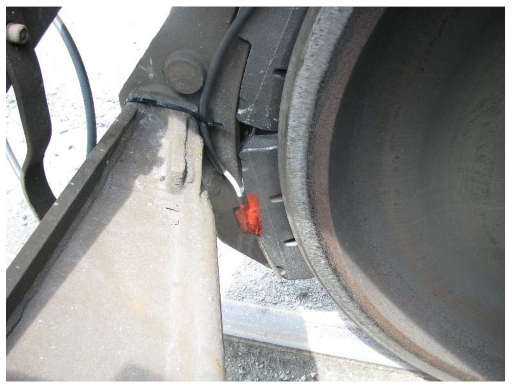
During the measurement campaign a single shoe of the central bogie was equipped with a temperature sensor. Preliminary tests were performed to verify that the temperature was uniformly distributed on the four blocks acting on each wheel. The temperature of the brake block was measured by means of a Pt1000 thermistor and a suitable signal conditioning circuit. During the monitoring system design and development stages, several laboratory tests were performed, comparing the measured values with those provided by an infrared thermometer, in order to calibrate the measurement system. A housing seat, near the part of the shoe fixed to the brake block holder, was obtained on the brake block, see Figure 2.
The diagnostic attachment points, employed during the periodic bench brake tests, were used to install the pressure sensors used to monitor the operating pressures of the wagon braking system. The adopted pressure sensors had a resolution of 7 mbar. The measurement campaign lasted a year, for a total monitored distance of about 30,000 km.
3. Thermal Model
An energetic approach, based on the thermal energy generated by the friction between the wheel and the shoes during braking operations, was used for the thermal investigation of the cast iron brake blocks. The main parameters for this type of analysis are the knowledge of the friction coefficient between the two contacting bodies, the geometry and material of the cast iron block, the pressure in the brake cylinder, and the geometry of the brake rigging, which determines the total rigging ratio. The wheel–shoe friction coefficient depends on the instantaneous speed of the vehicle and on the normal force acting on each shoe (contact pressure). In fact, due to the braking action, the blocks heat up, and this reduces the coefficient of friction between the wheel and the shoe. The mean values of the friction coefficient μ, used to build the model, were chosen in accordance with the literature and the technical data sheets provided by manufacturers of braking components [32], and an average wheel–shoe friction coefficient of 0.15 is assumed for the simulations described in this work.
Please note that the proposed model only computes the temperature field arising in the brake block, while the wheel temperature is not calculated, as the monitoring system does not include a temperature sensor able to measure the wheel temperature. Moreover, in order to calculate the wheel thermal field, accurate vehicle dynamics and wheel–rail contact models would be required, possibly accounting for adhesion drops in degraded conditions [33,34,35].
Each wheel of the monitored wagon is equipped with four cast iron shoes, for a total of 16 blocks per bogie. The contact angle between the single cast iron brake shoe and the wheel is 29.4°. With this value it is possible to calculate the contact surface between the two bodies, where the heat exchange takes place. The thermo-physical properties of the cast iron block installed on the Sggmrs wagon have similar values to those presented in the literature, therefore the values from the work by Vernersson [6], shown in Table 1, are considered in this paper.
The monitoring system samples the pressure of the central bogie brake cylinder at 1 Hz and saves it in the memory. The pressure value determines the braking condition, and to obtain an average value of the pressure signal pmean for the calculation of the thermal flow the integral mean value is used, calculated according to Equation (1), where p(t) is the instantaneous pressure, while tf and ti are, respectively, the time at the beginning and at the end of the braking maneuver.
Knowing the geometry of the brake cylinder (area Acylinder) and the rigging ratio of the braking system, it is possible to obtain the pressing force Fblock that each brake shoe exerts on the wheel during braking using Equations (2)–(4), following the prescriptions of the UIC 544-1 fiche [36]. In Equations (2)–(4), Fbogie is the sum of all pressing forces acting on the blocks installed on the bogie, Fcylinder is the force exerted on the brake cylinder, itot is the total multiplication rigging ratio, iII is the multiplication ratio after the central rigging, ηdyn is the efficiency of the brake rigging, Fs,rig is the is the counteracting force of the brake rigging regulator, Fs,cylinder is the brake cylinder spring return force, pcylinder is the brake cylinder pressure, and finally, Acylinder is the area of the brake cylinder. The multiplication ratio of the central rigging was determined from the rigging design and it is equal to 2, while the multiplication ratio after the central rigging is assumed equal to 4 according to the fiche prescriptions. Similarly, the brake cylinder spring return force and the regulator counteracting force are assumed equal to 1.5 and 2 kN, respectively, while the efficiency of the brake rigging is assumed equal to 0.83. Please note that in Equation (2), 16 is the total number of blocks of the bogie that are actuated by the brake cylinder, and the brake cylinder force is assumed to be uniformly distributed on the brake blocks, while the effect of inclination of the normal force acting on each shoe, is neglected.
The average friction force Ft,avg at the wheel–shoe interface is obtained from the product of the shoe normal force and the average friction coefficient , as shown in Equation (5).
The monitoring system includes a GPS sensor that provides information about current time, position, distance, and elevation. Using these data, it is possible to obtain the thermal energy Eth generated during braking according to Equation (6), where df is the running distance during braking operation and Dt is the time duration of the maneuver.
The heat flow Fth that is generated from the friction between the two bodies is obtained according to Equation (7), where Acontact is the surface of the block in contact with the wheel.
At this initial stage of the activity, the simple model briefly described above is developed to check the reliability of the monitoring system. However, an upgrade of the model is planned by combining a detailed multibody model of a single vehicle and a longitudinal train dynamics code, able to better simulate the vehicle dynamics behavior during braking operations [37,38,39,40].
4. FE Model
The thermal model of the brake block was realized with the FE code Ansys APDL. Figure 3 shows the developed model of the brake block, where the reduction of the mesh size close to the thermal sensor location can be noticed. The mesh is realized using the 20-nodes SOLID90 element, a specific element for transient thermal analysis with a single degree of freedom, i.e., the temperature, for each node. The whole model consists of a total of 21,076 nodes. The thermal flux, calculated according to Equation (5), is applied as a surface load on the area corresponding to the wheel–shoe contact surface. The load is applied for a time duration equal to duration of the monitored braking operation. At the end of the braking operation, the heat flux is removed to evaluate the evolution of the temperature in the area where the thermal sensor is applied. On the lateral surfaces of the brake block, which are in direct contact with the air flow, a convection coefficient equal to 10 W/m2 °C is applied, which ensures a good agreement with the literature [6]. The ambient temperature was assumed to be 10 °C, because the experimental test was performed in February.
5. Results
The FE model only considers a single brake block. Therefore, the portion of the total heat flow entering the block, calculated with Equation (7), must be determined prior to the simulation. The heat flow entering the block is calculated introducing a partitioning factor α, depending on the geometry of wheel and shoe and on the thermal effusivity of the contacting bodies, see Equations (8)–(10), in which is the contact surface, is the thermal conductivity, is the density, is the mass specific heat, and finally, subscripts and relate to the shoe and wheel, respectively.
The wheel and shoe contact surfaces are calculated according to Equations (11) and (12), in which Rw is the wheel radius, Hb is the block axial width, Lb is the block length and Nbw is the number of blocks per wheel as suggested by Haidari and Tehrani [41].
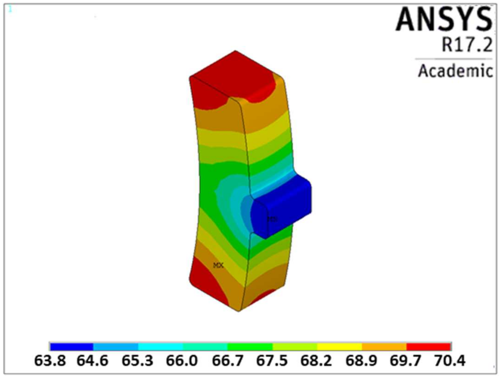
Figure 4 and Figure 5 show the results of the simulation of braking operation A, considering two different time steps. In fact, Figure 4 shows the brake block temperature field when the braking action ends, while Figure 5 shows the distribution of temperatures on the brake block when the maximum temperature is reached at the position where the temperature sensor is installed.
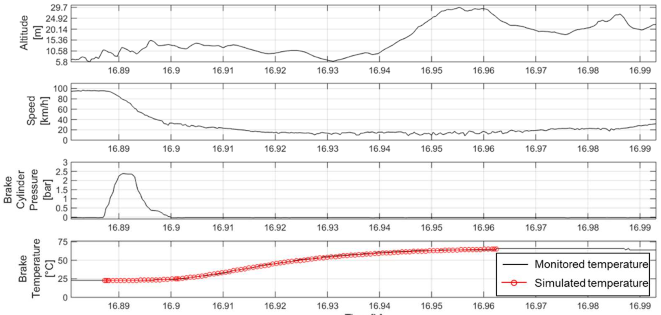
Figure 6 shows the altitude and speed of the vehicle, measured by the GPS sensor, the pressure on the brake cylinder, and the temperature of the brake block. The data were recorded during on track tests and are relative to braking operation A. The last plot of Figure 6 compares the trend of the brake block temperature obtained during the experimental test with the one obtained from the numerical model, and it shows a great agreement between the experimental records and the numerical predictions. In particular, the numerical model is able to correctly predict the trend of the temperature increase on the brake block due to the braking maneuver. Moreover, braking type A and B being very similar, the maximum temperature increases on the brake block at the end of the braking maneuver are very close to each other.
Figure 7, Figure 8 and Figure 9 show similar results for braking maneuver B, and even in this scenario the simulation results fit well with the trend of the real temperature of the cast iron brake block. Analyzing Figure 4 and Figure 7 it is evident the thermal gradient on the brake block due to the thermal inertia of the material. In fact, the block surface in contact with the wheel reaches much higher temperatures. Figure 5 and Figure 8 show the temperature of the brake block after the braking operation has been over for a significant amount of time; in fact, the material thermal inertia requires a certain amount of time to heat up the material block at the location where the thermal sensor is installed. Results show that the central part of the block reaches lower temperatures with respect to the edges, and this effect can be related to the prominence used to connect the block to the holder, which has a high thermal inertia.
The results computed by the numerical model verify the accuracy of the model and the method used for the evaluation of the thermal flux entering the railway block under braking conditions. Therefore, the developed thermal model can be considered a reliable tool for the estimation of the brake block temperature, which is a vital parameter for the monitoring unit to assess the proper working of the braking system. Simulations not shown in the paper were also carried out to quantify the effect of the convective heat exchange, proving that its weight is marginal with respect to the heat flow due to friction contact.
6. Conclusions
The paper deals with the investigation of the thermal behavior of a cast iron brake block during braking maneuvers by means of both experimental tests and FE analyses performed using the Ansys Mechanical APDL commercial software package. The numerical model was validated against the experimental data collected by a monitoring system developed by the research group from Politecnico di Torino during a test campaign in the context of the Cluster ITS Italy 2020 project for two different braking maneuvers. The monitoring system can detect the brake block temperature by means of a thermistor installed close to the brake block holder. The results of the model validation showed a good agreement between the experimental temperature and the temperature computed by the FE code at the location where the thermistor is installed. Therefore, the model can produce reliable outputs and can be used to choose the best location for the installation of the thermistor for monitoring purposes. In fact, the FE model allows to estimate the temperature at the wheel–shoe contact interface starting from the measurements of a temperature sensor installed in a different location.
In future upgrades, the numerical model can be improved to allow the investigation of the thermal behavior of not only the brake block but also of the wheel and axle-box, so that a better understanding of the relationship between the wheelset temperature and the wheel–shoe contact interface temperature can be obtained. Moreover, the code will be upgraded to consider different types of brake shoe material, including composite organic and sinter materials. Therefore, a new experimental campaign should be carried out to verify the model accuracy in the prediction of the brake shoe temperature for composite materials.
Author Contributions
Conceptualization, A.S. and N.Z.; methodology, N.Z.; software, M.A.; validation, A.S. and M.A.; writing—original draft preparation, M.A. and N.Z.; writing—review and editing, N.Z.; supervision, A.S. and N.Z.; project administration, A.S.; funding acquisition, A.S. All authors have read and agreed to the published version of the manuscript.
Funding
This research was funded by the Cluster ITS Italy 2020 project.
Institutional Review Board Statement
Not applicable.
Informed Consent Statement
Not applicable.
Data Availability Statement
Not applicable.
Acknowledgments
The authors wish to thank the intermodal transport company Ambrogio Trasporti S.p.a. for their support during the experimental campaign.
Conflicts of Interest
The authors declare no conflict of interest.
References
- Aimar, M.; Somà, A. Study and results of an onboard brake monitoring system for freight wagons. Proc. Inst. Mech. Eng. Part F J. Rail Rapid Transit. 2017, 232, 1277–1294. [Google Scholar] [CrossRef]
- Vaerst, M. Noise—Technical and Operational Aspects to be Considered When Retrofitting Existing Freight Cars with LL Brake Blocks. UIP Topical Committee Interoperability, 2015. Available online: https://www.google.com/url?sa=t&rct=j&q=&esrc=s&source=web&cd=&ved=2ahUKEwiexoaNnuXwAhW4AxAIHb0dD5UQFjAAegQIAhAF&url=https%3A%2F%2Fuiprail.org%2Fcontent%2Fuploads%2F2015%2F09%2F20150923-Interoperability-UIP-technical-note-on-operational-aspects-of-using-LL-brake-blocks_V1.pdf&usg=AOvVaw28jcN5AGDLAfy3mV5PLOgE (accessed on 28 April 2021).
- Usage Guidelines for Composite (LL) Brake Blocks (10th edition). International Union of Railways, 2013. Available online: https://www.google.com/url?sa=t&rct=j&q=&esrc=s&source=web&cd=&cad=rja&uact=8&ved=2ahUKEwjhvbDznuXwAhXBh_0HHW9pA0cQFjAAegQIBBAF&url=https%3A%2F%2Fuic.org%2FIMG%2Fpdf%2Fuic_usage_guidelines_for_composite_brake_blocks_ll_not-updated.pdf&usg=AOvVaw2ODb0ChKhYymCddBFBcYsK (accessed on 28 April 2021).
- Mańka, A.; Sitarz, M. Effects of a thermal load on the wheel/brake-block subsystem: The thermal conicity of railway wheels. Proc. Inst. Mech. Eng. Part F J. Rail Rapid Transit. 2016, 230, 193–205. [Google Scholar] [CrossRef]
- Teimourimanesh, S.; Lundén, R.; Vernersson, T. Braking capacity of railway wheels—State-of-the-art survey. In Proceedings of the 16th International Wheelset Congress, Cape Town, South Africa, 14–19 March 2010. [Google Scholar]
- Vernersson, T. Temperatures at railway tread braking. Part 2: Calibration and numerical examples. Proc. Inst. Mech. Eng. Part F J. Rail Rapid Transit. 2007, 221, 429–441. [Google Scholar] [CrossRef]
- Caprioli, S.; Ekberg, A. Numerical evaluation of the material response of a railway wheel under thermomechanical braking conditions. Wear 2014, 314, 181–188. [Google Scholar] [CrossRef]
- Fec, M.C.; Sehitoglu, H. Thermal-mechanical damage in railroad wheels due to hot spotting. Wear 1985, 102, 31–42. [Google Scholar] [CrossRef]
- Petersson, M. Noise-related roughness of railway wheel treads-full-scale testing of brake blocks. Proc. Inst. Mech. Eng. Part F J. Rail Rapid Transit. 2000, 214, 63–77. [Google Scholar] [CrossRef]
- Abbasi, S.; Teimourimanesh, S.; Vernersson, T.; Sellgren, U.; Olofsson, U.; Lundén, R. Temperature and thermoelastic instability at tread braking using cast iron friction material. Wear 2014, 314, 171–180. [Google Scholar] [CrossRef] [Green Version]
- Wasilewski, P. Experimental study on the effect of formulation modification on the properties of organic composite railway brake shoe. Wear 2017, 390–391, 283–294. [Google Scholar] [CrossRef]
- Wasilewski, P. Full-Scale Dynamometer Test of Composite Railway Brake Shoes—Study on the Effect of the Reinforcing Fibre Type. Acta Mech. et Autom. 2018, 12, 204–208. [Google Scholar] [CrossRef] [Green Version]
- Faccoli, M.; Ghidini, A.; Mazzù, A. Changes in the microstructure and mechanical properties of railway wheel steels as a result of the thermal load caused by shoe braking. Met. Mater. Trans. A 2019, 50, 1701–1714. [Google Scholar] [CrossRef]
- Srivastava, J.P.; Sarkar, P.K.; Ranjan, V. Effects of thermal load on wheel–rail contacts: A review. J. Therm. Stress. 2016, 39, 1389–1418. [Google Scholar] [CrossRef]
- Vakkalagadda, M.; Srivastava, D.; Mishra, A.; Racherla, V. Performance analyses of brake blocks used by Indian Railways. Wear 2015, 328–329, 64–76. [Google Scholar] [CrossRef]
- Vernersson, T.; Lunden, R.; Abbasi, S.; Olofsson, U. Wear of Railway brake block materials at elevated temperatures: Pin-on-disc experiments. In Proceedings of the Eurobrake 2012, Dresden, Germany, 16–18 April 2012. [Google Scholar]
- Vernersson, T. Thermally induced roughness of tread braked railway wheels. Wear 1999, 236, 106–116. [Google Scholar] [CrossRef]
- Petereson, M. Two-dimensional finite element simulation of the thermal problem at railway block braking. Proc. Inst. Mech. Eng. Part C J. Mech. Eng. Sci. 2002, 216, 259–273. [Google Scholar] [CrossRef]
- Thuresson, D. Influence of material properties on sliding contact braking applications. Wear 2004, 257, 451–460. [Google Scholar] [CrossRef]
- Békési, N.; Váradi, K. Contact Thermal Analysis and Wear Simulation of a Brake Block. Adv. Tribol. 2013, 2013, 1–7. [Google Scholar] [CrossRef]
- Vernersson, T.; Lundén, R. Wear of brake blocks for in-service conditions—Influence of the level of modelling. Wear 2014, 314, 125–131. [Google Scholar] [CrossRef]
- Walia, M.S.; Vernersson, T.; Lundén, R.; Blennow, F.; Meinel, M. Temperatures and wear at railway tread braking: Field experiments and simulations. Wear 2019, 440–441, 203086. [Google Scholar] [CrossRef]
- Ivanov, P.; Khudonogov, A.; Dulskiy, E.; Manuilov, N.; Khamnaeva, A.; Korsun, A.; Treskin, S. Study of the influence of the brake shoe temperature and wheel tread on braking effectiveness. J. Physics: Conf. Ser. 2020, 1614. [Google Scholar] [CrossRef]
- Cole, K.; Tarawneh, C.; Fuentes, A.; Wilson, B.; Navarro, L. Thermal models of railroad wheels and bearings. Int. J. Heat Mass Transf. 2010, 53, 1636–1645. [Google Scholar] [CrossRef] [Green Version]
- Bosso, N.; Gugliotta, A.; Magelli, M.; Zampieri, N. Monitoring of railway freight vehicles using onboard systems. Procedia Struct. Integr. 2019, 24, 692–705. [Google Scholar] [CrossRef]
- Bosso, N.; Magelli, M.; Zampieri, N. Validation of a brake monitoring system using a multi-axle roller-rig. In Computers in Railways XVII: Railway Engineering Design and Operation, Proceedings of the 17th International Conference on Railway Engineering Design & Operation, Wessex, UK, 1–3 July 2020; Passerini, G., Mera, J.M., Takagi, R., Eds.; WIT Press: Southampton, UK, 2020; Volume 199, pp. 151–161. [Google Scholar]
- Bosso, N.; Magelli, M.; Zampieri, N. Calibration and development of a multi-axis roller bench for monitoring the braking system of a railway vehicle. Ingegneria Ferroviaria 2020, 75, 501–523. [Google Scholar]
- Bosso, N.; Gugliotta, A.; Zampieri, N. Design and testing of an innovative monitoring system for railway vehicles. Proc. Inst. Mech. Eng. Part F J. Rail Rapid Transit. 2018, 232, 445–460. [Google Scholar] [CrossRef]
- Somà, A.; Aimar, M.; Zanardelli, A. Experimental data measured with an on Board Unit for condition monitoring of freight wagons. Ingegneria Ferroviaria 2017, 72, 547–567. [Google Scholar]
- Somà, A.; Aimar, M. Study and design of a wireless monitoring device for intermodal freight wagons. In Proceedings of the Dynamics of Vehicles on Roads and Tracks, Rockhampton, QLD, Australia, 14–17 August 2017; pp. 1051–1058. [Google Scholar]
- Aimar, M.; Malvindi, A. Simulazione FEM del Comportamento Termico dell’Impianto Frenante di un Carro Merci dotato di Ceppi in Ghisa. In Proceedings of the AIAS—Associazione Italiana per l’Analisi delle Sollecitazioni- 46° Convegno Nazionale, Università Degli Studi Di Pisa, Pisa, Italy, 6–9 September 2017. [Google Scholar]
- Vineesh, K.; Vakkalagadda, M.; Srivastava, D.; Misra, A.; Racherla, V. Analyses of Temperatures in Locomotive Wheels Fitted with Cast iron and Composite Brake Blocks. In Proceedings of the Indian National Conference on Applied Mechanics IIT, Delhi, India, 13–15 July 2015. [Google Scholar]
- Bosso, N.; Soma, A.; Gugliotta, A. Introduction of a wheel-rail and wheel-roller contact model for independent wheels in a multibody code. In Proceedings of the ASME/IEEE Joint Railroad Conference, Washington, DC, USA, 23–25 April 2002; pp. 151–159. [Google Scholar]
- Bosso, N.; Gugliotta, A.; Soma, A. Dynamic Behavior of a Railway Wheelset on a Roller Rig versus Tangent Track. Shock. Vib. 2004, 11, 467–492. [Google Scholar] [CrossRef]
- Bosso, N.; Gugliotta, A.; Magelli, M.; Oresta, I.F.; Zampieri, N. Study of wheel-rail adhesion during braking maneuvers. Procedia Struct. Integr. 2019, 24, 680–691. [Google Scholar] [CrossRef]
- UIC 544-1, Brakes—Braking Performance, 2014. Available online: https://global.ihs.com/doc_detail.cfm?&input_doc_number=&input_doc_title=&document_name=UIC%20544%2D1%20%28E%29&item_s_key=00455592&item_key_date=850231&origin=DSSC (accessed on 28 April 2021).
- Bosso, N.; Gugliotta, A.; Soma, A. Multibody simulation of a freight bogie with friction dampers. In Proceedings of the ASME/IEEE Joint Railroad Conference, Washington, DC, USA, 23–25 April 2002; pp. 47–56. [Google Scholar]
- Bosso, N.; Magelli, M.; Zampieri, N. Long Train Dynamic Simulation by Means of A New In-House Code. In Proceedings of the Computers in Railways XVII; WIT Press Ltd.: Cambridge, MA, USA, 2020; pp. 249–259. [Google Scholar]
- Bosso, N.; Magelli, M.; Bartoli, L.R.; Zampieri, N. The influence of resistant force equations and coupling system on long train dynamics simulations. Proc. Inst. Mech. Eng. Part F J. Rail Rapid Transit. 2021. [Google Scholar] [CrossRef]
- Bosso, N.; Magelli, M.; Zampieri, N. Development and validation of a new code for longitudinal train dynamics simulation. Proc. Inst. Mech. Eng. Part F J. Rail Rapid Transit. 2021, 235, 286–299. [Google Scholar] [CrossRef]
- Haidari, A.; Tehrani, P.H. Thermal load effects on fatigue life of a cracked railway wheel. Lat. Am. J. Solids Struct. 2015, 12, 1144–1157. [Google Scholar] [CrossRef] [Green Version]
Figure 1.
Scheme of the monitoring unit.

Figure 2.
Brake block with temperature sensor.

Figure 3.
Mesh of the brake pad obtained in Ansys ADPL.

Figure 4.
Braking maneuver A—Temperature of the brake block at the end of the brake maneuver.

Figure 5.
Braking maneuver A—Temperature of the brake block when the maximum temperature is reached at the position where the sensor is installed.
Figure 5.
Braking maneuver A—Temperature of the brake block when the maximum temperature is reached at the position where the sensor is installed.

Figure 6.
Braking maneuver A—Comparison of measured and simulated temperature of the brake block at the position where the sensor is installed.
Figure 6.
Braking maneuver A—Comparison of measured and simulated temperature of the brake block at the position where the sensor is installed.

Figure 7.
Braking maneuver B—Temperature of the brake block at the end of the brake maneuver.

Figure 8.
Braking maneuver B—Temperature of the brake block when the maximum temperature is reached at the position where the sensor is installed.
Figure 8.
Braking maneuver B—Temperature of the brake block when the maximum temperature is reached at the position where the sensor is installed.

Figure 9.
Braking maneuver B—comparison of measured and simulated temperature of the brake block at the position where the sensor is installed.
Figure 9.
Braking maneuver B—comparison of measured and simulated temperature of the brake block at the position where the sensor is installed.


Table 1.
Thermo-physical properties of the cast iron block.
| Physical Quantity | Value |
|---|---|
| Thermal conductivity, k—[W/m K] | 48 |
| Density, ρ—[kg/m3] | 7100 |
| Heat capacity, c—[J/kg K] | 520 |
Table 2.
Input data for the finite element (FE) model.
| Braking Maneuver | Braking Distance [m] | Initial Speed [km/h] | Final Speed [km/h] | Initial Block Temperature [°C] | Mean Pressure of the Brake Cylinder [bar] | Braking Duration [s] | Time Elapsed from Brake Activation to Reaching Maximum Temperature [s] |
|---|---|---|---|---|---|---|---|
| A | 786 | 95 | 33 | 23 | 1.12 | 47 | 271 |
| B | 713 | 93 | 23 | 37 | 1.20 | 46 | 220 |
Publisher’s Note: MDPI stays neutral with regard to jurisdictional claims in published maps and institutional affiliations. |
© 2021 by the authors. Licensee MDPI, Basel, Switzerland. This article is an open access article distributed under the terms and conditions of the Creative Commons Attribution (CC BY) license (https://creativecommons.org/licenses/by/4.0/).
Share and Cite
MDPI and ACS Style
Somà, A.; Aimar, M.; Zampieri, N. Simulation of the Thermal Behavior of Cast Iron Brake Block during Braking Maneuvers. Appl. Sci. 2021, 11, 5010. https://doi.org/10.3390/app11115010
AMA Style
Somà A, Aimar M, Zampieri N. Simulation of the Thermal Behavior of Cast Iron Brake Block during Braking Maneuvers. Applied Sciences. 2021; 11(11):5010. https://doi.org/10.3390/app11115010
Chicago/Turabian StyleSomà, Aurelio, Marco Aimar, and Nicolò Zampieri. 2021. "Simulation of the Thermal Behavior of Cast Iron Brake Block during Braking Maneuvers" Applied Sciences 11, no. 11: 5010. https://doi.org/10.3390/app11115010
Note that from the first issue of 2016, this journal uses article numbers instead of page numbers. See further details here.