
WAAM-Fabricated Laminated Metal Composites

1
Institute for Metal and Composite Structures, Hamburg University of Technology, Denickestr. 17, 21073 Hamburg, Germany
2
Institute for Ship Structural Design and Analysis, Hamburg University of Technology, Am Schwarzenberg Campus 4 C, 21073 Hamburg, Germany
*
Author to whom correspondence should be addressed.
Metals 2021, 11(12), 1948; https://doi.org/10.3390/met11121948
Submission received: 13 October 2021
/
Revised: 23 November 2021
/
Accepted: 29 November 2021
/
Published: 2 December 2021
(This article belongs to the Special Issue Additive Manufacturing of Metallic Materials: Structures, Properties, and Methodologies)
Abstract
:Laminated metal composites are a promising design since the hybrid design enables superior and tailorable material properties compared with bulk material. The article introduces for the first time, laminated metal composites consisting of multiple bilayers of alternating layers of ductile and high-strength steel processed by wire arc additive manufacturing (WAAM). The layup of the laminated metal composites is built up by alternating deposits made of ductile steel and high-strength steel type wires. Governing parameters in the fabrication process affecting the material properties, such as dilution, are discussed. Enhanced material properties of the laminated metal composites fabricated by WAAM are investigated under static tensile, impact and tension-tension high-cycle-fatigue loading and compared to the relating homogenous weld metal. Potential reasons for the retardation of crack propagation in laminated metal composites fabricated by WAAM compared to findings in roll-bonded laminated metal composites are discussed. WAAM is conducted by a collaborative robot providing a high level of flexibility in respect to geometry and scalability. Tailorability of material properties through WAAM-fabricated laminated metal composites adds an important layer of flexibility which has not been explored yet.
1. Introduction
Laminated metal composites (LMCs) are a promising design since the hybrid design enables superior and tailorable material properties compared with bulk material. Various methods exist to produce LMCs with single layer thicknesses in the macroscale, such as rolling and pressing, deposition and spraying. Only very limited literature exists about LMCs fabricated by arc welding based additive manufacturing, a direct energy deposition (DED) technique [1] using a collaborative robot. In a recent study, a functionally graded material (FGM) consisting of carbon-manganese steel and duplex stainless steel fabricated by WAAM was explored [2]. The study presented herein introduces, for the first time, LMCs consisting of multiple bilayers of alternating layers of two materials processed by wire arc additive manufacturing (WAAM). Hence, the LMCs fabricated by WAAM are also referred to as WAAM LMCs herein. Wire arc additive manufacturing provides multiple advantages in respect to flexibility (a) to build-up structures of individual geometry, (b) to not be limited by size (scalability), (c) to build in situ and (d) to build a structure without discrete joints. Particularly the last point is of interest in regard to fatigue resistance of structures. Most of the fatigue defects arise in joints [3], hence a method which avoids joints could be of high value in respect to reducing maintenance costs of, e.g., civil infrastructure.
The enhanced mechanical properties of steel-based LMCs manufactured by rolling and pressing are an improved fracture strain, increased tensile strength, toughness and better fatigue resistance compared to the homogenous weld metal material [4,5,6,7]. The literature names reasons for the enhanced material properties of LMCs manufactured by rolling and pressing compared with homogenous weld metal materials. On the one hand, delamination is seen as reason for the improved mechanical properties [4,5,6,7]. On the other hand, a high interface toughness which suppresses delamination in LMCs and enables load transfer between ductile and brittle layers of the laminate [8,9,10], is argued to be the key parameter. Hence, in this context, this article provides insights into section build-up, material properties and occurrence of delaminations of WAAM LMCs when exposed to static, impact or fatigue loading. The objectives of the study presented herein are to provide insights into the fabrication of laminated metal composites by WAAM, to investigate parameters affecting the material parameters of WAAM LMCs and to provide information on the failure mechanisms of WAAM LMCs.
2. State-of-the-Art
While WAAM LMCs have not been tested yet in Charpy V-notch tests, there are some findings gained with LMCs fabricated by different methods, such as rolling and pressing. Wadsworth et al. [4] compare the notch impact energy of an ARB-fabricated 12-layer metal composite, which consists of a ductile AISI-100 steel and an ultra-high carbon (UHC) AISI-52100 rolled steel, with the notch impact energy of its components. The LMC shows a higher notch impact energy by a factor of about 3.5 compared to the monolithic UHC-steel and by a factor of 1.5 compared to the monolithic ductile steel. The maximum toughness of the metal laminate is already achieved at a temperature of about T = −100 °C, while the respective maxima for mild steel and high-strength UHC are reached at about T = −25 °C and T = 100 °C, respectively. The authors explain the improved notch impact energy by notch blunting due to delaminations along the interfaces within the composite laminate. Further, the authors indicate that primarily the existence of interfaces of the ARB-fabricated laminate enable high impact values through crack deviation and notch blunting and the interleaf material being of secondary importance. This finding is backed up by laminate tests with UHC/UHC laminates.
Carreño et al. [5] investigated seven-layer-LMCs manufactured by roll-bonding at 650 °C. The notch impact energy of a seven-layer laminate consisting of a ductile steel and a UHC-steel is tested in crack arrestor orientation. The authors identify delamination, controlled by interface bonding, to play a key role for the deflection of the crack, absorbing energy and essentially nucleation of a new crack in the next material layer. The impact energy of the LMC is marginally larger than of the mild steel.
Koseki et al. [8] found improved combinations of strength and ductility as well as excellent deformation behavior under high-strain-rate deformation in roll-bonded LMCs compared with existing monolithic steels. The LMCs consist of a high-strength martensitic X46Cr13-steel (AISI 420) and a ductile X5CrNi18-10 steel (AISI 304). One outcome of the study is that to achieve both strength and ductility an increased interfacial toughness between the layers and a decreased thickness of the brittle steel is required.
There is some knowledge about the fatigue properties of LMCs with layer thicknesses in the micrometer range. Kümmel et al. [11] investigated rollbonded thin-layered LMCs (layer thickness 500 nm) consisting of alternating layers of commercial pure aluminum AA1050A and aluminum alloy subjected to fatigue loading. Bloyer et al. [12] studied the fatigue crack propagation behavior of ductile/brittle laminated niobium (Nb) reinforced niobium aluminide (Nb3Al) intermetallic-matrix composites. The authors explain that superior properties of the laminates in crack arrestor orientation result from intrinsic toughening due to trapping at, and crack renucleation across, the Nb layers and from extrinsic shielding from extensive crack bridging by intact Nb layers in the crack wake. The fatigue behavior of WAAM-fabricated LMCs has not been discussed or quantified yet.
The broad literature body of WAAM-fabricated materials also includes studies of metals other than steel. Wang et al. [13] provided interesting insights into material properties, such as average strength, ductility and fatigue strength of WAAM-fabricated titanium alloy (Ti-6Al-4V) components.
3. Materials and Methods
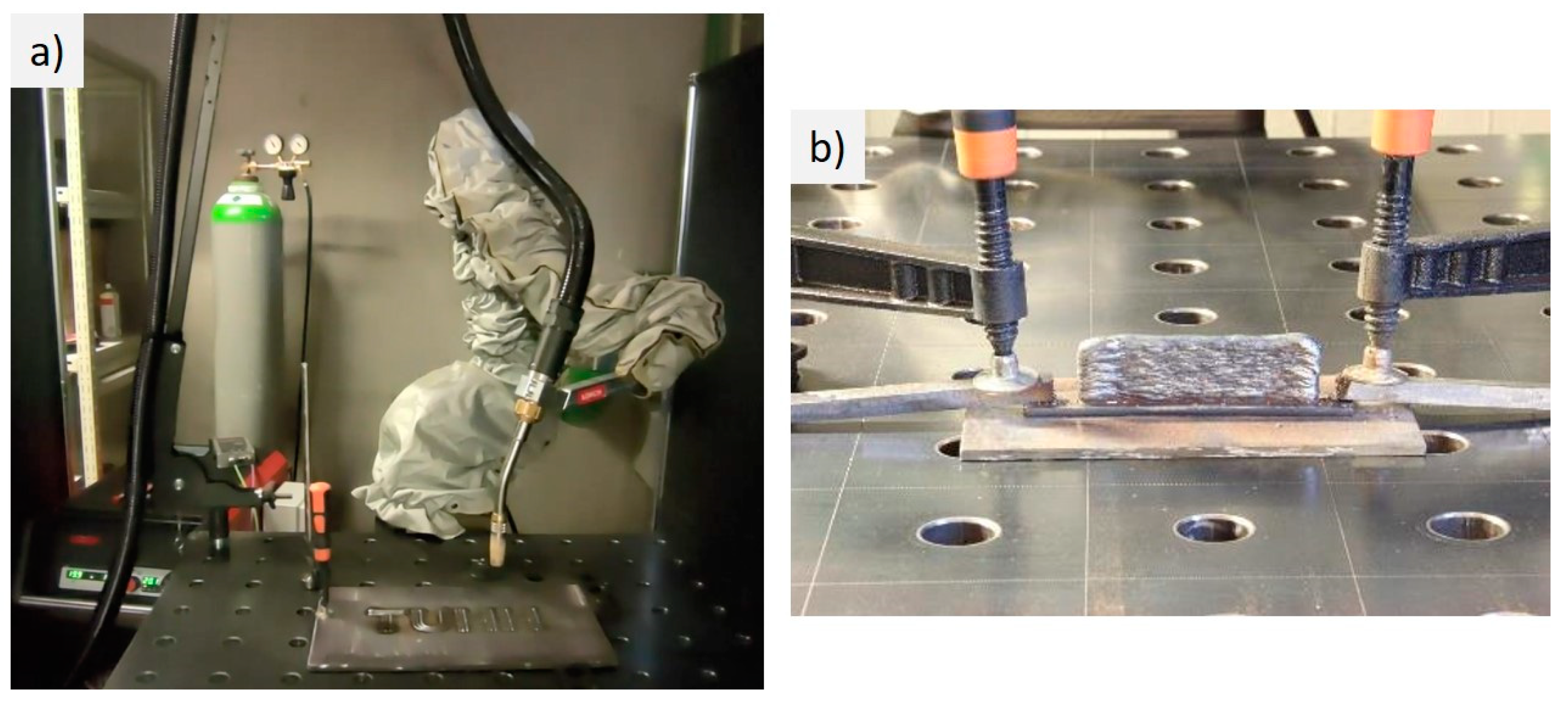
The WAAM LMC is fabricated by a collaborative operative robot (Universal Robot UR10e, Universal Robots, Odense, Denmark) guiding the welding equipment (Lorch S5 Speedpuls XT, Lorch Schweisstechnik GmbH, Auenwald, Germany) which allows highly precise and reproducible welds, as shown in Figure 1. The robot arm is mounted on a quadratic steel table which provides a plane working surface.
For the WAAM-fabricated LMC, two different weld materials are used, a 1-mm-diameter ductile steel wire, hereafter named SG2 (EMK 6 D, Böhler, material No. 1.5125) and a 1mm-diameter high-strength steel wire, hereafter named X90 (DT-X90, DRATEC GmbH, Krefeld, Germany, Material No. 1.6834). The filler wires SG2 and X90 are identified by EN ISO designations and the chemical compositions of each wire are provided in Table 1. The LMC presented herein is built up by alternating deposits made of ductile steel and high-strength steel type wires. The WAAM LMC is built up onto a steel substrate (S355), as shown in Figure 1.
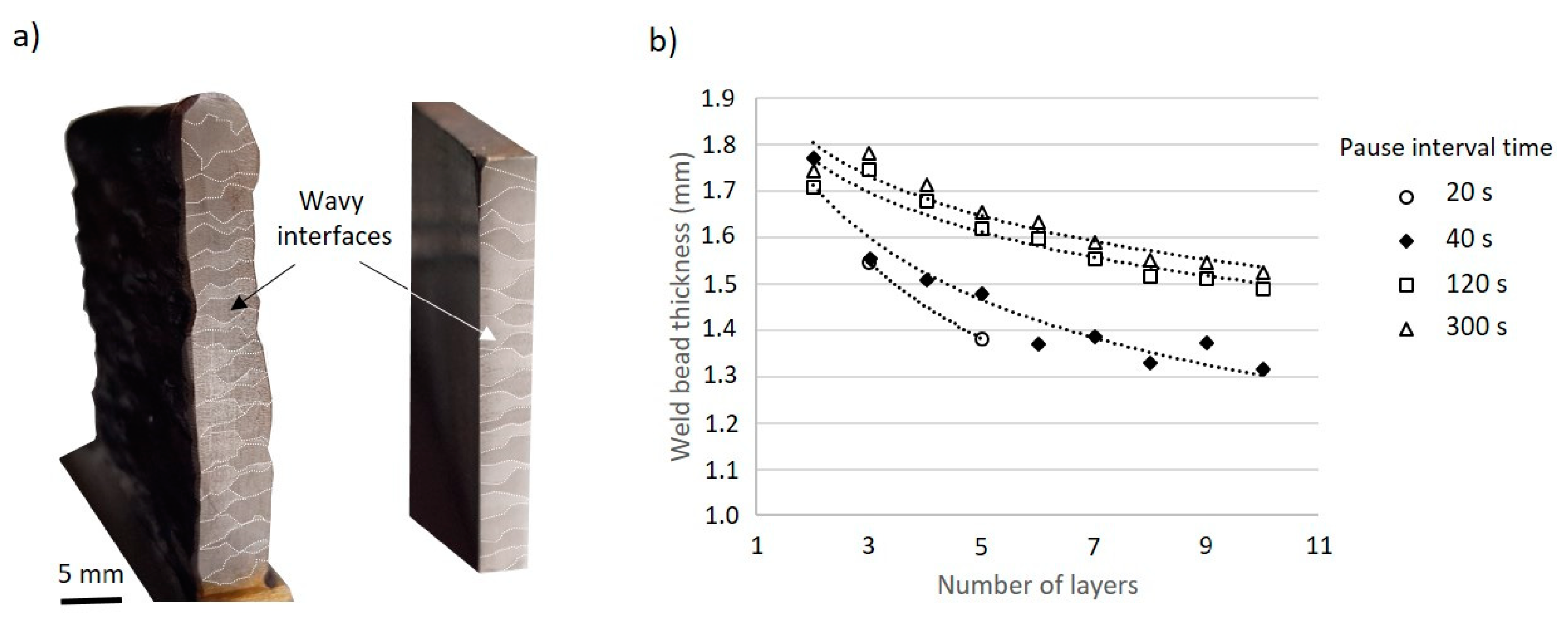
The layup of the WAAM LMC is governed by various process parameters, among others, the interpass temperature which affects the weld bead thickness. The interpass temperature is higher when the pause time, which is the time interval before the next weld layer is set, becomes shorter. There is a significant incremental reduction of the weld bead thickness in dependence of pause time and number of welds, as shown in Figure 2. A defined pause time controls the interpass temperature which directly affects the weld geometry and flowability of the weld. In this study, the initially defined weld height is h = 1.75 mm. The welds are set on top of each other and the weld bead thickness is measured after cooling by means of a Vernier caliper. The diagram in Figure 2 shows that the measured weld bead thickness decreases with increasing number of layers. Figure 2 (left) shows the section of the WAAM LMC as manufactured as well as cut and polished for fatigue testing. The cross section shows distinguishable alternating weld layers of ductile and high-strength steel. The thickness of the weld layer varies and wavy sharp interfaces of the weld layers are visible, as annotated in Figure 2. The interpass temperature not only affects the weld bead thickness, moreover, it also affects the dilution between SG2 and X90. The decreasing weld bead thickness with subsequent deposition of weld bead on top of each layer implies an increase in dilution between the two dissimilar deposits.
A pause time between tP = 40 s and tP = 120 s leads to meaningful data. At small pause times of tP = 20 s or less, the substrate plate deforms because of high energy input, thermally induced stresses in weld and substrate plate essentially causing weld defects. A pause time of 300 s results in a weld bead thickness which corresponds well with the weld bead thickness created by a pause time of 120 s, hence it is uneconomical. A reduced pause time results in a smaller weld bead thickness. The incremental change of the weld bead thickness with increasing number of layers is larger between the first and fifth weld layer, however, it eventually approaches a final weld bead thickness of about 1.3 mm using a pause time of 60 s.
Maintaining a constant current throughout the welding process is seen as crucial for receiving reproducible weld beads and a constant welding procedure. The contact-tip-to-work-distance (CTWD) is found to be a key parameter in tailoring weld bead geometries and is itself governed by welding parameters, e.g., the amperage. A suitable set of those parameters is determined and used throughout testing, as summarized in Table 2. Abbreviations are explained below the table.
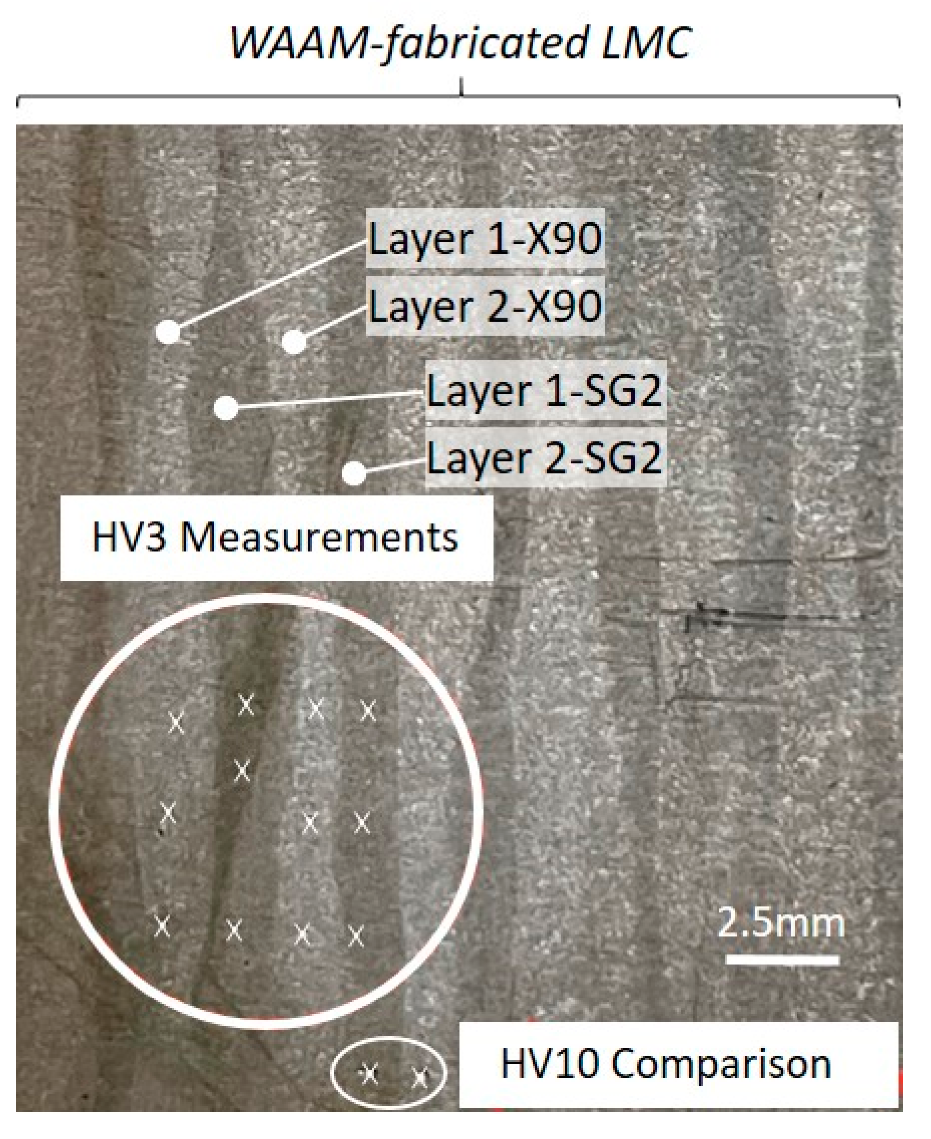
Table 3 presents the measured Vickers hardness (HV3) of the WAAM-fabricated LMC at three different equidistant measurement positions in the middle of a weld layer, as shown in Figure 3. Two layers of each material are measured for comparison. Interestingly, the observed hardness is almost identical for both steel types. The hardness corresponding to high-strength steel is about 188.65 (HV3), and the hardness of the mild steel is about 179.65 (HV3). The mechanical properties of the LMC are strongly influenced by the dilution between the unalloyed SG2 and X90 weld beads causing the hardness of both SG2 and X90 steel to fall in the same range of hardness. The applied welding heat input causes a strong dilution of alloy elements especially in the X90 beads and results in a significant decrease in hardness. HV10 measurements are conducted for validation reasons. The HV10 measurements confirm the HV3 measurements.
The results of the hardness measurements are subsequently compared to tensile test results (presented in Section 4.1), which describe the macroscopic stress–strain behavior of the two steels and the WAAM LMC, as shown in Table 4.
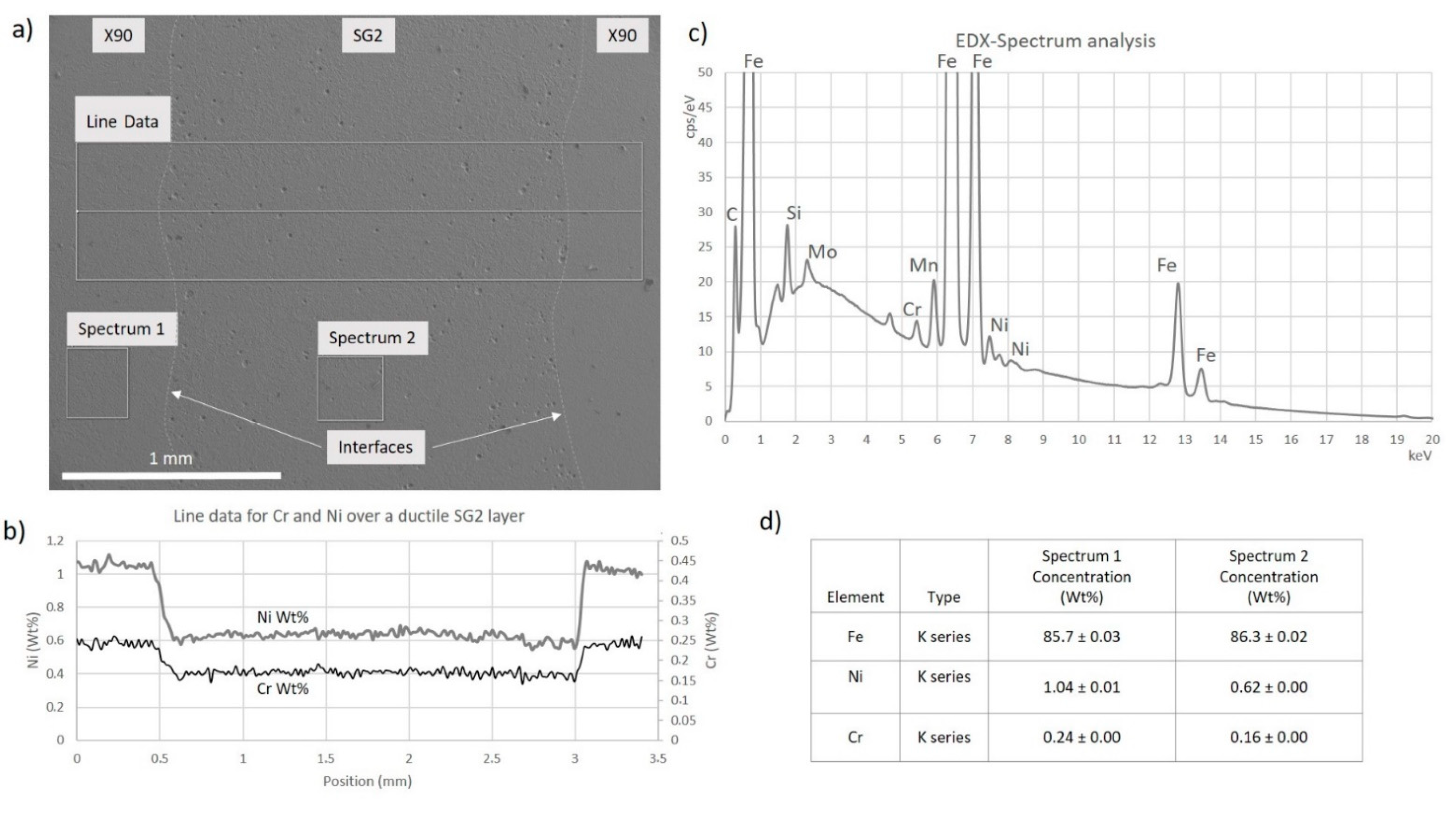
Figure 4 provides information regarding the extent of dilution by EDX-spectrum analysis. Figure 4a shows the SEM scan of a part of the WAAM layup with a SG2 layer in the center and X90 layers on both sides, as annotated. A line plot runs across the three layers cutting the interfaces, which are also annotated. The line plots in Figure 4b show the nickel (Ni) and the chromium (Cr) distribution across the interfaces of the laminate. According to the manufacturer, the Ni content of the X90 and SG2 is 2.0 wt% and 0 wt%, respectively, as listed in Table 1. However, dilution causes the concentration in the X90 layers to drop to 1.04 wt% while the Ni-concentration increases in the SG2 layer from 0 to 0.62 wt%. Further, according to the manufacturer, the Cr content of the X90 and SG2 is 0.3 wt% and 0 wt%, respectively. However, dilution causes the Cr-concentration in the X90 layers to drop to 0.24 wt% while the concentration increases in the SG2 layer from 0 to 0.16 wt%. It is concluded that significant dilution is identified which balances the hardness in this study and changes the material properties of the WAAM LMC. Figure 4c shows the EDX-spectrum analysis and Figure 4d lists the concentrations of Ni and Cr, as measured in spectrum 1 and spectrum 2 (see Figure 4a).
4. Results
This study includes static tension tests, Charpy V-notch tests and fatigue tests, in order to better understand the material properties, physical behavior and failure mode of WAAM-fabricated LMCs.
4.1. Static Tension Test
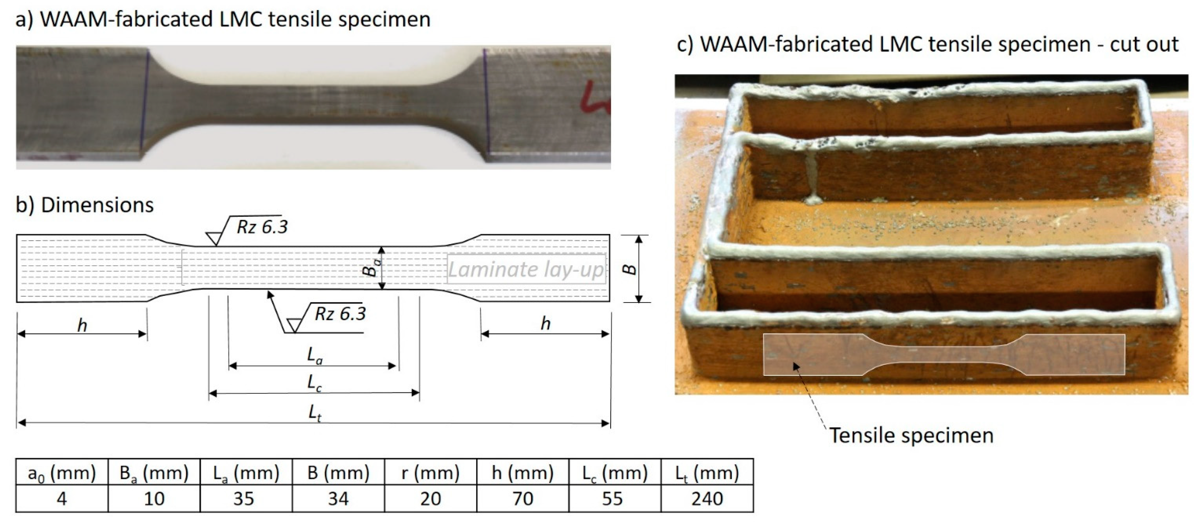
The specimen geometry for the static tension tests follows the DIN 50125 [16]. The specimen length is 240 mm. The WAAM-fabricated specimen originally has an uneven surface; hence, it is cut and polished to a thickness of 4 mm. EDM cutting und CNC-milling are used to cut out the dog bone specimen form. The reduced cross-section height of the dog bone specimen is 10 mm and has about seven layers, as shown in Figure 5. The specimen is cut out of the built WAAM-layup as shown in Figure 5c. The WAAM specimen out of ductile steel (SG2) and out of high-strength steel (X90), respectively, as well as the WAAM-fabricated LMC after the static test, are shown in Figure 6.
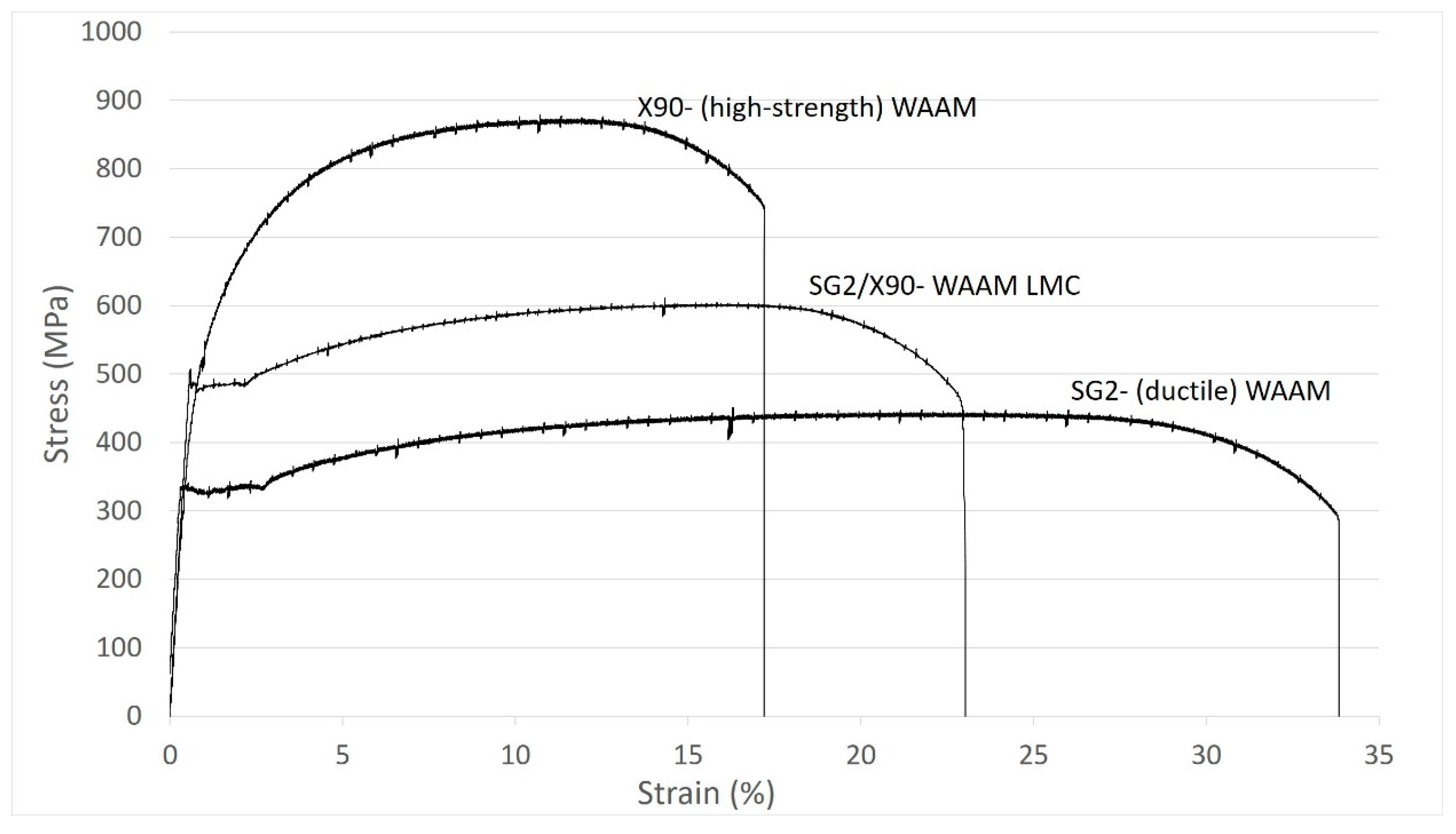
The hydraulic tension machine (Schenck PC400M; Schenck Technologie- und Industriepark, Darmstadt, Germany) is used for the static tension tests. Tension loading is applied displacement with controlled increasing of the displacement constantly by 0.03 mm/s. Yield strength, elastic strain, tensile strength and fracture strain are the parameters measured. The stress–strain curves assessed are shown in Figure 7.
Obviously, both steel materials, the ductile SG2 WAAM material and the high-strength X90 WAAM material, show the expected different behavior. While the ductile SG2 shows a fracture strain of 34%, the high-strength X90 only has a fracture strain of 17.5%. The ductile SG2 has a pronounced yielding and hardening, with yield strength of about 330 MPa and tensile strength of 440 MPa, while the high-strength X90 has no yielding and a tensile strength of 870 MPa. The WAAM-fabricated LMC has a fracture strain of 23%, a pronounced yield strength of 490 MPa and a tensile strength of 600 MPa. Since the laminate consists of 50% ductile and 50% high-strength steel, the rule of mixture would result in a yield strength of 665 MPa and a fracture strain of 25%. However, the material properties are much more dependent on dilution, as discussed in Section 3.
Table 5 lists the mechanical properties of the filler wires used for WAAM-fabricating the LMC. In respect to the yield strength, the difference between manufacturer information and measured results is provided. Since the high-strength steel (X90) does not show a yield strength plateau, the offset yield strength (Rp0.2) is assessed at 0.2% offset strain.
Overall, the measured tensile strength by using the homogenous WAAM specimen is larger than the tensile strength average estimated from Vickers hardness tests using the WAAM LMC (Table 4). Accounting for the offset yield strength of high-strength steel, the measured yield strength matches the yield strength average estimated from the Vickers hardness tests quite well.
4.2. Charpy V-Notch Impact Test
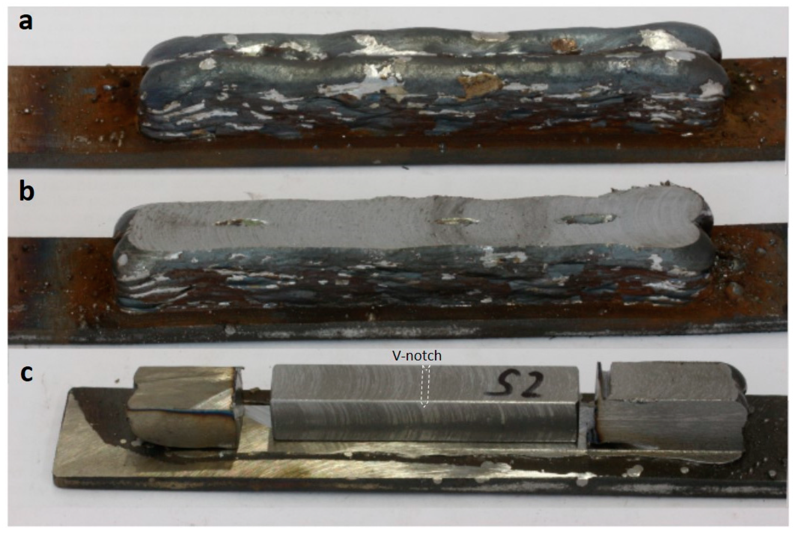
The specimen geometry is defined by DIN EN ISO 148-1 [17]. The specimen length is 55 mm, and the square cross section has a side length of 10 mm. The specimen geometry is produced in two steps, first the WAAM processing and second the post-weld EDM cutting and sanding [18]. The processing steps are shown in Figure 8: (a) the WAAM-fabricated LMC specimen, (b) the top surface preparation and (c) the V-notch sample completely cut from the substrate plate and polished with the final measures according to DIN EN ISO 148-1 [17]. The location of the V-notch is in crack arrestor orientation and is annotated in Figure 8c. Typically, Charpy V-notch testing is conducted at different temperatures. However, in this test series the temperature is held constant at room temperature (20 °C).
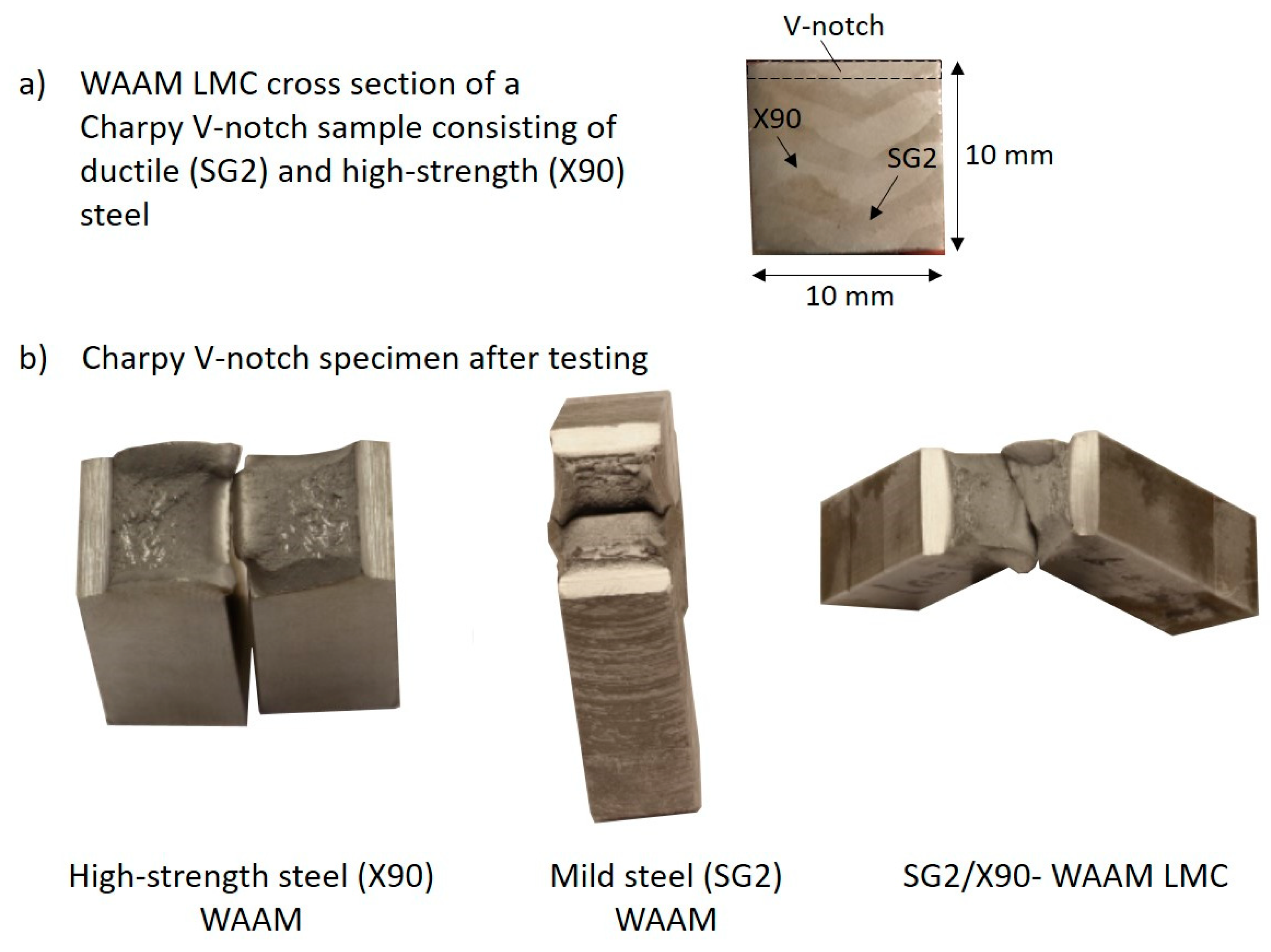
Six Charpy V-notch WAAM samples fabricated out of ductile steel (SG2), six Charpy V-notch WAAM samples fabricated out of high-strength steel (X90) and three Charpy V-notch WAAM samples fabricated out of SG2/X90-WAAM LMC are compared in this test series. Figure 9a shows the cross section of the Charpy V-notch sample fabricated out of WAAM LMC. The deformed Charpy V-notch samples out of high-strength (X90) WAAM, ductile (SG2) WAAM and the SG2/X90-WAAM LMC are shown in Figure 9b.
While the Charpy V-notch test splits the high-strength WAAM specimen into two parts, the ductile WAAM and the WAAM LMC specimen are still one piece. The high-strength and the ductile WAAM V-notch specimen fracture along the symmetry plane. However, the WAAM LMC specimen slightly torques during the deformation process.
Table 6 provides the energy values from Charpy V-notch testing. As expected, the homogenous high-strength WAAM samples respond brittlely, and show on average a reduced toughness of 62 J, with a ductile fracture percentage of 64%. The homogenous ductile WAAM samples show an average of about 154 J. The WAAM LMC reaches an average toughness of 144 J with a ductile fracture percentage of 81%, hence very close to the homogenous ductile WAAM samples with a ductile fracture percentage of 90%. Typically, in Charpy V-notch samples, the energy is found to be proportional to the yield strength ratio [19], which is not confirmed herein from studying WAAM-fabricated steel samples.
Samples from the Charpy V-notch WAAM LMC are prepared for microscopy, as shown in Figure 10. The samples are sawed out of the specimen and embedded in epoxy with copper content. The specimens are sanded beginning with 180 grit up to 2500 grit on rotating plates with water cooling and then with 4000 grit on a Tegramin-30 (Struers GmbH, Willich, Germany), and then polished in two steps. The first polishing step is done by using a 3 μ-diamond suspension, the second polishing step is done by an OP-S suspension (0.04 μ), where the OP-S content is mixed at a ratio of 1:2 with ethanol, cleansed by ethanol, treated in an ultrasound bath for about one minute, and finally cleaned with isopropanol and dried.
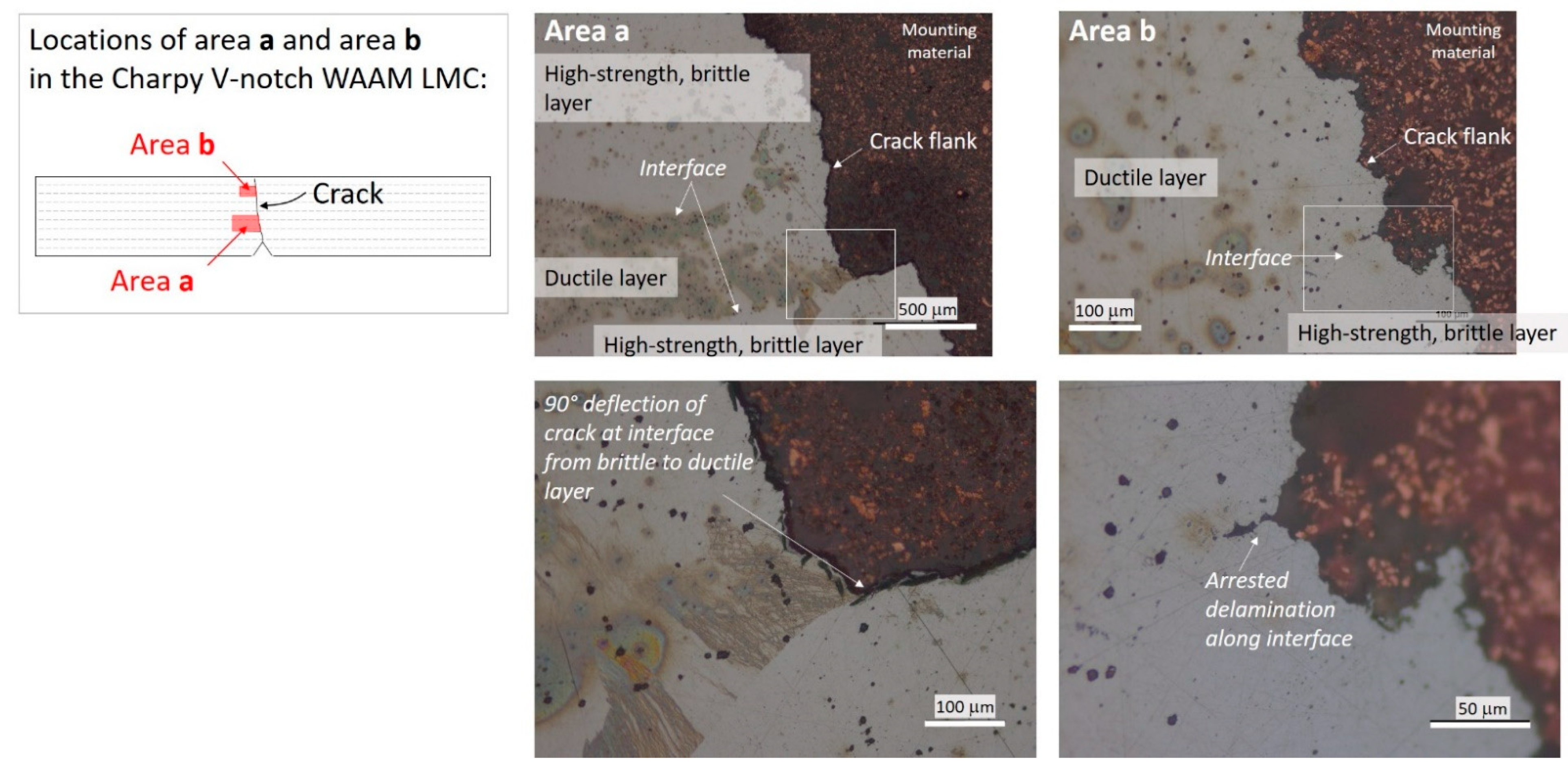
While the crack in the homogenous WAAM specimen cuts straight from the notch through the specimen, the dynamic fracture in the WAAM LMC is rather stair-stepped, as shown in area a (Figure 10). The location of area a is provided in the schematic sketch in Figure 10. The crack progression in area a is explained as follows: The crack in area a is blunted at the interface connecting the high-strength with the ductile layer. The crack diverts, runs along the interface causing delamination. Crack diversion and delamination consume fracture energy which essentially drops below the interface toughness. A crack then nucleates and initiates into the ductile layer leaving no residual delamination at the interface, as shown in Figure 10. Area b shows a similar interface between the high-strength and the ductile layer and a small crack along the interface is noticed. Apparently, delamination initiates here before the fracture energy drops below the interface toughness followed by crack nucleation into the ductile material layer.
4.3. Fatigue Test
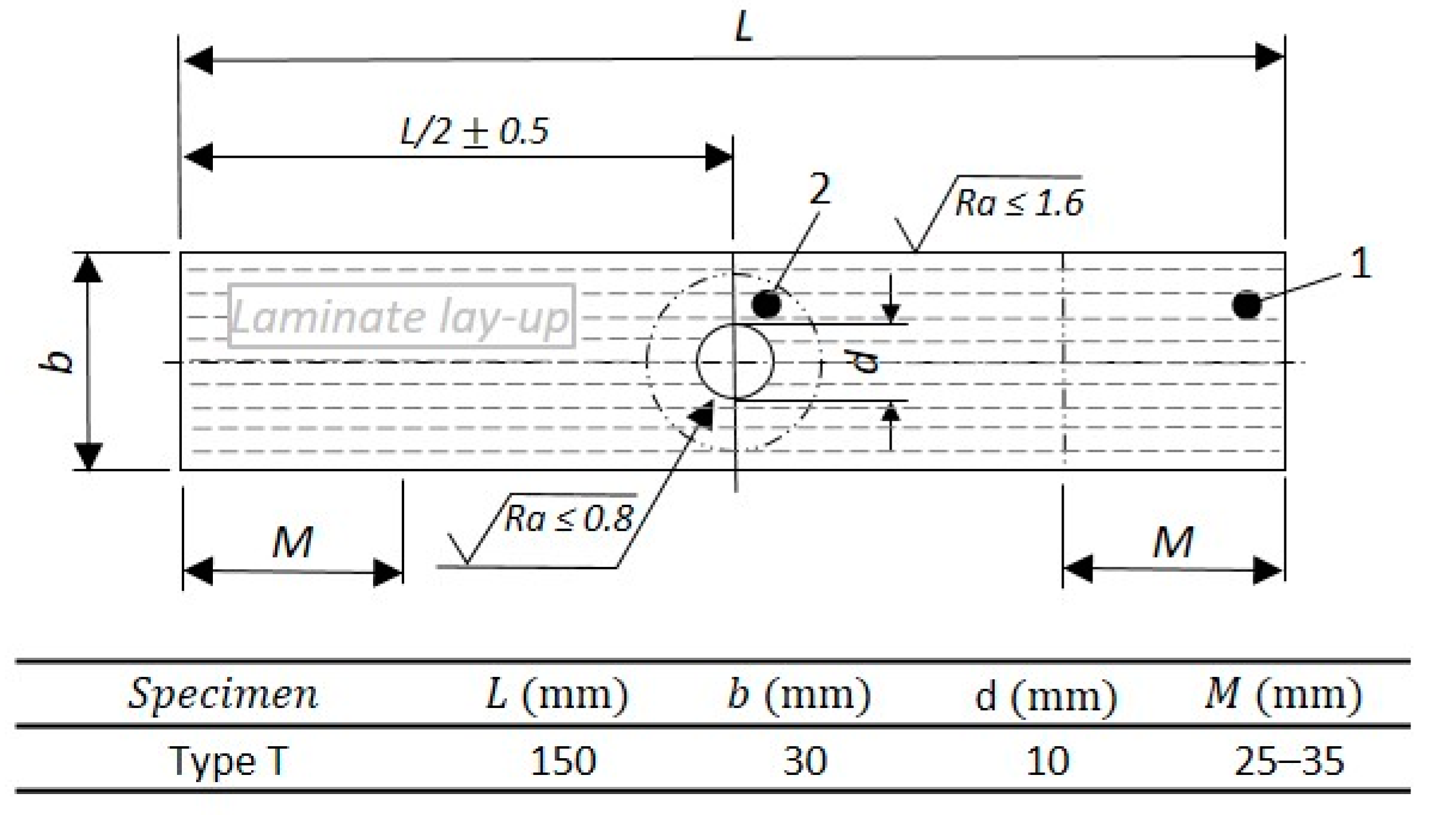
DIN EN 6072 [20] recommends various specimen geometries. This study uses rectangular-sized flat specimens with a centered bolt hole for increased local stress at the notch. DIN EN 6072 provides the measures for the specimen, as shown in Figure 11.
The study includes nine fatigue specimens, three WAAM specimens out of high-strength steel (X90), three WAAM specimens out of ductile steel (SG2) and three SG2/X90-WAAM LMC.
The specimens are tested in tension-tension constant amplitude loading up to failure. The load ratio R is 0.01 and the frequency is 10 Hz. The maximum stress levels are selected in the high-cycle-fatigue range, as shown in Table 7.
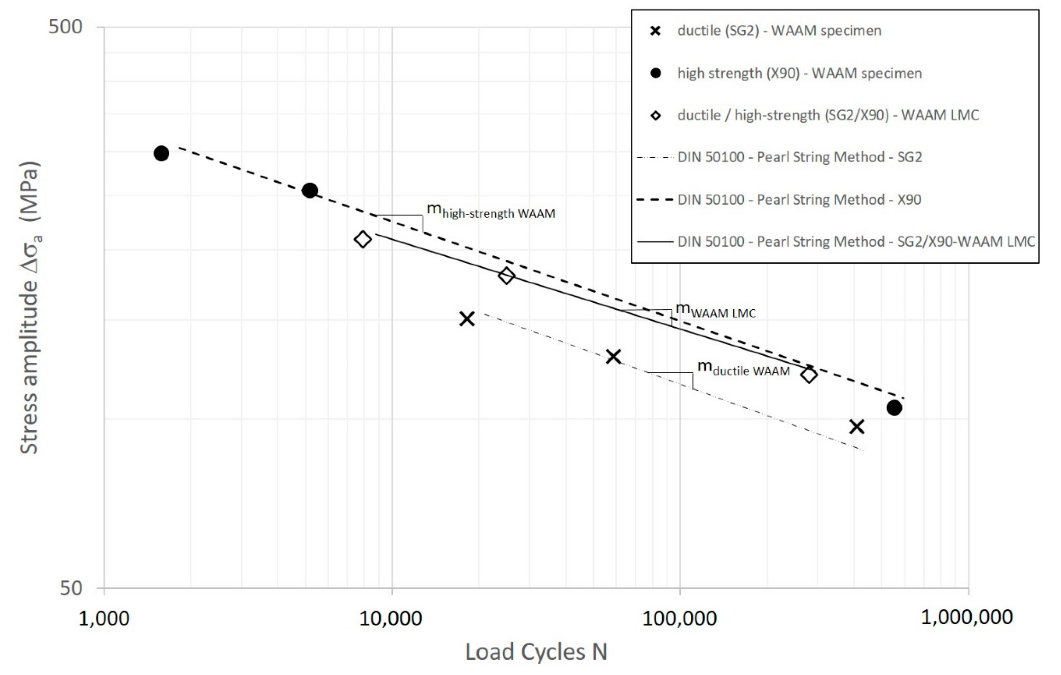
The different stress amplitudes create nine points in the S-N-diagram. The slopes of the S-N-curves of the ductile (SG2) WAAM, the high-strength (X90) WAAM and the SG2/X90-WAAM LMC are determined by using the pearl-string method as recommended in DIN 50100 [21] for a limited number of data points distributed in the HCF range. Figure 12 shows the S-N curves for ductile (SG2), high-strength (X90) WAAM material as well as SG2/X90-WAAM LMC. The S-N curve for the SG2/X90-WAAM LMC approaches the S-N-curve of the high-strength WAAM specimen. The slope of the SG2/X90-WAAM LMC (mWAAM LMC = 3.04) is smaller than the slope of the high-strength (X90) WAAM material (mhigh-strength WAAM = 2.64) and similar to the ductile (SG2) WAAM material (mductile WAAM = 3.08). It is pointed out that these results can only be seen as a first tendency since the number of specimens tested is limited. Currently ongoing further studies will increase the number of data points and enable a statistically stable result. From the fatigue study is concluded that the WAAM LMC seems to have a smaller slope than the S-N-curve of the high-strength steel. No conclusion can be drawn in respect to the level of the endurance limit. The fatigue behavior of WAAM-fabricated LMCs does not follow the rule of mixture, as already found by the Charpy V-notch test.
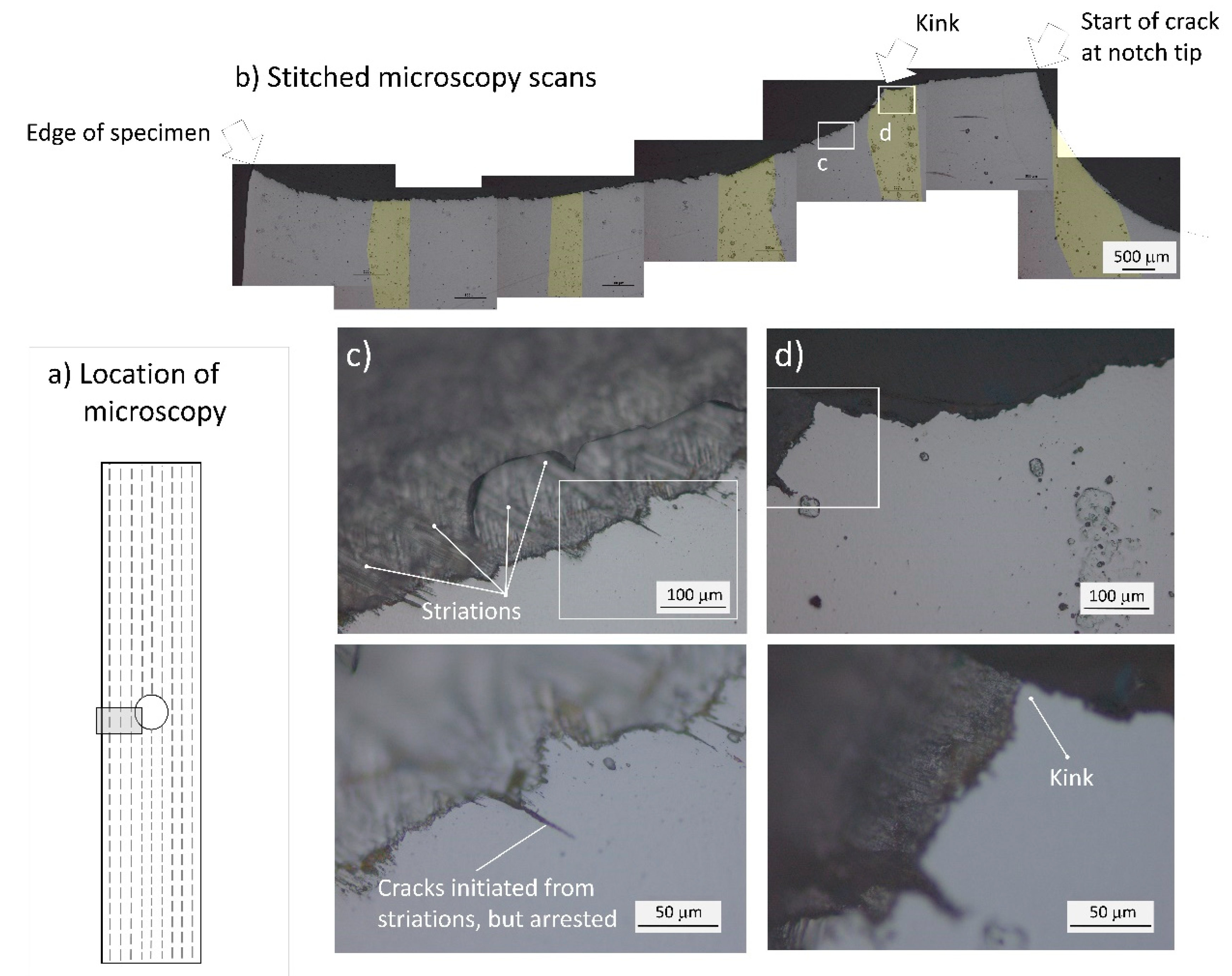
The location for microscopic investigation is selected left of the bolt hole, as annotated in Figure 13a by a black-framed window. It should be mentioned that the notch (bolt hole) tip in all three WAAM LMCs is located in the high-strength steel (X90) material. Figure 13b shows microscopy scans of the fractured SG2/X90-WAAM LMC after fatigue loading. The scans are assembled by stitching.
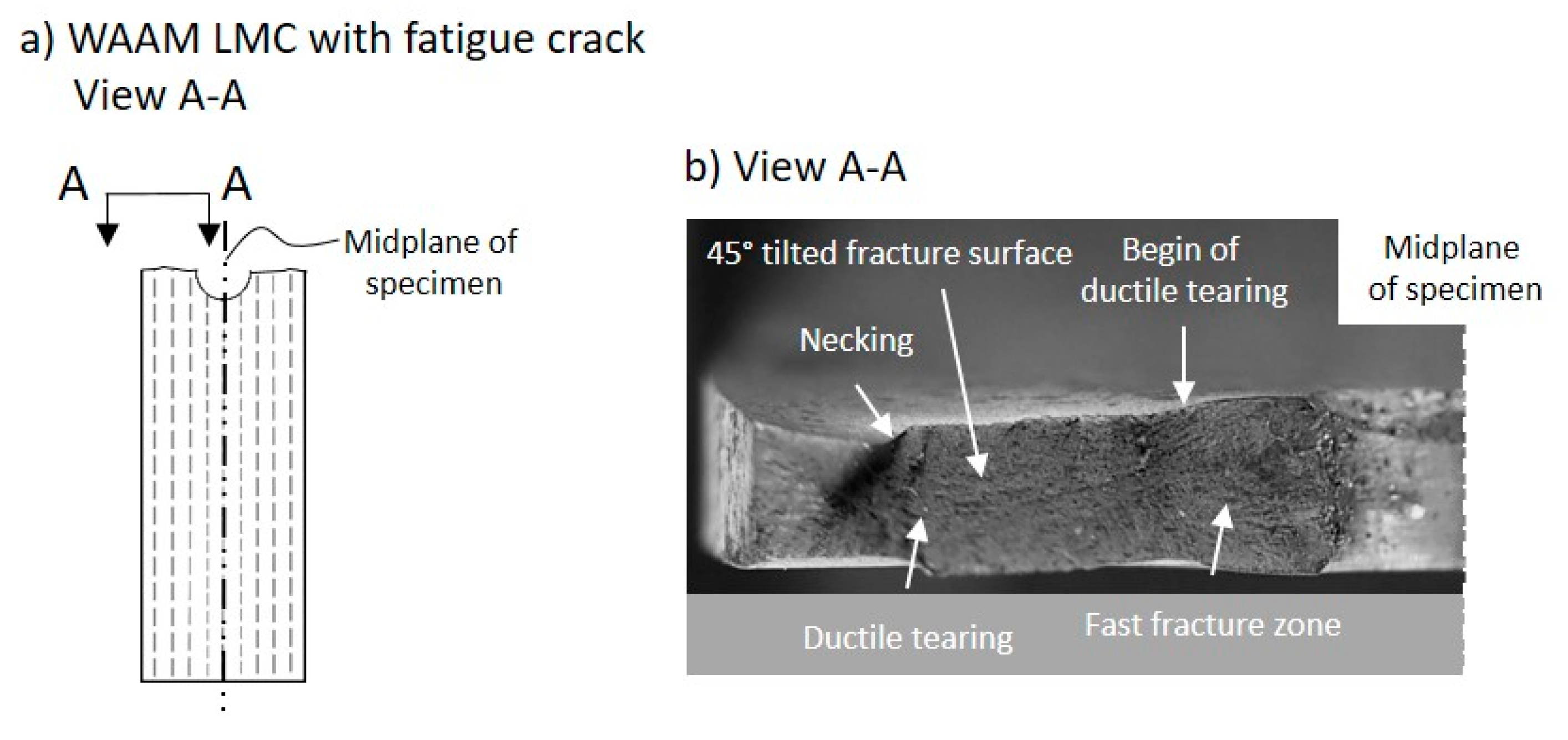
In Figure 13b, the layers of ductile (SG2) WAAM steel are colored. No delamination is recognized along the fracture path, not even at the interfaces from high-strength to ductile WAAM steel layers, as it was found in the Charpy V-notch WAAM LMC specimen. The fatigue specimen is loaded parallel to the WAAM layers, hence not in the crack arrestor orientation as in the Charpy-V-notch test. The crack progresses beginning from the notch tip (see arrow) perpendicular to the loading direction and shows elastic fracture behavior. Within a ductile (SG2) layer, the crack path shows a kink (annotated in Figure 13b) and progresses not perpendicular to the loading direction. From the kink onwards, the crack shows elastic-plastic fracture behavior. This conclusion is confirmed in fracture surface scans, as shown in Figure 14. The fracture surface up to the kink is generated by elastic crack propagation. The fracture surface from the kink onwards is characterized by ductile tearing, an established 45°-tilted surface which proves shear stress activation and essentially necking of the surface, as annotated in Figure 14. Fatigue loading markings (striations) are visible along the fracture surface, as shown in Figure 13c. The striations cause about 50 μm-sized cracks in the section, however these microcracks do not grow further into larger cracks. Apparently, the interface toughness provides a high resistance and delamination does not occur.
5. Conclusions
For the first time, the processing and the performance of laminated metal composites (LMCs) consisting of multiple bilayers of alternating layers of ductile and high-strength steel and processed by wire arc additive manufacturing (WAAM) using a computer code-guided welding robot are investigated. The LMC layup is built up by alternating deposits made of ductile steel (SG2) and high-strength steel (X90) type wires. Governing parameters during processing the LMCs are discussed and parameter settings of this study are provided. The pause time is investigated in dependence of weld bead thickness and number of weld layers. The weld layers within the LMC cross section are sharp but wavy. The mechanical properties of the LMC are strongly influenced by the dilution between the unalloyed SG2 and X90 weld beads causing the hardness of both SG2 and X90 steel to fall in the same range of hardness.
The performance and failure modes of the LMCs are tested under static, impact and high-cycle fatigue loading. Under static tensile loading, yield strength and strain follow the rule of mixture. Accompanying hardness tests are conducted to also assess yield strength and tensile strength from hardness measurements. Under impact loading, where the loading is in the crack arrestor orientation, the WAAM LMC layup resists the crack propagation, particularly at the interfaces between high-strength and mild steel layers. Crack blunting, crack deviation and delamination are recognized. Hence, the dynamic fracture cutting through the LMC is rather stair-stepped. The WAAM laminate shows almost the same fracture energy as the homogenous ductile steel WAAM specimen.
Under high-cycle fatigue loading, the WAAM LMC seems to perform better than the homogenous steel WAAM specimen. Because of the limited number of specimens in this study, this promising result is seen as a first tendency and needs to be confirmed. Microscopy of the laminate section reveals no delamination. The interplay of deformation in the ductile material layers and high-strength layers is seen as part of the fatigue fracture resisting mechanism. Further research is required to clarify this. The results of the Charpy V-notch tests and the fatigue tests of the WAAM LMCs significantly deviate from the rule of mixture and are strongly affected by dilution, as demonstrated with EDX line plots across the LMC layup.
Author Contributions
Conceptualization, M.R. and J.B.; methodology, M.R. and J.B.; software, N.S.; validation, N.S., M.B.; formal analysis, N.S.; investigation, N.S., J.B., M.B., M.R.; resources, M.R.; data curation, N.S.; writing—original draft preparation, M.R.; writing—review and editing, M.R., J.B. and M.B.; visualization, N.S.; supervision, M.R. and J.B.; project administration, J.B.; funding acquisition, M.R. All authors have read and agreed to the published version of the manuscript.
Funding
The support of this research through the Hamburg University of Technology by funding a collaborative welding robot is very much appreciated.
Data Availability Statement
Not applicable.
Acknowledgments
We acknowledge the manufacturing of test samples by Olaf Wittleben at MVB, Dirk Manning and Cord Heineking at FWM, Hamburg University of Technology. The publishing fees supported by the Funding Programme *Open Access Publishing* of Hamburg University of Technology (TUHH) are appreciated.
Conflicts of Interest
The authors declare no conflict of interest.
References
- ISO/ASTM 52900. Standard Terminology for Additive Manufacturing–General Principles–Terminology; International Organization for Standardization (ISO): Geneva, Switzerland, 2015. [Google Scholar]
- Chandrasekaran, S.; Hari, S.; Amirthalingam, M. Wire arc additive manufacturing of functionally graded material for marine risers. Mater. Sci. Eng. A 2020, 792, 139530. [Google Scholar] [CrossRef]
- Rutner, U.D.M. Die Lösung für die Infrastrukturkrise kann nur kreativ sein. Stahlbau 2021, 90, 155–157. [Google Scholar] [CrossRef]
- Kum, D.; Oyama, T.; Wadsworth, J.; Sherby, O. The impact properties of laminated composites containing ultrahigh carbon (UHC) steels. J. Mech. Phys. Solids 1983, 31, 173–186. [Google Scholar] [CrossRef]
- Carreño, F.; Chao, J.; Pozuelo, M.; Ruano, O. Microstructure and fracture properties of an ultrahigh carbon steel–mild steel laminated composite. Scr. Mater. 2003, 48, 1135–1140. [Google Scholar] [CrossRef]
- LeSuer, D.R.; Syn, C.K.; Sherby, O.D.; Wadsworth, J.; Lewandowski, J.J.; Hunt, W.H. Mechanical behaviour of laminated metal composites. Int. Mater. Rev. 1996, 41, 169–197. [Google Scholar] [CrossRef]
- Leedy, K.; Stubbins, J. Copper alloy–stainless steel bonded laminates for fusion reactor applications: Crack growth and fatigue. Mater. Sci. Eng. A 2001, 297, 19–25. [Google Scholar] [CrossRef]
- Koseki, T.; Inoue, J.; Nambu, S. Development of Multilayer Steels for Improved Combinations of High Strength and High Ductility. Mater. Trans. 2014, 55, 227–237. [Google Scholar] [CrossRef] [Green Version]
- Ojima, M.; Inoue, J.; Nambu, S.; Xu, P.; Akita, K.; Suzuki, H.; Koseki, T. Stress partitioning behavior of multilayered steels during tensile deformation measured by in situ neutron diffraction. Scr. Mater. 2012, 66, 139–142. [Google Scholar] [CrossRef]
- Nambu, S.; Michiuchi, M.; Inoue, J.; Koseki, T. Effect of interfacial bonding strength on tensile ductility of multilayered steel composites. Compos. Sci. Technol. 2009, 69, 1936–1941. [Google Scholar] [CrossRef]
- Kümmel, F.; Hausöl, T.; Höppel, H.W.; Göken, M. Enhanced fatigue lives in AA1050A/AA5005 laminated metal composites produced by accumulative roll bonding. Acta Mater. 2016, 120, 150–158. [Google Scholar] [CrossRef]
- Bloyer, D.R.; Ritchie, R.O.; Rao, K.T.V. Fatigue-crack propagation behavior of ductile/brittle laminated composites. Met. Mater. Trans. A 1999, 30, 633–642. [Google Scholar] [CrossRef]
- Wang, F.; Williams, S.; Colegrove, P.; Antonysamy, A.A. Microstructure and Mechanical Properties of Wire and Arc Additive Manufactured Ti-6Al-4V. Met. Mater. Trans. A 2013, 44, 968–977. [Google Scholar] [CrossRef]
- Feucht, T.; Lange, J.; Waldschmitt, B.; Schudlich, A.-K.; Klein, M.; Oechsner, M. Welding Process for the Additive Manufacturing of Cantilevered Components with the WAAM. In Advanced Structured Materials; Springer: Singapore, 2020; pp. 67–78. [Google Scholar]
- Feucht, T.; Lange, J.; Erven, M.; Costanzi, C.B.; Knaack, U.; Waldschmitt, B. Additive manufacturing by means of parametric robot programming. Constr. Robot. 2020, 4, 31–48. [Google Scholar] [CrossRef]
- DIN 50125. Testing of Metallic Materials—Tensile Test Pieces; Beuth Verlag GmbH: Berlin, Germany, 2016; Volume 17. [Google Scholar]
- DIN EN ISO 148-1. Metallic Materials-Charpy Pendulum Impact Test-Part 1: Test Method; Beuth Verlag GmbH: Berlin, Germany, 2017; Volume 40. [Google Scholar]
- Kibria, G.; Jahan, M.P.; Bhattacharyya, B. Micro-Electrical Discharge Machining Processes; Springer: Singapore, 2019. [Google Scholar]
- Hosford, W.F. Mechanical Behavior of Materials; Cambridge University Press (CUP): Cambridge, UK, 2010. [Google Scholar]
- Din, E. 6072, Aerospace series-Metallic materials-Test methods-Constant amplitude fatigue testing. Ger. Inst. Stand. Berl. Ger. 2011, 1, 68. [Google Scholar]
- DIN 50100. Load Controlled Fatigue Testing–Execution and Evaluation of Cyclic Tests at Constant Load Amplitudes on Metallic Specimens and Components; Beuth Verlag GmbH: Berlin, Germany, 2016; Volume 111. [Google Scholar]
Figure 1.
(a) Collaborative robot (Universal Robot UR10e) guiding the welding equipment (Lorch S5 Speedpuls XT); (b) WAAM LMC.
Figure 1.
(a) Collaborative robot (Universal Robot UR10e) guiding the welding equipment (Lorch S5 Speedpuls XT); (b) WAAM LMC.

Figure 2.
(a) WAAM LMC cross section—as manufactured and cut and polished for fatigue testing; (b) relation of weld bead thickness, pause time and number of layers.
Figure 2.
(a) WAAM LMC cross section—as manufactured and cut and polished for fatigue testing; (b) relation of weld bead thickness, pause time and number of layers.

Figure 3.
Vickers hardness HV3 and HV10 measurement at equidistant measurement positions in the middle of a weld layer.
Figure 3.
Vickers hardness HV3 and HV10 measurement at equidistant measurement positions in the middle of a weld layer.

Figure 4.
EDX-spectrum analysis (a) SEM scan; (b) line plot for Cr and Ni; (c) EDX spectrum analysis; (d) table listing Cr- and Ni-measurements in spectra 1 and 2, respectively.
Figure 4.
EDX-spectrum analysis (a) SEM scan; (b) line plot for Cr and Ni; (c) EDX spectrum analysis; (d) table listing Cr- and Ni-measurements in spectra 1 and 2, respectively.

Figure 5.
(a) WAAM-fabricated LMC tensile specimen; (b) static tension specimen geometry according to DIN 50125; (c) position of cut-out.
Figure 5.
(a) WAAM-fabricated LMC tensile specimen; (b) static tension specimen geometry according to DIN 50125; (c) position of cut-out.

Figure 6.
Static tension WAAM specimen out of ductile steel (SG2), high-strength steel (X90) and SG2/X90-WAAM LMC after static tension testing.
Figure 6.
Static tension WAAM specimen out of ductile steel (SG2), high-strength steel (X90) and SG2/X90-WAAM LMC after static tension testing.

Figure 7.
Static tension test; stress–strain curves for all three specimen, homogenous ductile (SG2) WAAM, homogenous high-strength (X90) WAAM and SG2/X90-WAAM LMC.
Figure 7.
Static tension test; stress–strain curves for all three specimen, homogenous ductile (SG2) WAAM, homogenous high-strength (X90) WAAM and SG2/X90-WAAM LMC.

Figure 8.
(a) WAAM LMC sample as manufactured; (b) EDM-cutting the top; (c) Charpy V-notch specimen with its final geometry (H/B/L = 10/10/55 mm) (V-notch annotated).
Figure 8.
(a) WAAM LMC sample as manufactured; (b) EDM-cutting the top; (c) Charpy V-notch specimen with its final geometry (H/B/L = 10/10/55 mm) (V-notch annotated).

Figure 9.
Charpy V-notch test (a) WAAM LMC Charpy V-notch specimen cross section; (b) Charpy V-notch specimen after testing.
Figure 9.
Charpy V-notch test (a) WAAM LMC Charpy V-notch specimen cross section; (b) Charpy V-notch specimen after testing.

Figure 10.
Schematic sketch of area a and area b; area a: crack blunting and diversion, no remaining delamination and crack nucleation at interface between the high-strength and ductile material layers; area b: remaining delamination at interface between high-strength and ductile material layers.
Figure 10.
Schematic sketch of area a and area b; area a: crack blunting and diversion, no remaining delamination and crack nucleation at interface between the high-strength and ductile material layers; area b: remaining delamination at interface between high-strength and ductile material layers.

Figure 11.
Fatigue WAAM LMC specimen according to DIN EN 6072 adapted from [20].
Figure 11.
Fatigue WAAM LMC specimen according to DIN EN 6072 adapted from [20].

Figure 12.
S-N-curves for ductile (SG2) WAAM, high-strength (X90) WAAM and SG2/X90-WAAM LMC; trend lines assessed by pearl-string method (DIN 50100:2016-12) [21].
Figure 12.
S-N-curves for ductile (SG2) WAAM, high-strength (X90) WAAM and SG2/X90-WAAM LMC; trend lines assessed by pearl-string method (DIN 50100:2016-12) [21].

Figure 13.
Fatigue fracture of WAAM LMC specimen; (a) location of microscopy; (b) microscopy scans of crack path; (c) striations on fracture surface; (d) kink.
Figure 13.
Fatigue fracture of WAAM LMC specimen; (a) location of microscopy; (b) microscopy scans of crack path; (c) striations on fracture surface; (d) kink.

Figure 14.
Fracture surface of fatigue-tested WAAM LMC. (a) WAAM LMC with fatigue crack View A-A; (b) View A-A.
Figure 14.
Fracture surface of fatigue-tested WAAM LMC. (a) WAAM LMC with fatigue crack View A-A; (b) View A-A.


Table 1.
Designation and chemical compositions of filler wires.
| Name | Designation | C (%) | Si (%) | Mn (%) | Ni (%) | Mo (%) | Cr (%) |
|---|---|---|---|---|---|---|---|
| X90 | EN ISO 16834-A: G89 4 M21 Mn4Ni2CrMo | 0.1 | 0.7 | 1.7 | 2.0 | 0.5 | 0.3 |
| SG2 | EN ISO 14341: G42 4 M G3Si1 | 0.1 | 0.85 | 1.45 | 0 | 0 | 0 |
Table 2.
Parameters for WAAM-fabricated LMCs.
| Specimen | Electric Current (A) | Wire Feed Speed (mm/s) | Welding Speed (mm/s) | Pause Time (s) | Heat Input (J/mm) | CTWD (mm) | Weld Bead Thickness (mm) |
|---|---|---|---|---|---|---|---|
| WAAM LMC | 150 | 7.2 | 10 | 60 | 270 | 13 | 1.3 |
| X90-WAAM | 150 | 7.2 | 10 | 60 | 270 | 12 | 1.3 |
| SG2-WAAM | 150 | 7.2 | 10 | 60 | 270 | 13 | 1.3 |
CTWD: contact-tip-to-work-distance.
Table 3.
Measured Vickers hardness of SG2/X90-WAAM LMC.
| HV3 Measurements | SG2-Ductile Steel Layer | X90-High Strength Steel Layer | ||
|---|---|---|---|---|
| Position | Layer 1 | Layer 2 | Layer 1 | Layer 2 |
| 0 mm | 178 | 161 | 202 | 182 |
| 2.5 mm | 190 | 174 | 182 | 174 |
| 5 mm | 193 | 182 | 202 | 190 |
| Mean value | 187.0 | 172.3 | 195.3 | 182.0 |
| Standard deviation | 7.9 | 10.6 | 11.5 | 8.0 |
Table 4.
Measured Vickers hardness HV of SG2/X90-WAAM LMC with equal spacing between measurement positions.
Table 4.
Measured Vickers hardness HV of SG2/X90-WAAM LMC with equal spacing between measurement positions.
| Parameter | SG2-Ductile Steel Layer | X90-High-Strength Steel Layer | ||
|---|---|---|---|---|
| Layer 1 | Layer 2 | Layer 1 | Layer 2 | |
| Mean Vickers hardness (HV3) | 187.0 | 172.3 | 195.3 | 182.0 |
| Mean yield strength (MPa) | 392.4 | 344.1 | 419.6 | 376.0 |
| Mean ultimate strength (MPa) | 609.1 | 560.6 | 636.5 | 592.6 |
Table 5.
Yield strength, tensile strength, fracture strain and impact energy values of the steels applied; manufacturer information.
Table 5.
Yield strength, tensile strength, fracture strain and impact energy values of the steels applied; manufacturer information.
| Product Name | Yield Strength Manufacturer Info/Measured (MPa) | Tensile Strength (MPa) | Fracture Strain (%) | Charpy V-Notch Energy at 20 °C (J) |
|---|---|---|---|---|
| Böhler EMK (SG2) | Manufacturer info: 440 | 560 | 30 | 160 |
| Measured (Offset yield point ReH): 330 | 440 | |||
| DRATEC DT-X90 | Manufacturer info: 880-920 | 940–980 | 16–20 | 65–95 |
| Measured (Offset Yield Rp0.2): 475 | 870 |
Table 6.
Charpy V-notch energy values of WAAM-specimen out of ductile steel (SG2), high-strength steel (X90) and SG2/X90-WAAM LMC.
Table 6.
Charpy V-notch energy values of WAAM-specimen out of ductile steel (SG2), high-strength steel (X90) and SG2/X90-WAAM LMC.
| Sample | SG2-Ductile WAAM (J) | X90-High-Strength WAAM (J) | SG2/X90-WAAM LMC (J) |
|---|---|---|---|
| 1 | 149 | 66 | 121 |
| 2 | 170 | 62 | 156 |
| 3 | 169 | 62 | 156 |
| 4 | 158 | 67 | |
| 5 | 156 | 60 | |
| 6 | 122 | 55 | |
| Mean value | 154 | 62 | 144 |
| Standard deviation | 17.60 | 4.33 | 20.21 |
Table 7.
Maximum stress levels in high-cycle-fatigue (HCF) range of high-strength (X90) WAAM, ductile (SG2) WAAM and SG2/X90-WAAM LMC specimen.
Table 7.
Maximum stress levels in high-cycle-fatigue (HCF) range of high-strength (X90) WAAM, ductile (SG2) WAAM and SG2/X90-WAAM LMC specimen.
| Specimen | HCF Stress Level 1 (MPa) | HCF Stress Level 2 (MPa) | HCF Stress Level 3 (MPa) |
|---|---|---|---|
| High-strength (X90) WAAM | 0.7 fu = 609 | 0.6 fu = 522 | 0.25 fu = 218 |
| Ductile (SG2) WAAM | 0.7 fu = 308 | 0.6 fu = 264 | 0.4 fu = 176 |
| SG2/X90-WAAM LMC | 0.7 fu = 427 | 0.6 fu = 366 | 0.4 fu = 244 |
fu: ultimate tensile strength.
Publisher’s Note: MDPI stays neutral with regard to jurisdictional claims in published maps and institutional affiliations. |
© 2021 by the authors. Licensee MDPI, Basel, Switzerland. This article is an open access article distributed under the terms and conditions of the Creative Commons Attribution (CC BY) license (https://creativecommons.org/licenses/by/4.0/).
Share and Cite
MDPI and ACS Style
Spalek, N.; Brunow, J.; Braun, M.; Rutner, M. WAAM-Fabricated Laminated Metal Composites. Metals 2021, 11, 1948. https://doi.org/10.3390/met11121948
AMA Style
Spalek N, Brunow J, Braun M, Rutner M. WAAM-Fabricated Laminated Metal Composites. Metals. 2021; 11(12):1948. https://doi.org/10.3390/met11121948
Chicago/Turabian StyleSpalek, Niclas, Jakob Brunow, Moritz Braun, and Marcus Rutner. 2021. "WAAM-Fabricated Laminated Metal Composites" Metals 11, no. 12: 1948. https://doi.org/10.3390/met11121948
Note that from the first issue of 2016, this journal uses article numbers instead of page numbers. See further details here.