
Abstract
Polycrystalline and epitaxial thin films composed of a single phase of yttrium iron garnet (YIG) have been synthesized on silica glass and single-crystalline gadolinium gallium garnet substrates, respectively, by the mist chemical vapor deposition (CVD) method. The element Y can be found in the deposited thin films only when an aprotic polar solvent such as acetone is employed for the preparation of the precursor solutions. The crystal structure, magnetic properties, and magneto-optical properties of the thin films are explored. The maximum Faraday rotation angle observed in the present epitaxial YIG thin film is 3.66°/µm at 441 nm, as far as we know, which is higher than those reported for YIG films prepared by other methods, suggesting that the mist CVD method is effective for obtaining epitaxial thin films of multiple oxides.
Export citation and abstract BibTeX RIS
1. Introduction
Yttrium iron garnet (YIG), a prototype of garnet-type ferrite, with the chemical formula of Y3Fe5O12 has been widely used as magneto-optical devices based on the Faraday effect. The compound also had a period of great prosperity in the 1970s for bubble memories. Moreover, YIG was also used in microwave applications due to its extremely low magnetic loss.1) In recent years YIG has attracted considerable attention because the combination of the spin Hall effect in Pt and the generation of spin waves in YIG may be applicable to novel information transfer devices with minimal spin-wave damping.2,3)
As for the preparation method of YIG thin films, liquid phase epitaxy (LPE) has been most widely used for synthesizing epitaxial films, and over the past decades, this has almost been the only method for epitaxial growth of high-quality YIG films.4) Recently, in association with the significant progress in thin-film deposition techniques, various methods have been utilized for the preparation of YIG thin films such as sol–gel, spray pyrolysis, radio-frequency sputtering, and chemical vapor deposition (CVD).5–8) Very recently, a pulsed laser deposition (PLD) technique has emerged as a mainstream synthesis method for YIG thin films with high quality comparable to those prepared by LPE.9) The thin-film process is very important for the application of YIG-based compounds as Faraday effect devices. Also, the technique enables us to fabricate metastable phases such as Bi3Fe5O12,10) as well as YIG with Y replaced by a large amount of Bi or other rare-earth elements such as Ce and Pr,11–13) whose Faraday rotation angles are much larger than that of YIG.
In the present study, we have synthesized YIG thin films by the mist CVD method, an emerging method known as a potential candidate for low-cost, large-area, and industrial-scale processes. Indeed, the mist CVD method is simple and inexpensive; so long as reagents can be dissolved in solvents and the solution can be ultrasonically atomized, thin films are grown efficiently and homogeneously at atmospheric pressure.14,15) The mist CVD method has established itself as one of the most versatile methods for the preparation of thin films. Until today, thin films of numerous oxide semiconductors and conductive polymers have been successfully deposited by this method,16–19) and thirty elements at least are known to be used for the mist CVD method. More importantly, the mist CVD method possesses both the merits of solution process and vapor deposition process; the precursor is homogeneous on the atomic scale, and deposition rate and growth temperature can be precisely controlled. In this paper, we report on the successful synthesis of polycrystalline and epitaxial thin films composed of a single phase of YIG and demonstrate that the resultant YIG thin films show a large Faraday effect.
2. Experimental procedure
The mist CVD setup utilized in this study is a fine-channel type mist sourced film former (TOUKI MSFF-FC). Polycrystalline YIG thin films were grown on silica glass substrates by changing preparation conditions, so that we could optimize the preparation conditions for a single phase of YIG. Epitaxially grown YIG thin films were also prepared on (111)-oriented gadolinium gallium garnet (GGG) substrates. The precursor solution was prepared by dissolving tris(acetylacetonato)iron(III), Fe(C5H8O3)3, and tris(acetylacetonato)yttrium(III) hydrate, Y(C5H8O3)3 nH2O, in acetone (the value of n was determined by thermogravimetry). The choice of acetone as a solvent is based on the following fact. It was observed that the element Y could be hardly found in deposited thin films when aqueous solution was used in the mist CVD process. Various kinds of solvents were tested for the preparation of YIG thin films; and consequently, aprotic polar solvents were found to be feasible, although the reason is not clear at this moment. Considering toxicity and mist generation rate, acetone was chosen as an appropriate solvent.
To optimize the process conditions, solutions having various molar ratios of Y(C5H8O3)3/Fe(C5H8O3)3 were used. Hereafter, we refer to the molar ratio of the starting materials as [Y]/[Fe]. Because of the large difference in deposition rate between yttrium oxide and iron oxide, an excess amount of the precursor of Y was used, so that the [Y]/[Fe] ratio larger than the Y/Fe ratio of chemical formula, i.e., 0.600, was required for the preparation of YIG thin films. The total concentration of Y and Fe in the solutions, [Y] + [Fe], was maintained at 0.050 mol/L. The precursor solution was ultrasonically atomized using a 2.4 MHz transducer, and the mist particles were transferred to the reaction area with nitrogen (N2) carrier gas at a flow rate of 3 L/min. The substrate temperature was mainly maintained at 500 °C and the reaction time was set at 20 min. The mist particles were supplied at a rate of 1.0 mL/min. Because as-deposited thin films were amorphous, post annealing was carried out at 800 °C for 60 min.
The crystal structure of thin films was analyzed by X-ray diffraction (XRD). The composition of the thin films was determined by Rutherford backscattering spectrometry (RBS). Film thickness was evaluated from the cross-sectional images obtained by field emission scanning electron microscopy (FE-SEM). Magnetic properties were measured using a superconducting quantum interference device magnetometer (SQUID). Faraday rotation angle was evaluated using a polarization modulation technique with a Xe lamp as a light source. The sample was placed in a static magnetic field of 15 kOe, and rotation angle was measured in a wavelength range from 350 to 850 nm at room temperature.
3. Results and discussion
Diffraction lines are not observed in the XRD patterns of as-deposited thin films grown below 500 °C (not shown), indicating that the as-deposited thin films are amorphous. Hence, post annealing is needed for the crystallization of YIG. To avoid crystallization of yttrium silicate by the reaction of thin films with silica glass substrates, the post annealing was carried out at 800 °C. Figure 1 shows the XRD patterns of thin films prepared from precursors with different [Y]/[Fe] ratios. When the ratio is equal to 0.600, the diffraction lines in the XRD pattern are assigned to hematite, α-Fe2O3, with a small amount of orthorhombic yttrium orthoferrite, which is the high-temperature phase of YFeO3. With an increase in the ratio up to 1.000, the orthorhombic YFeO3 becomes the dominant phase. YIG and hexagonal YFeO3 phases appear when the [Y]/[Fe] ratio is larger than 1.333; a broad diffraction line at 2θ of 30.4°, observed in the thin films prepared from the precursors whose [Y]/[Fe] ratios are equal to 1.333, 1.400, 1.450, and 1.483, corresponds to the 101 plane of hexagonal YFeO3, i.e., the low-temperature phase of YFeO3. Hexagonal YFeO3 solid solutions with a wide range of Y/Fe ratios are known to be formed at low temperatures.20) For the thin films prepared from precursor solutions with larger [Y]/[Fe] ratios such as 1.545, 1.636, and 1.667, broad diffraction lines observed at approximately 2θ = 29.4, 30.4, and 33.2° are presumably attributable to the solid solutions based on hexagonal YFeO3. In particular, when the [Y]/[Fe] ratio is equal to 1.667, all the diffraction lines match those of hexagonal YFeO3. The YIG phase is observed as the main product for the range of 1.333–1.545; in particular, when the [Y]/[Fe] ratio of the precursor solution is equal to 1.500, the single phase of YIG without any impurity phases can be obtained. Thus, the results of XRD analysis can be summarized as follows. When the [Y]/[Fe] ratio is low, α-Fe2O3 and orthorhombic YFeO3 are precipitated, and when the [Y]/[Fe] ratio is high, the hexagonal YFeO3 solid solutions are formed. For the middle [Y]/[Fe] ratio, YIG is obtained as the main phase.

Fig. 1. XRD patterns of thin films grown on silica glass substrates using various [Y]/[Fe] ratios. The [Y]/[Fe] ratio denotes the molar ratio of Y to Fe in the starting solutions.
Download figure:
Standard image High-resolution imageThe average grain size of YIG thin films is calculated by the Williamson–Hall method:
where β, λ, ξ, and d indicate the full width at half maximum (FWHM), the wavelength of X-ray (1.54060 Å), the strain, and the grain size, respectively. The relationship between β cos θ/λ and sin θ/λ is shown in Fig. 2(a). By the linear least-squares method, the strain and grain size are estimated from the slope and the intercept. The average grain size of the polycrystalline YIG thin film prepared in the present study is 91.5 nm. The result of RBS for the YIG thin film grown on the silica glass substrate is shown in Fig. 2(b). From the analysis of signals from the constituent atoms Y, Fe, O, and Si, it is found that the distribution of elements is homogeneous in depth, and the chemical composition of the thin film is determined as  , which exactly agrees with the stoichiometric composition. The compositions of the thin films deposited under different conditions are listed in Table I, where the Y to Fe molar ratios of the thin films determined by RBS measurements are summarized. As mentioned above, Y is hardly found in the thin films prepared from aqueous solutions even at growth temperatures up to 700 °C. The molar ratios of Y to Fe are plotted in Fig. 3 as a function of [Y]/[Fe] of precursors dissolved in acetone. A linear relationship is observed, indicating that the composition of thin films can be controlled by the [Y]/[Fe] ratio of precursors. Growth temperature is another important parameter for the film deposition. Figure 4 shows the molar ratios of Y to Fe in the thin films as a function of growth temperature. As growth temperature increases, an increase in molar ratios of Y to Fe is observed in both series of [Y]/[Fe] equal to 1.500 and 1.667, indicating that the activation energy for deposition is higher for yttrium oxide than for iron oxide. A SEM image of the polycrystalline YIG thin film grown on the silica glass substrate is shown in Fig. 5(a). A smooth and featureless surface can be observed. The thickness of the thin film is estimated to be 155.4 nm. For the thin film prepared from the precursors whose [Y]/[Fe] is equal to 1.513, aggregation of YFeO3 nanoparticles can be clearly observed, as shown in Fig. 5(b).

Download figure:
Standard image High-resolution image
Fig. 2. Williamson–Hall plot (a) and RBS signals (b) of single-phase YIG thin film deposited on silica glass substrate.
Download figure:
Standard image High-resolution image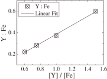
Fig. 3. Molar ratio of Y to Fe in the thin films as a function of [Y]/[Fe].
Download figure:
Standard image High-resolution image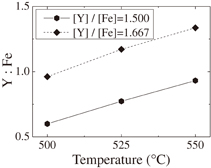
Fig. 4. Molar ratio of Y to Fe in the thin films as a function of growth temperature.
Download figure:
Standard image High-resolution image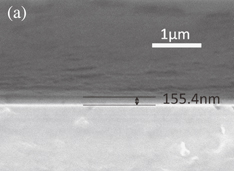
Download figure:
Standard image High-resolution image
Fig. 5. SEM images of polycrystalline YIG thin film prepared from precursor whose [Y]/[Fe] ratio is 1.500 (a) and thin film prepared from precursor whose [Y]/[Fe] ratio is equal to 1.513 (b).
Download figure:
Standard image High-resolution imageTable I. Composition of the thin films deposited under different conditions.
| [Y]/[Fe] (Y(C5H8O3)3/Fe(C5H8O3)3) | Solvent | Growth temperature (°C) | Molar ratio of Y to Fe in thin film (determined by RBS) |
|---|---|---|---|
 |
Water | 500 | 0 |
 |
Water | 700 | 0 |
 |
Acetone | 500 | 0.221 |
 |
Acetone | 500 | 0.283 |
 |
Acetone | 500 | 0.383 |
 |
Acetone | 500 | 0.600 |
Room temperature magnetization as a function of external magnetic field is shown in Fig. 6. A hysteresis loop is clearly observed, indicating that the present YIG thin film exhibits ferrimagnetic behavior at room temperature, as naturally expected from the fact that the Curie temperature reported for YIG is 550 K.21) The magnetization saturates at about 0.05 T and reaches about 125 emu/cm3 close to that of a single-crystalline YIG film grown by the LPE method, i.e., 140 emu/cm3.22) The saturation magnetization of the present polycrystalline thin film is higher than other epitaxially grown YIG thin films; for example, the magnetization of the YIG thin film grown on the GGG substrate by radio frequency sputtering is approximately 96 emu/cm3.23) The magnetization of YIG at room temperature is caused by the superexchange interaction among Fe3+ ions at the octahedral (16a) and tetrahedral (24d) sites, which are coupled antiferromagnetically. Hence, Fe2+ ions, if present and homogeneously distributed at both octahedral and tetrahedral sites, would lead to a reduction of magnetization because the magnetic moment is larger for Fe3+ than for Fe2+ ions. Thus, the high saturation magnetization is achieved in the mist CVD-derived thin film probably because the preparation in air suppresses the formation of oxygen vacancies, and as a result, all the Fe ions are expected to be present in the trivalent state.
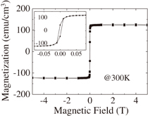
Fig. 6. Room temperature magnetization as a function of magnetic field for polycrystalline YIG thin film deposited on silica glass substrate. The inset shows an enlarged view in the low field range.
Download figure:
Standard image High-resolution imageThe wavelength dependence of Faraday rotation angle is illustrated in Fig. 7 which is in accord with the fact that spectrum of wavelength dependence of Faraday rotation of YIG manifests maxima at 2.53 (490 nm) and 2.81 eV (441 nm) as reported previously.24) The maximum Faraday rotation angle, i.e., θF = 3.02°/µm at 440 nm, observed for the present YIG thin film is close to that of the epitaxial YIG film prepared by LPE.25)

Fig. 7. Wavelength dependence of Faraday rotation angle for polycrystalline YIG thin film deposited on silica glass substrate.
Download figure:
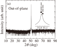
Standard image High-resolution imageWe also prepared a YIG thin film on the (111)-oriented GGG substrate. The concentration of precursor solution and other experimental conditions followed those for the single-phase YIG thin film prepared on the silica glass substrate, i.e., the [Y]/[Fe] ratio of precursor solution was equal to 1.500 and the growth temperature and post annealing temperature were 500 and 800 °C, respectively. The out-of-plane XRD pattern is shown in Fig. 8(a). Only the 444 line of YIG appears in the out-of-plane XRD pattern, indicating that no impurity phases are precipitated. Figure 8(b) depicts the XRD pattern obtained by in-plane measurement, in which only 211 and 422 diffraction lines are observed due to the in-plane orientations. The results of XRD measurements indicate that the present YIG thin film is epitaxially grown on the GGG substrate. The wavelength dependence of Faraday rotation for this epitaxial thin film is shown in Fig. 9. The maximum Faraday rotation angle θF reaches 3.66°/µm at 441 nm. As far as we know, this is the highest Faraday rotation angle among those reported for YIG thin films measured at room temperature. Because the Faraday effect of YIG is mainly caused by the charge-transfer transitions in octahedral FeO6 and tetrahedral FeO4 complexes, the angles of Faraday rotation are proportional to the magnetizations of 16a- and 24d-iron sublattices and to the external magnetic field.26) Therefore, the high magnetization obtained for the present epitaxial as well as polycrystalline YIG thin films presumably leads to the large Faraday rotation angles of the thin films.
Download figure:
Standard image High-resolution image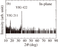
Fig. 8. Out-of-plane (a) and in-plane (b) XRD patterns of YIG thin film grown on GGG substrate.
Download figure:
Standard image High-resolution image
Fig. 9. Wavelength dependence of Faraday rotation angle for epitaxial YIG thin film deposited on GGG substrate.
Download figure:
Standard image High-resolution image
4. Conclusions
YIG thin films can be synthesized by the mist CVD method when an aprotic polar solvent is employed in the precursor solution. The saturation magnetization and maximum Faraday rotation angle are 125 emu/cm3 and 3.02°/µm, respectively, for the polycrystalline thin film composed of a single phase of YIG grown on the silica glass substrate. The epitaxial YIG thin film grown on the (111)-oriented GGG substrate has a high Faraday rotation angle, i.e., θF = 3.66°/µm at 441 nm. We believe that the mist CVD method is effective for obtaining multiple oxide thin films and also for achieving high quality epitaxial thin films.
Acknowledgement
This research was supported by a Grant-in-Aid for Scientific Research (A) (No. 25249090) of the Ministry of Education, Culture, Sports, Science and Technology (MEXT).