Long-term intravital imaging of the multicolor-coded tumor microenvironment during combination immunotherapy
- Wuhan National Laboratory for Optoelectronics-Huazhong University of Science and Technology, China
- Huazhong University of Science and Technology, China
Figures
Figure 1 with 3 supplements
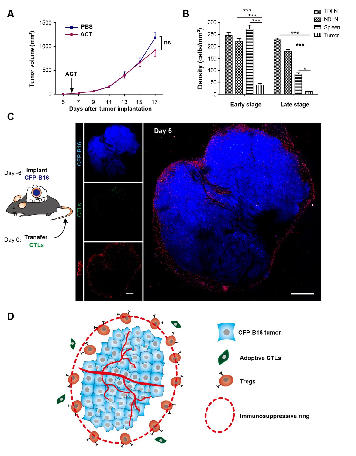
‘Immunosuppressive ring’ formed by Tregs in CFP-B16 tumor-bearing mice, which inhibited the anti-tumor efficacy of the adoptive CTLs.
(A) Tumor growth curves for CFP-B16 tumors of mice treated with ACT or PBS control. The data are represented as the mean ± SEM tumor volume (n = 12–14, three independent experiments). ns: not significant, (Figure 1—source data 1). (B) Density of carboxyfluorescein succinimidyl ester (CFSE)-labeled CTLs within different organs (tumor-draining lymph nodes (TDLNs), non-tumor-draining lymph nodes (NDLNs), spleens, and tumors). The density was determined by counting the number of CFSE-labeled CTLs per mm2 on frozen tissue sections. The data are represented as the mean ± SEM (n = 18–22 fields, 0.18 mm2 per field) from three independent experiments. *p<0.05, **p<0.01, ***p<0.001, (Figure 1—source data 2). (C) Large-field intravital images of an ‘immunosuppressive ring’ around the CFP-B16 tumor. Blue – CFP-B16 tumor; red – Tregs (Foxp3-mRFP cells); green – CFSE-labeled CTLs. The left panel shows different single color channels of the tumor microenvironment, and the right panel shows the three color channels merged. Scale bar: 500 µm. (D) Schematic diagram of the ‘immunosuppressive ring’ in the tumor microenvironment.
-
Figure 1—source data 1
Tumor growth curves for CFP-B16 tumors of mice treated with ACT or PBS.
- https://doi.org/10.7554/eLife.14756.004
-
Figure 1—source data 2
Density of CFSE-labeled CTLs within different organs.
- https://doi.org/10.7554/eLife.14756.005
Figure 1—figure supplement 1

Establishment and characterization of CFP-B16 tumor-specific CTLs.
(A) CFSE- and propidium iodine (PI)-based assays to assess the cytotoxicity of CTLs added to the CFP-B16 tumor cells or added to the splenocytes by flow cytometry, and the control group which was composed of splenocytes added to the CFP-B16 tumor cells. The data are represented as the mean ± SD from three independent experiments. (B) Analysis and characterization of the in vitro-activated CTLs. The data are representative of similar results from three independent experiments.
Figure 1—figure supplement 2
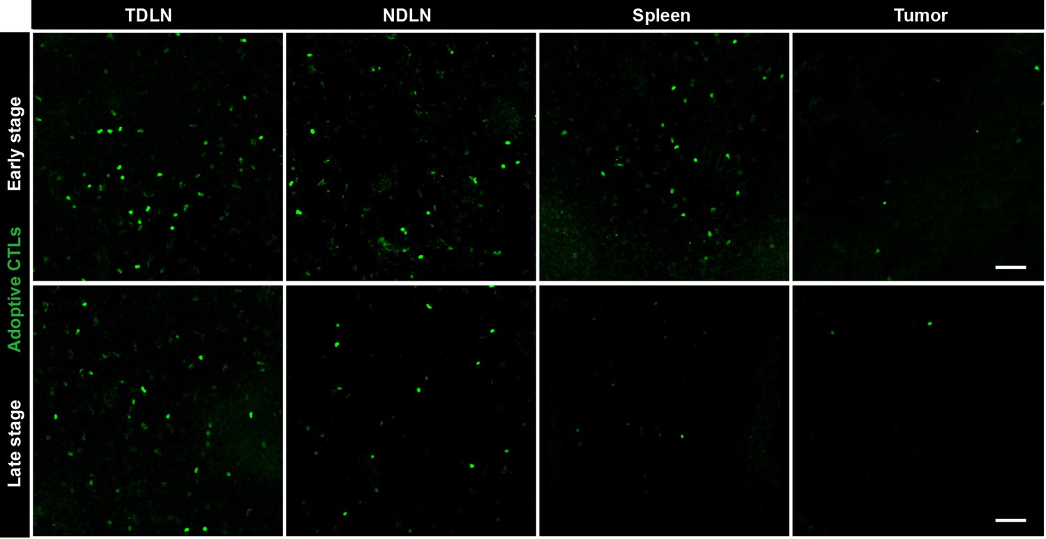
Fluorescence microscopy images showing the distribution of CFSE-labeled CTLs in different organs.
Representative sections of tumor-draining lymph node (TDLN), non-tumor-draining lymph node (NDLN), spleen and tumor tissues were collected from tumor-bearing mice on Days 1–3 (early stage) and Days 4–6 (late stage) after the adoptive transfer of CTLs. The top row represents the early stage, and the bottom row represents the late stage. CFSE-labeled adoptively transferred CTLs are shown in green. Scale bars: 50 µm.
Figure 1—figure supplement 3
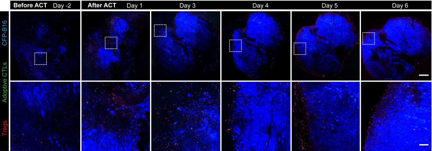
Long-term and large-field imaging of the process by which Tregs formed an immunosuppressive ring.
CFP-B16 tumor is shown in blue (CFP), Tregs are shown in red (mRFP), and adoptively transferred CTLs are shown in green (CFSE, rarely observed). Top row: large-field images; scale bar: 500 µm. Bottom row: images of the region of interest; scale bar: 100 µm.
Figure 2 with 2 supplements
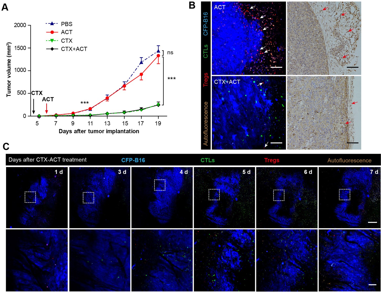
Synergistic effect of CTX and the adoptive CTLs (ACT) on CFP-B16 tumor immunotherapy.
(A) Growth curves for the CFP-B16 tumors treated with ACT, CTX or CTX-ACT and the PBS control. The data are represented as the mean ± SEM tumor volume (n = 12–14, three independent experiments). ns: not significant, ***p<0.001, (Figure 2—source data 1). (B) Intravital confocal fluorescence imaging of Tregs (red) at the tumor periphery (left panel), and immunohistochemistry (right panel) of the CFP-B16 tumor tissues after ACT (top row) or CTX-ACT (bottom row) treatment. Scale bars: 100 µm. The arrows indicate Tregs. (C) Long-term intravital imaging of the multicolor-coded tumor environment in CTX-ACT-treated mice. Red – Tregs (Foxp3-mRFP); green –CSFE-labeled CTLs; blue –CFP-B16 tumor. Top row: large-field images; scale bar: 500 µm. Bottom row: images from the region of interest in the top row; scale bar: 100 µm. The imaging data are representative of similar results from 3–5 mice in two independent experiments.
-
Figure 2—source data 1
Growth curves for the CFP-B16 tumors treated with ACT, CTX, CTX-ACT or PBS control.
- https://doi.org/10.7554/eLife.14756.010
Figure 2—figure supplement 1
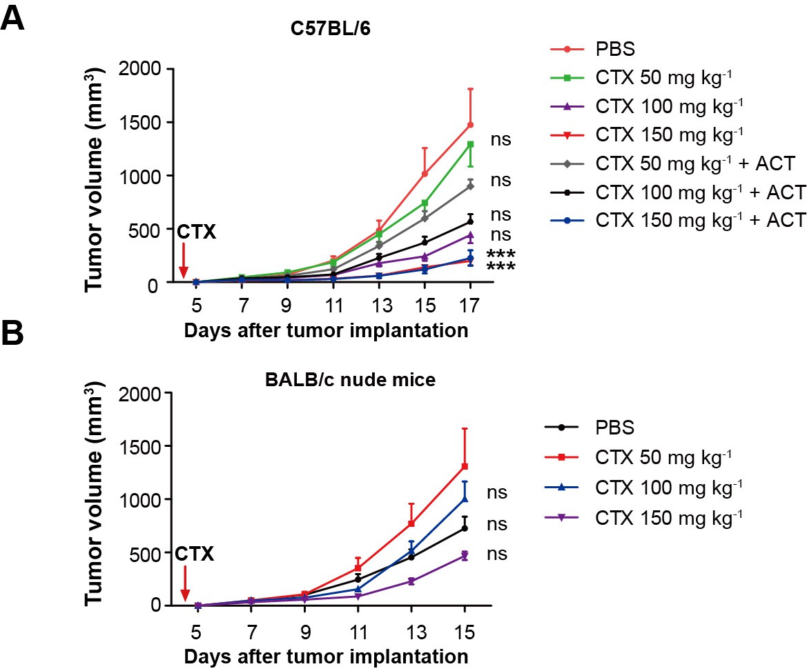
Evaluation of the effect of different doses of CTX and CTX combined with ACT on CFP-B16 tumor growth in vivo.
(A,B) Growth curves for the CFP-B16 tumors in (A) C57BL/6 and (B) BALB/c nude mice treated with different doses of CTX (50, 100 or 150 mg kg−1), different doses of CTX (50, 100 or 150 mg kg−1) combined with ACT, and PBS control. The data are represented as the mean ± SEM tumor volume (n = 9–10, two independent experiments). ***p<0.001, ns: not significant, (Figure 2—figure supplement 1—source data 1).
-
Figure 2—figure supplement 1—source data 1
Growth curves for the CFP-B16 tumors in C57BL/6 and BALB/c nude mice treated with different doses of CTX, different doses of CTX combined with ACT treatment and PBS control.
- https://doi.org/10.7554/eLife.14756.012
Figure 2—figure supplement 2

Quantification of the intravital imaging of Tregs and adoptive CTLs in ACT- and CTX-ACT-treated mice.
(A) Density of Tregs and (B) adoptive CTLs were determined by counting the number of mRFP-Tregs and CFSE-labeled CTLs per mm2 in the tumor area. The data are represented as the mean ± SEM (n = 10–12 fields, 0.40 mm2 per field) from 3–5 mice in two independent experiments. ***p<0.001, (Figure 2—figure supplement 2—source data 1).
-
Figure 2—figure supplement 2—source data 1
Density of Tregs and adoptive CTLs in the tumor area.
- https://doi.org/10.7554/eLife.14756.014
Figure 3
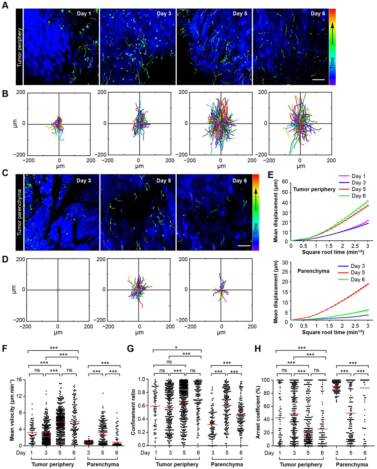
Migratory behavior of the adoptive CTLs in the tumor microenvironment of mice treated with CTX-ACT.
(A–D) Time-lapse images of CTLs with time-coded motion trajectories (color scale represents the duration). (A,C) Images of CTLs (green) at the periphery (near the blue area, A) or in the parenchyma (in the blue area, C) of the CFP-B16 tumors on different days after CTX-ACT treatment. Scale bar: 100 µm. (B,D) Trajectories of the individual CTLs at the periphery or in the parenchyma were plotted following the alignment of their starting positions. (E) Random walking analysis of the adoptive CTLs. Mean displacement (μm) versus the square root of the time (min1/2) of the CTLs at the periphery of (top) or in the parenchyma (bottom) on different days, (Figure 3—source data 1–9). (F–H) Scatter plots of (F) the mean velocity, (G) the confinement ratio, and (H) the arrest coefficient of the CTLs at the tumor periphery or in the tumor parenchyma on different days after CTX-ACT treatment. Each data point represents a single cell, and the red bars indicate mean values. *p<0.05, **p<0.01, ***p<0.001; ns – not significant, (Figure 3—source data 10). The data from 4–6 mice in three independent experiments were pooled.
-
Figure 3—source data 1
Mean displacement (μm) versus the square root of the time (min1/2) of the CTLs at the tumor periphery on Day 1.
Data listed in the excel files are displacements. Displacement is a function of time. Each column in the excel files lists displacements corresponding to one time. The time values are 0.5 min, 1 min, 1.5 min, and so on, in turn.
- https://doi.org/10.7554/eLife.14756.016
-
Figure 3—source data 2
Mean displacement (μm) versus the square root of the time (min1/2) of the CTLs at the tumor periphery on Day 3.
- https://doi.org/10.7554/eLife.14756.017
-
Figure 3—source data 3
Mean displacement (μm) versus the square root of the time (min1/2) of the CTLs at the tumor periphery on Day 5.
- https://doi.org/10.7554/eLife.14756.018
-
Figure 3—source data 4
Mean displacement (μm) versus the square root of the time (min1/2) of the CTLs at the tumor periphery on Day 6.
- https://doi.org/10.7554/eLife.14756.019
-
Figure 3—source data 5
Mean displacement (μm) versus the square root of the time (min1/2) of the CTLs in the tumor parenchyma on Day 3.
- https://doi.org/10.7554/eLife.14756.020
-
Figure 3—source data 6
Mean displacement (μm) versus the square root of the time (min1/2) of the CTLs in the tumor parenchyma on Day 5.
- https://doi.org/10.7554/eLife.14756.021
-
Figure 3—source data 7
Mean displacement (μm) versus the square root of the time (min1/2) of the CTLs in the tumor parenchyma on Day 6.
- https://doi.org/10.7554/eLife.14756.022
-
Figure 3—source data 8
Linear fitting results of MD (mean displacement) of adoptive CTLs at the tumor periphery on Day 1, Day 3, Day 5 and Day 6.
- https://doi.org/10.7554/eLife.14756.023
-
Figure 3—source data 9
Linear fitting results of MD (mean displacement) of adoptive CTLs in the tumor parenchyma on Day 3, Day 5 and Day 6.
- https://doi.org/10.7554/eLife.14756.024
-
Figure 3—source data 10
Scatter plots of the mean velocity, confinement ratio, and arrest coefficient of the adoptive CTLs at the tumor periphery or in the tumor parenchyma on different days.
- https://doi.org/10.7554/eLife.14756.025
Figure 4 with 1 supplement
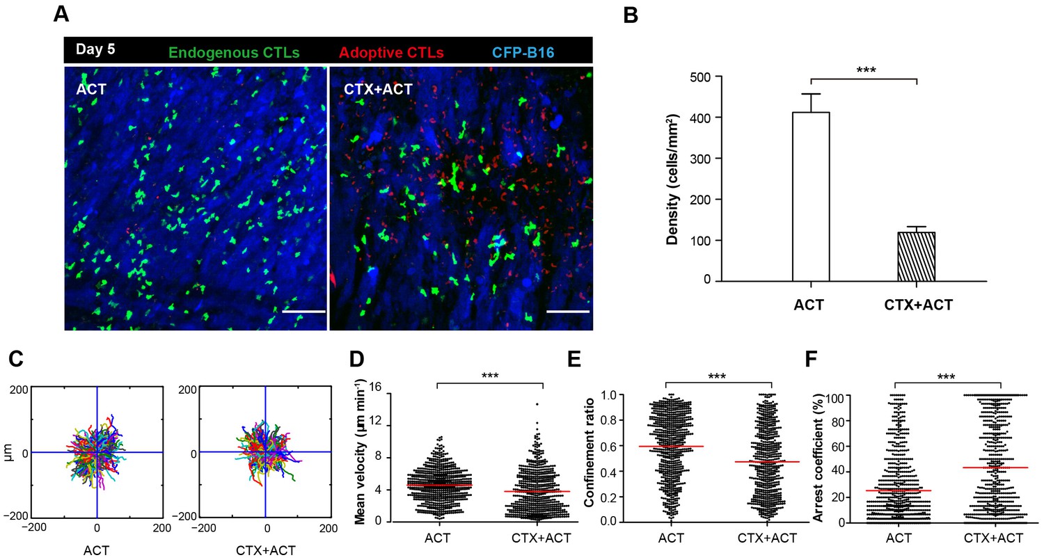
Migratory behavior of endogenous CTLs in the tumor microenvironment of mice treated with ACT and CTX-ACT on Day 5.
(A) In vivo time-lapse images of the endogenous GFP T cells (green) and adoptive CTLs (red) in the CFP-B16 tumor area (blue). Mice were treated with ACT or CTX-ACT. Scale bar: 100 μm. (B) Quantification of endogenous GFP T cells in the differently treated groups on Day 5. Results are represented as the mean ± SEM (n = 11–19 fields, 0.40 mm2 per field) from three mice per group. ***p<0.001 (Figure 4—source data 1). (C) Trajectories of GFP T cells in the differently treated groups were plotted following the alignment of their starting positions. (D–F) Scatter plots of (D) the mean velocity, (E) the confinement ratio, and (F) the arrest coefficient of the GFP T cells in tumor areas in the differently treated groups on Day 5. Each data point represents a single cell, and the red bars indicate mean values. *p<0.05, **p<0.01, ***p<0.001; ns: not significant (Figure 4—source data 2). The data from 3–5 mice in two independent experiments were pooled.
-
Figure 4—source data 1
Quantification of endogenous GFP T cells in the differently treated groups on Day 5.
- https://doi.org/10.7554/eLife.14756.031
-
Figure 4—source data 2
Scatter plots of the mean velocity, confinement ratio, and arrest coefficient of the GFP T cells in tumor areas in the differently treated groups on Day 5.
- https://doi.org/10.7554/eLife.14756.032
Figure 4—figure supplement 1
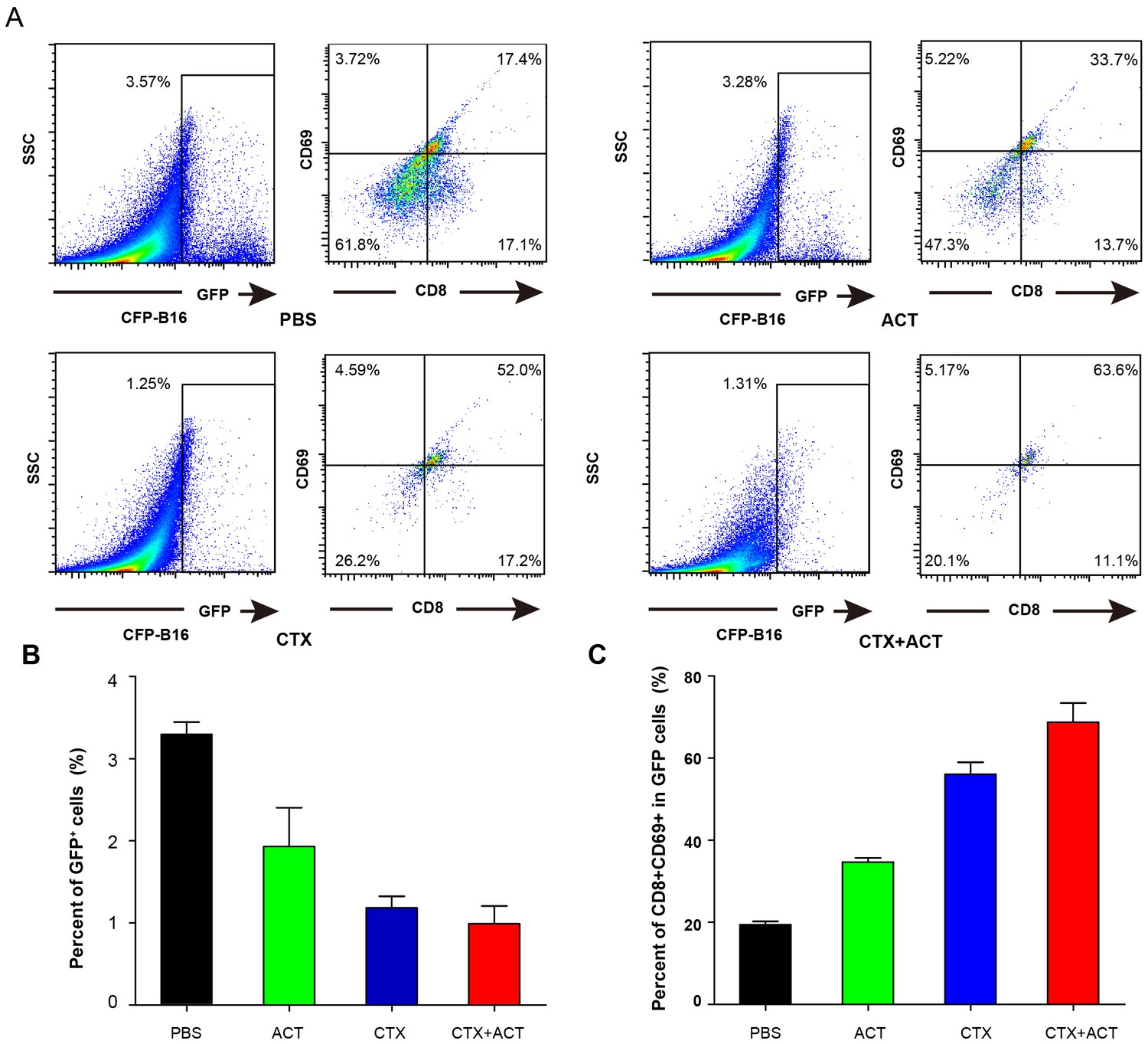
Characterization of GFP cells in differently treated Cxcr6+/gfp mice.
(A) Ex vivo analysis and characterization of the GFP cells in the tumors of Cxcr6+/gfp mice that were treated differently. (B) Percentage of GFP cells in the tumors of mice following the different treatments. (C) Percentage of CD8+CD69+ CTLs in the GFP cells from (B).
Figure 5
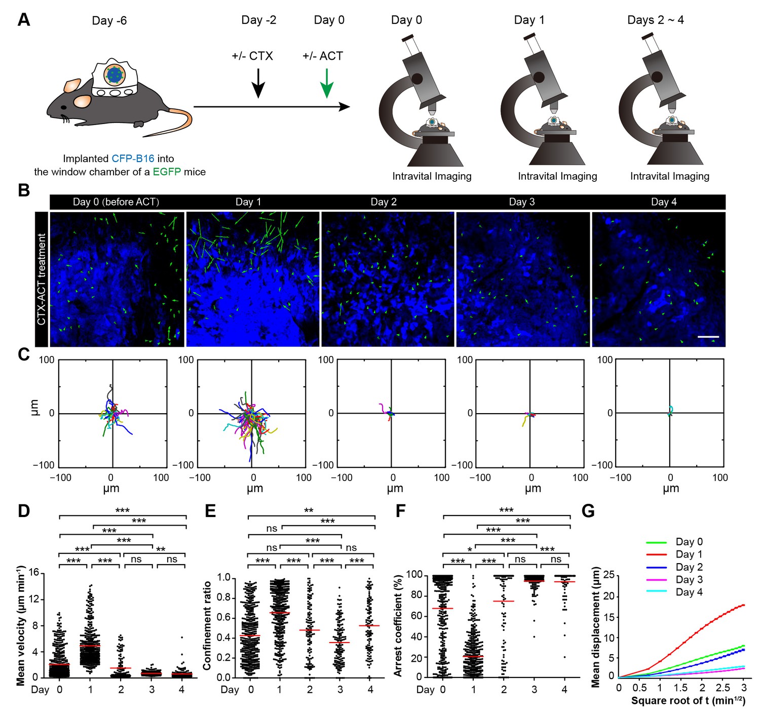
Migratory behavior of endogenous tumor-infiltrating immunocytes (TIIs) induced by the CTX-ACT treatment.
(A) Experimental procedure for long-term intravital imaging of TIIs in the tumor microenvironment. (B) In vivo time-lapse images of EGFP TIIs (green) in the CFP-B16 tumor area (blue) from Day 0 to Day 4 after CTX-ACT treatment. Green arrows represent TIIs displacement, and blue areas represent CFP-B16 tumors. Scale bar: 100 µm. (C) Trajectories of individual TIIs on different days were plotted following the alignment of their starting positions. (D–F) Scatter plots of the (D) mean velocity, (E) confinement ratio, and (F) arrest coefficient of EGFP TIIs in tumor areas on different days. Each data point represents a single cell, and the red bars indicate mean values. *p<0.05, **p<0.01, ***p<0.001; ns, not significant, (Figure 5—source data 1). (G) Random walking analysis of the TIIs on different days. Mean displacement (μm) versus the square root of the time (min1/2) of the TIIs, (Figure 5—source data 2–7). The data from 4–7 mice in three independent experiments were pooled.
-
Figure 5—source data 1
Scatter plots of the mean velocity, confinement ratio, and arrest coefficient of EGFP TIIs in tumor areas on different days.
- https://doi.org/10.7554/eLife.14756.036
-
Figure 5—source data 2
Mean displacement (μm) versus the square root of the time (min1/2) of the TIIs on Day 0.
Data listed in the excel files are displacements. Displacement is a function of time. Each column in the excel files lists displacements corresponding to one time. The time values are 0.5 min, 1 min, 1.5 min, and so on, in turn.
- https://doi.org/10.7554/eLife.14756.037
-
Figure 5—source data 3
Mean displacement (μm) versus the square root of the time (min1/2) of the TIIs on Day 1.
- https://doi.org/10.7554/eLife.14756.038
-
Figure 5—source data 4
Mean displacement (μm) versus the square root of the time (min1/2) of the TIIs on Day 2.
- https://doi.org/10.7554/eLife.14756.039
-
Figure 5—source data 5
Mean displacement (μm) versus the square root of the time (min1/2) of the TIIs on Day 3.
- https://doi.org/10.7554/eLife.14756.040
-
Figure 5—source data 6
Mean displacement (μm) versus the square root of the time (min1/2) of the TIIs on Day 4.
- https://doi.org/10.7554/eLife.14756.041
-
Figure 5—source data 7
Linear fitting results of MD (Mean displacement) of TIIs at tumor areas on Day 0–Day 4.
- https://doi.org/10.7554/eLife.14756.042
Figure 6 with 1 supplement
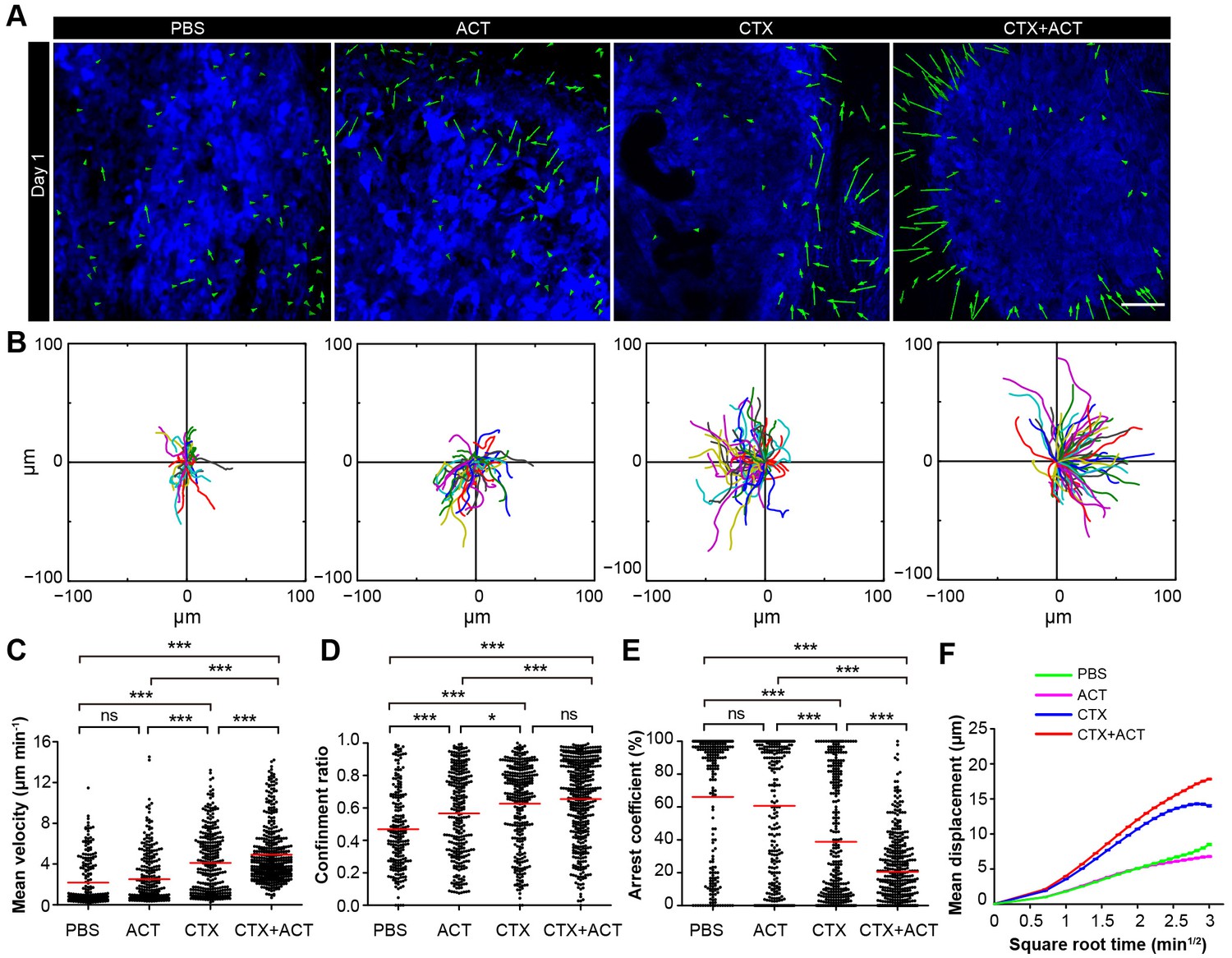
Migratory behavior of the TIIs following different treatments.
(A) In vivo time-lapse images of the EGFP TIIs in the CFP-B16 tumor area on Day 1. Mice were treated with ACT, CTX, CTX-ACT or PBS control. Green arrows represent TIIs displacement, and blue areas represent CFP-B16 tumors. Scale bar: 100 µm. (B) The trajectories of individual EGFP TIIs in different treated groups were plotted following the alignment of their starting positions. (C–E) Scatter plots of the (C) mean velocity, (D) confinement ratio, and (E) arrest coefficient of the EGFP TIIs in the differently treated groups. Each data point represents a single cell, and the red bars indicate mean values. *p<0.05, **p<0.01, ***p<0.001; ns, not significant (Figure 6—source data 1). (F) Random walking analysis of the TIIs in the different groups. Mean displacement (μm) versus the square root of time (min1/2) of TIIs in different treatment groups ( Figure 6—source data 2–6). The data from 12–15 mice in three independent experiments were pooled.
-
Figure 6—source data 1
Scatter plots of the mean velocity, confinement ratio, and arrest coefficient of the EGFP TIIs in the different treatment groups.
- https://doi.org/10.7554/eLife.14756.045
-
Figure 6—source data 2
Mean displacement (μm) versus the square root of the time (min1/2) of the TIIs in the PBS group.
Data listed in the excel files are displacements. Displacement is a function of time. Each column in the excel files lists displacements corresponding to one time. The time values are 0.5 min, 1 min, 1.5 min, and so on, in turn.
- https://doi.org/10.7554/eLife.14756.046
-
Figure 6—source data 3
Mean displacement (μm) versus the square root of the time (min1/2) of the TIIs in the ACT group.
- https://doi.org/10.7554/eLife.14756.047
-
Figure 6—source data 4
Mean displacement (μm) versus the square root of the time (min1/2) of the TIIs in the CTX group.
- https://doi.org/10.7554/eLife.14756.048
-
Figure 6—source data 5
Mean displacement (μm) versus the square root of the time (min1/2) of the TIIs in the CTX-ACT group.
- https://doi.org/10.7554/eLife.14756.049
-
Figure 6—source data 6
Linear fitting results of MD (Mean displacement) of TIIs at tumor areas in the different treatment groups on Day 1.
- https://doi.org/10.7554/eLife.14756.050
Figure 6—figure supplement 1
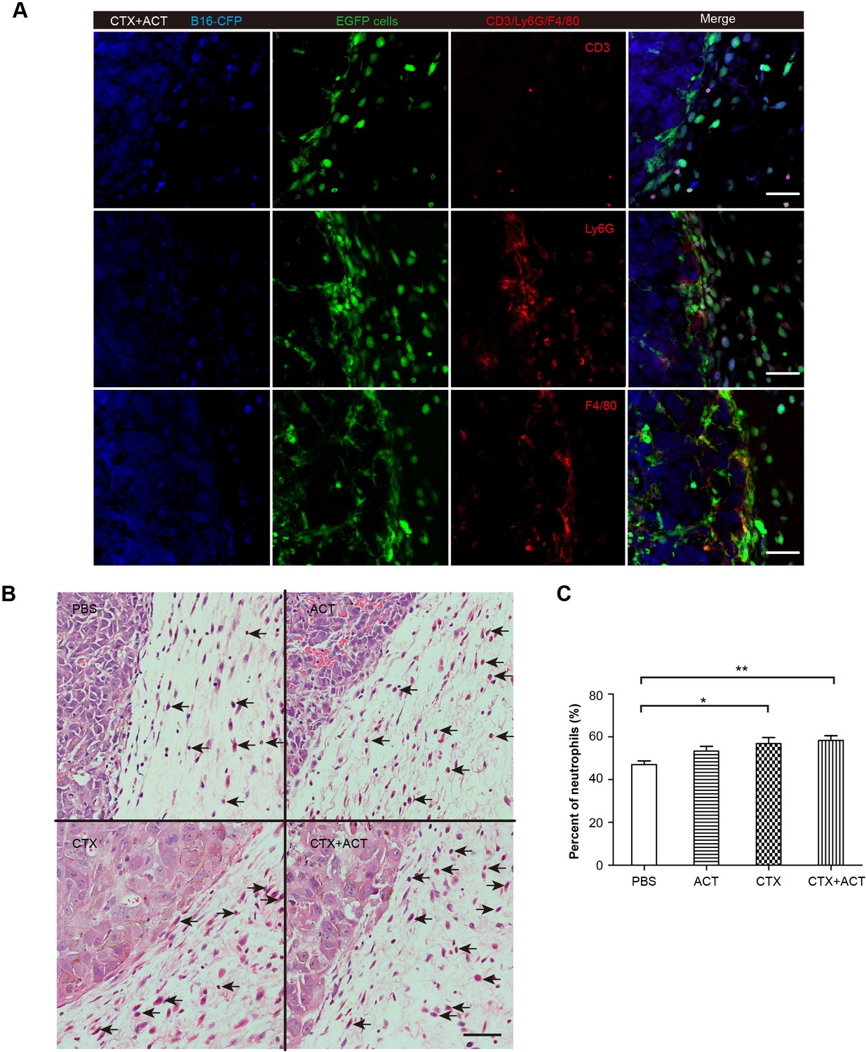
Phenotype of EGFP TIIs in CFP-B16 tumors of mice following different treatments.
(A) Representative tumor sections stained with CD3, Ly6G and F4/80. Most of the EGFP TIIs at the tumor periphery were Ly6G+ and F4/80+. Scale bar: 50 μm. (B) Histopathology of HE-stained tumor sections from tumor-bearing mice exposed to different treatments. Black arrows indicate neutrophils. Scale bar: 50 μm. (C) Percentage of neutrophils among TIIs at the periphery of the tumors in mice that received different treatments. The data are represented as the mean ± SEM (n = 14–20 fields) results from three mice per group. *p<0.05, **p<0.01, (Figure 6—figure supplement 1—source data 1).
-
Figure 6—figure supplement 1—source data 1
Percentage of neutrophils among TIIs at the periphery of the tumors in mice that received different treatments.
- https://doi.org/10.7554/eLife.14756.052
Figure 7
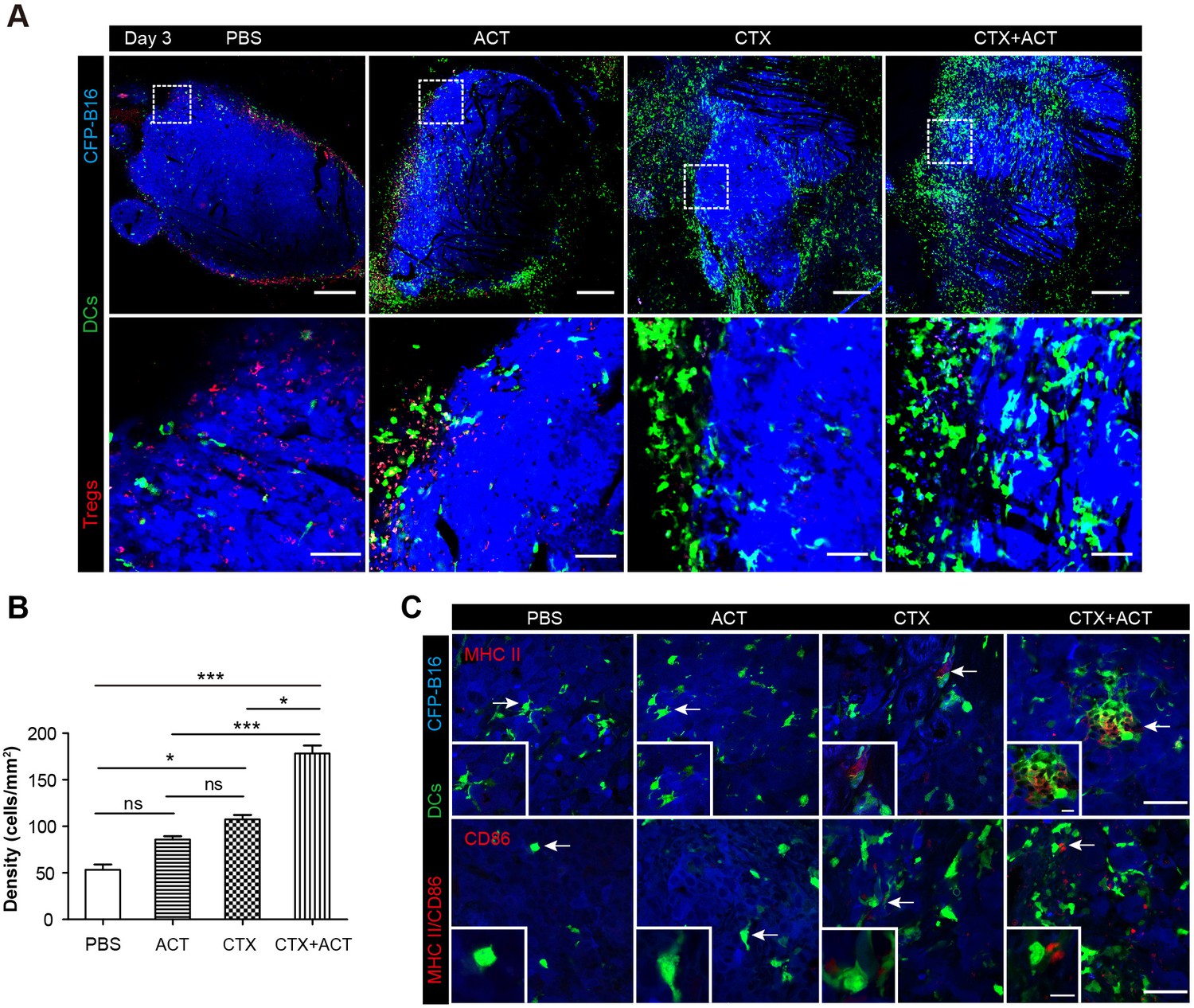
Intravital imaging of DCs infiltrating into the tumor areas of the mice following different treatments.
(A) Large-field intravital imaging of DCs (green) and Tregs (red) in the CFP-B16 tumor area (blue) on Day 3. Top row: large-field images; scale bar 500 µm. Bottom row: images of the region of interest from the top row; scale bar 100 µm. (B) Density of DCs in the tumor areas in the different treatment groups. The data are represented as the mean ± SEM (n = 10–14 fields, 12 mm2 per field (large-field images) or 0.40 mm2 per field) from three independent experiments. *p<0.05, **p<0.01, ***p<0.001; ns, not significant (Figure 7—source data 1). (C) Representative images of mature DCs in tumor sections were immunofluorescently labeled to detect MHC II (top row) and CD86 (bottom row). Scale bar: 40 µm. Inserts are magnifications of the regions indicated with arrows. Scale bar: 15 µm.
-
Figure 7—source data 1
Density of DCs in the tumor areas in the different treatment groups.
- https://doi.org/10.7554/eLife.14756.055
Figure 8
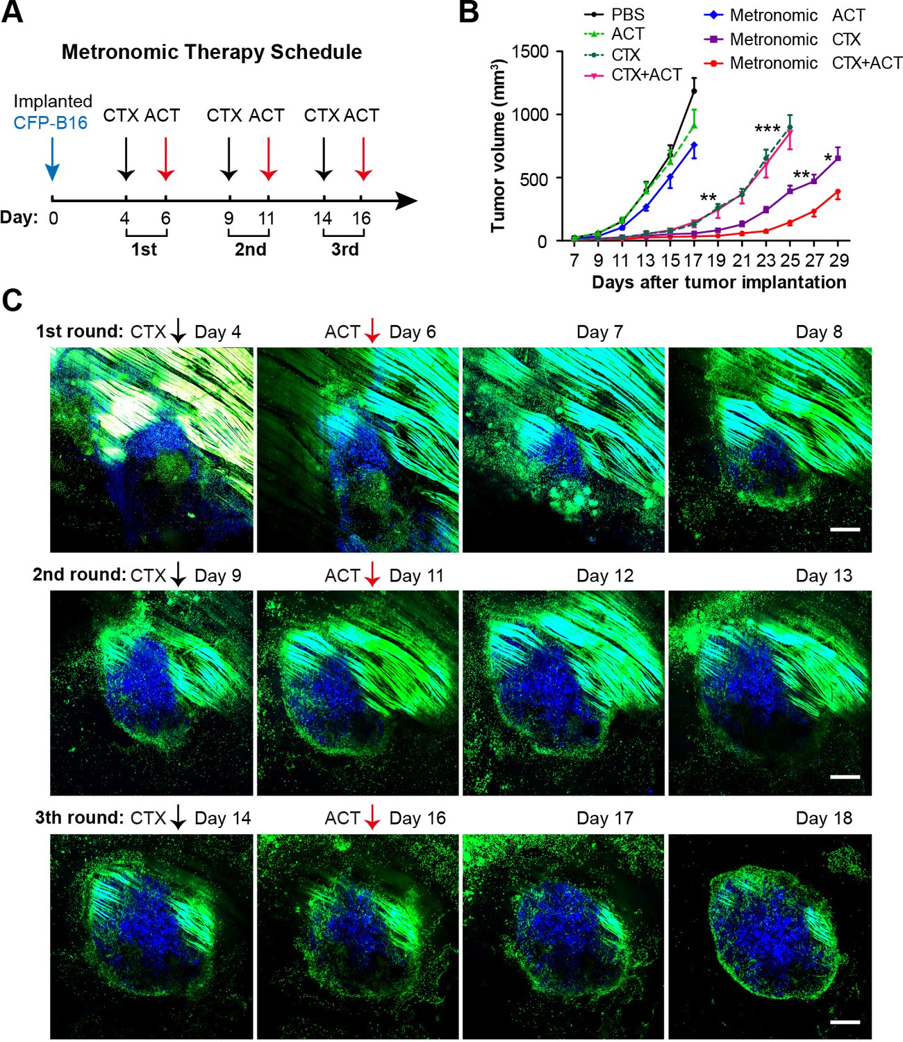
Metronomic CTX-ACT therapy efficiently controlled the growth of CFP-B16 tumors in vivo.
(A) Metronomic therapy schedule of the CTX-ACT treatment. (B) Growth curves for CFP-B16 tumors in the different treatment groups. The data are represented as the mean ± SEM tumor volume (n = 12–15, three independent experiments). *p<0.05, **p<0.01, ***p<0.001(Figure 8—source data 1). (C) Long-term and large-field intravital images of the tumor microenvironment during CTX-ACT metronomic therapy. Blue, a CFP-B16 tumor; green, EGFP host cells. Scale bar: 500 µm.
-
Figure 8—source data 1
Growth curves for CFP-B16 tumors in the different treatment groups
- https://doi.org/10.7554/eLife.14756.057
Figure 9

Timeline schematic showing the elicitation of anti-tumor immune responses in the tumor microenvironment by CTX-ACT treatment.
Step 1: CFP-B16 tumor cells grew and Tregs accumulated in the tumor area before CTX treatment. Step 2: CTX treatment depleted most Tregs, blocking the formation of an ‘immunosuppressive ring’. Step 3: A transient increase in the motility of the endogenous neutrophils is elicited by CTX-ACT treatment on Day 1. Step 4: DCs present increased infiltration on Day 3. Step 5: Adoptive CTLs present increased infiltration and motility and the CTX-ACT treatment retained activated endogenous CTLs in the tumor area on Day 5. Step 6: Solid tumor ‘melting' occurs from the inside and 'shrinking’ occurs from the outside on Days 5–6.
Author response image 1
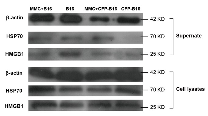
Western blot of DAMPs expression in supernatants or whole-cell lysates of mitomycin C treated B16 cells, non-mitomycin C-treated B16 cells, mitomycin C-treated CFP-B16 cells, and non-mitomycin C-treated CFP-B16 cells.
Supernatants are normalized to the cell numbers.
Author response image 2
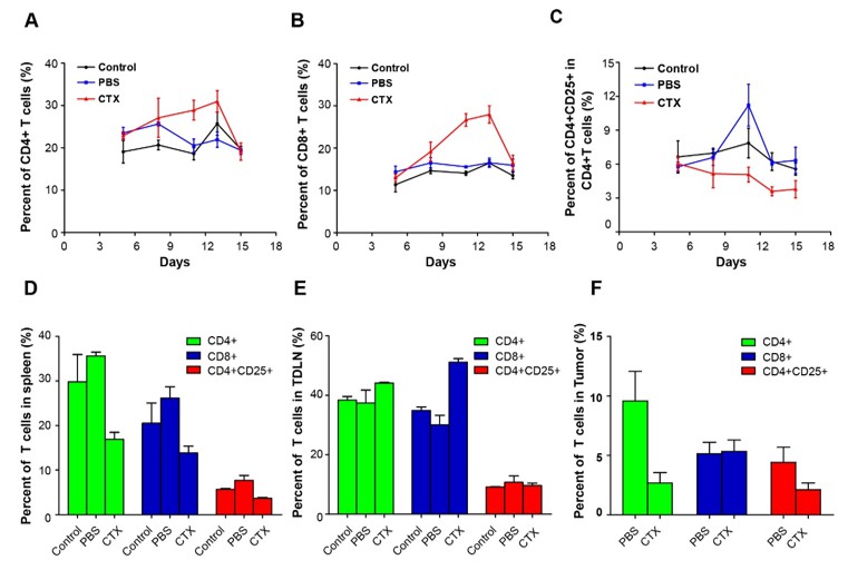
Alterations in T cell subsets caused by CTX treatment.
Top row: percentage changes of CD4+ cells, CD8+ T cells, and CD4+CD25+ Tregs in the blood of normal mice, PBS-treated tumor-bearing mice, and CTX metronomically treated tumor-bearing mice on days 5, 7, 11, 13, and 15 after implantation of tumor cells. Bottom row: percentage changes of CD4+ cells, CD8+ T cells, and CD4+CD25+ Tregs in different organs (spleen, TDLN, and tumor) of normal mice, PBS-treated tumor-bearing mice, and CTX t metronomically treated tumor-bearing mice on day 15.
Author response image 3
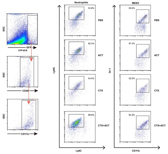
Characterization of the neutrophils and MDSCs of EGFP TIIs ex vivo by flow cytometry.
The markers of neutrophils are CD11b+Ly6G+Ly6Clow, and markers of MDSCs are CD11b+Gr1+.
Author response image 4

Representative tumor sections stained with CD3, CD4, CD8, Ly6G and F4/80.
Most of the EGFP TIIs at the tumor periphery were Ly6G+ and F4/80+. Scale bar: 50 μm.
Videos
Video 1
In vivo sequential imaging of adoptive CTLs at the periphery and in the parenchyma of CFP-B16 tumors on Day 1 (after CTX-ACT treatment).
The 3D time-lapse images were acquired as a 30 μm z-stack. Adoptively transferred CTLs are shown in green (CFSE-labeled), and the B16 tumor cells are shown in blue (CFP). Scale bar: 70 μm.
Video 2
In vivo sequential imaging of adoptive CTLs at the periphery and in the parenchyma of CFP-B16 tumors on Day 3.
The 3D time-lapse images were acquired as a 30 μm z-stack. Adoptively transferred CTLs are shown in green (CFSE-labeled), and the B16 tumor cells are shown in blue (CFP). Scale bar: 70 μm.
Video 3
In vivo sequential imaging of adoptive CTLs at the periphery and in the parenchyma of CFP-B16 tumors on Day 5.
The 3D time-lapse images were acquired as a 30 μm z-stack. Adoptively transferred CTLs are shown in green (CFSE-labeled), and the B16 tumor cells are shown in blue (CFP). Scale bar: 70 μm.
Video 4
In vivo sequential imaging of adoptive CTLs at the periphery and in the parenchyma of CFP-B16 tumors on Day 6.
The 3D time-lapse images were acquired as a 30 μm z-stack. Adoptively transferred CTLs are shown in green (CFSE-labeled), and the B16 tumor cells are shown in blue (CFP). Scale bar: 70 μm.
Video 5
In vivo sequential imaging of endogenous T cells and adoptive CTLs in CFP-B16 tumor areas in mice exposed to ACT and CTX-ACT combined treatments on Day 5.
Time-lapse images were collected for 15 min. Endogenous T cells are shown in green (GFP labeled), adoptive CTLs are shown in red (CMTPX labeled) and the B16 tumor cells are shown in blue (CFP labeled). Scale bar: 100 μm.
Video 6
In vivo sequential imaging of endogenous TIIs at the periphery of the CFP-B16 tumors on different days following treatment with CTX and ACT.
Time-lapse images were collected for 10 or 15 min. Endogenous TIIs are shown in green (EGFP), and the B16 tumor cells are shown in blue (CFP). Scale bar: 70 μm.
Video 7
In vivo sequential imaging of endogenous TIIs at the periphery of the CFP-B16 tumors on Day 1 in mice exposed to different treatments.
Time-lapse images were collected for a duration of 10 or 15 min. Mice were mock-treated (with PBS) or treated with CTX, ACT, or CTX-ACT as indicated. Endogenous TIIs are shown in green (EGFP-labeled) and the B16 tumor cells are shown in blue (CFP-labeled). Scale bar: 70 μm.
Additional files
-
Source code 1
The CellTracking_GUI.m is the main program of the Post-TrackObject software.
The Post-TrackObject software is designed based on the Matlab (R2012, MathWorks) GUI.
- https://doi.org/10.7554/eLife.14756.059
-
Source code 2
The CellTracking_GUI.fig is the main user interface of the Post-TrackObject software
- https://doi.org/10.7554/eLife.14756.060
-
Source code 3
The CellTracking_GUI_Trajectory.m is the subprogram of the Post-TrackObject software
- https://doi.org/10.7554/eLife.14756.061
-
Source code 4
The conrat.m is the subprogram of the Post-TrackObject software
- https://doi.org/10.7554/eLife.14756.062
-
Source code 5
The dmean_motcoe.m is the subprogram of the Post-TrackObject software
- https://doi.org/10.7554/eLife.14756.063
-
Source code 6
The mdmot_eb.m is the subprogram of the Post-TrackObject software
- https://doi.org/10.7554/eLife.14756.064
-
Source code 7
The mean_sem.m is the subprogram of the Post-TrackObject software
- https://doi.org/10.7554/eLife.14756.065
-
Source code 8
The trajectory.m is the subprogram of the Post-TrackObject software
- https://doi.org/10.7554/eLife.14756.066
-
Source code 9
The vmean_arrcoe.m is the subprogram of the Post-TrackObject software
- https://doi.org/10.7554/eLife.14756.067
-
Source code 10
The CellTracking_GUI_Trajectory.fig is the subinterface which corresponds to the subprogram CellTracking_GUI_Trajectory.m.
- https://doi.org/10.7554/eLife.14756.068
Download links
A two-part list of links to download the article, or parts of the article, in various formats.
Downloads (link to download the article as PDF)
Open citations (links to open the citations from this article in various online reference manager services)
Cite this article (links to download the citations from this article in formats compatible with various reference manager tools)
Long-term intravital imaging of the multicolor-coded tumor microenvironment during combination immunotherapy
eLife 5:e14756.
https://doi.org/10.7554/eLife.14756


