Abstract
Aims: To define the optimal kissing balloon inflation (KBI) after single-stent deployment in a coronary bifurcation model.
Methods and results: We deployed stents in main vessels (MV) followed by KBI in various conditions and compared the stent configurations. A) KBI at the operator’s discretion vs. under the guidelines of minimal balloon overlapping (MBO). Various stent configurations were observed after the former option, whereas similar maximal dilation points were observed under the MBO guidelines. B) Long balloon overlapping (LBO) vs. MBO with proximal MV dilated by a large balloon. The proximal MV was dilated to an ideal round shape with MBO versus an oval shape with LBO. C) Two-link vs. 3-link stents. Although the 2-link stent was advantageous to open the side branch, it incurred a risk of overdilatation of the proximal struts, whereas the 3-link stent preserved its structure. Computed simulations of coronary flow were analysed in the following left main coronary models: circle with a diameter of 4 and 5.5 mm, ellipse with longitudinal direction and tilt position. They revealed that the overdilated side was exposed to low shear stress regardless of its shape.
Conclusions: Optimal KBI can be achieved with MBO and proximal dilatation by an optimally sized balloon.
Abbreviations
DES: drug-eluting stent
LBO: long balloon overlapping
KBI: kissing balloon inflation
MACE: major adverse cardiac events
MBO: minimal balloon overlapping
MFCT: microfocus x-ray computed tomography
MV: main vessel
SB: side branch
Introduction
Despite the use of drug-eluting stents (DES), coronary bifurcation lesions remain associated with high rates of restenosis and stent thrombosis1,2. The deployment of stents in both the main vessel (MV) and the side branch (SB) with a view to covering the entire lesion conferred no benefit compared with the deployment of a single stent in the MV3,4. Therefore, a provisional stent strategy has been recommended as first-line treatment5. However, the indications and SB characteristics, including degree of stenosis, perfusion area, size, and flow disturbance, remain controversial.
Kissing balloon inflation (KBI) has been advocated for the management of bifurcation lesions6 in order to: 1) preserve the access to the SB; 2) prevent its narrowing and restenosis; 3) widen the lumen of the proximal MV; 4) optimise the stent apposition; and 5) minimise the stent deformation. While the efficacy of KBI as a means of limiting restenosis of the SB in dual stent deployment has been demonstrated conclusively7-9, its effect on the rates of major adverse cardiac events (MACE) when a single stent is deployed has recently been questioned. The Nordic-Baltic III trial, in which patients undergoing deployment of a single stent in the MV were randomly assigned to final KBI versus no KBI, observed identical 2.9% MACE rates in both study groups10. In the Korean Coronary Bifurcation Stenting (COBIS) Registry, KBI was associated with a higher MACE rate (8.7%) than no KBI (4.7%)11.
In a study comparing fractional flow reserve versus quantitative coronary angiography, the angiographic severity of the jailed SB was often overestimated, as a FFR <0.75 was observed in only 27% of SB with >75% angiographic stenosis12. Therefore, overtreatment of the SB is thought to be one of the explanations for the adverse consequences of KBI. However, in both the Nordic-Baltic III trial and the COBIS Registry, numerically higher rates of restenosis in the MV in the KBI group were observed compared to the non-KBI group, whereas there were lower rates in the SB10,11. In addition, oval stent deformation in the proximal MV is induced by KBI13, which does not obey the natural vascular branching law and symmetric property. Thus, the adverse effects of KBI are not explained only by overtreatment of SB, but also by disturbances in the MV.
To clarify the effects of KBI on the MV, we studied the deformation of stents implanted by crossover stenting followed by KBI in a bifurcation phantom model, using microfocus x-ray computed tomography (MFCT) with a superior resolution14,15. We also performed a computer-based analysis of the coronary flow in the deformed stents in order to clarify the benefit of proximal optimisation of the proximal MV after KBI.
Methods
BENCH TESTING
EFFECTS OF BALLOON CONFIGURATION ON THE STENT DEFORMATION
A 3.5 mm MULTI-LINK ZETA stent (Abbott Vascular, Santa Clara, CA, USA) was deployed by six separate operators, crossing over the SB in a two-dimensional (2-D) bifurcation phantom model. KBI was performed with two 3.0/20.0 mm balloons (CROSSSAIL®; Abbott Vascular) according to each operator’s choice with respect to the location of the SB balloon, balloon overlapping, and inflation pressure. Magnified digital photographs were taken at the time of inflation to examine the deformation of the MV stent. Crossover stenting followed by KBI was performed by four other operators instructed to minimise the balloon overlapping with 2-3 mm of the protrusion from the ostium of each branch, and the outcome was compared with the previously described stent implantation. A polyvinyl acetate tube was used in the silicon mould to obtain clear images of the balloons.
LONG VERSUS MINIMAL BALLOON OVERLAPPING WITH DILATATION OF THE PROXIMAL MV BY A LARGE SHORT BALLOON
To compare minimal (MBO) with long (LBO) balloon overlapping, KBI with 3.5/20 and 3.0/20 mm balloons (CROSSSAIL) was performed after crossover stenting, using a 3.5 mm MULTI-LINK VISION™ stent (Abbott Vascular) in the same 2-D models as the previous experiment, with 30, 50, and 60 degree bifurcation angles. In the MBO group, the balloons were positioned such that they overlapped by 2-3 mm and were simultaneously dilated at 8 atm after sequential inflation at 12 atm. The proximal MV was then dilated with a 4.5/8 mm balloon (Quantum Maverick®; Boston Scientific, Natick, MA, USA) at 12 atm (Figure 1A). In the LBO group, 3.5 and 3.0 mm balloons of the same type were positioned at the proximal stent edge and dilated simultaneously at 8 atm after sequential dilatation (Figure 1B). The configuration of the stent was analysed using MFCT (inspeXio SMX-225CT; Shimadzu, Kyoto, Japan) as previously described14,15. The MFCT images were acquired at 0.12 mm intervals and pitched at 0.06 mm, and the digitised images were reconstructed in three dimensions, using the VG studio MAX 1.2 graphic software (Volume Graphics GmbH, Heidelberg, Germany). Cross-sectional area and eccentric index, defined as the ratio of short axis diameter to the long axis one, were measured and calculated at the proximal edge, middle point of the proximal part of the stent, carina, and distal edge of the dilated stent.
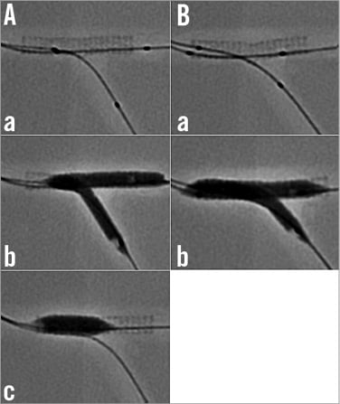
Figure 1. Bench comparisons of minimal (MBO) versus long (LBO) balloon overlapping during KBI. A) MBO. a) Location of 3.5 and 3.0 mm balloons in the bifurcation model, where a 3.5 mm stent was deployed in the MV; b) simultaneous inflation; c) proximal MV dilation with a 4.5/8 mm balloon. B) LBO. a) Location of 3.5 and 3.0 mm balloons; b) simultaneous inflation.
COMPARISON BETWEEN 2-LINK AND 3-LINK STENTS
Crossover stenting followed by KBI was performed in a three-dimensional, Y-shaped bifurcation model, in which silicon tubes angled at 60º were attached to the silicon block arc-shaped at a 120º angle. Endeavor® 3.5/24 mm (Medtronic Inc., Minneapolis, MN, USA) and MULTI-LINK ZETA 3.5/28 mm (Abbott Vascular) stents were used as representatives of 2-link and 3-link stents, respectively. In the KBI, 3.5/20 mm and 3.0/20 mm balloons (Ryujin™ Plus; Terumo, Tokyo, Japan) were simultaneously dilated at 8 atm, after sequential balloon dilatation at 12 atm, with their proximal segments placed in the proximal edge of the stent. The stent configuration was analysed, using MFCT.
COMPUTER-BASED ANALYSIS OF THE CORONARY FLOW
The effect of proximal overdilatation by KBI on the coronary flow dynamics in the left main (LM) coronary artery bifurcation was analysed in the computational flow dynamics. The LM bifurcation model included: A) a 15 mm long LM coronary artery, B) a left anterior descending artery with a diameter of 3.5 mm, and C) a circumflex artery with a diameter of 3.0 mm, with these two vessels bifurcated at an angle of 120º. The simulated LM artery was connected to the aorta with a radius of 5 mm, the simulated systolic flow was 40% of the diastolic flow and the direction of forward flow was in the opposite direction to the diastolic flow. The coronary flow was simulated by a finite volume method, using the ANSYS CFX12.0 software package (Cybernet Systems, Tokyo, Japan). Peak systolic and diastolic flow velocity were measured in the LM coronary artery under the following conditions: A) circle with a diameter of 4 mm, B) circle with a diameter of 5.5 mm, C) ellipse with long and short diameters of 5.5 and 4 mm, respectively, with its long axis in a longitudinal direction (ellipse - longitude), and D) ellipse with the same dimension as in C, with its long axis in the tilt position (ellipse - tilt).
Results
BENCH TESTING
EFFECT OF BALLOON CONFIGURATION ON THE STENT DEFORMATION
In the model where KBI was left to the operator’s discretion, various proximal MV stent configurations were observed, since they were dependent on the operator’s choice of proximal position of the respective balloons and of their overlap. As shown in Figure 2A, the proximal position of the SB balloon varied in the proximal part (a, b, c and f) and in the distal part (d and e). The points of maximal dilatation (arrows) varied widely among the six experiments (a, b, d: proximal edge of the SB, c: just proximal to the bifurcation, e: widely existed in the proximal MV). In contrast, they were similarly located just proximal to the bifurcation in the experiments where KBI was performed under the guidelines of MBO (Figure 2B).
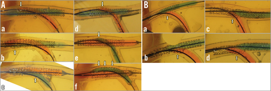
Figure 2. Balloon overlapping in KBI. A) At the operator’s discretion. Note the various configurations of the proximal MV stent depending on the location of the proximal site of the SB balloon (a, b, c, f: proximal part; d, e: distal part). The white arrows show the maximal dilation points that varied among the 6 experiments (a, b, d: proximal edge of the SB; c: just proximal to the bifurcation; e: widely existed in the proximal MV). B) With the MBO guidelines. Maximally dilated points (white arrows) are consistently just proximal to the bifurcation site.
LBO VS. MBO WITH THE PROXIMAL MV DILATED BY A LARGE, SHORT BALLOON
In the MBO group, the degree of stent expansion at the ostium of the SB was similar, regardless of the bifurcation angle (Figure 3A, pink arrows). In contrast, in the LBO group, the degree of stent expansion increased with the bifurcation angle, which modified the balloon overlapping from a lateral to a longitudinal position (Figure 3B, yellow arrows). In the 60-degree angle model, the minimally overlapping stent remained uniformly expanded proximally, whereas the prominently overlapping stent was deformed in an oval shape (Figure 4Aa and Figure 4Ab vs. Figure 4Ba and Figure 4Bb, Moving image 1 vs. Moving image 2, Moving image 3 vs. Moving image 4). As shown in Figure 5, similar symmetric stent expansion was obtained in the proximal MV (% change of cross-sectional area: 120-140%, eccentric index: 0.9-1.0) regardless of the difference in the bifurcation angle in the MBO group, while varied asymmetric expansion was observed in the LBO group (% change of cross-sectional area: 110-150%, eccentric index: 0.6-0.9).
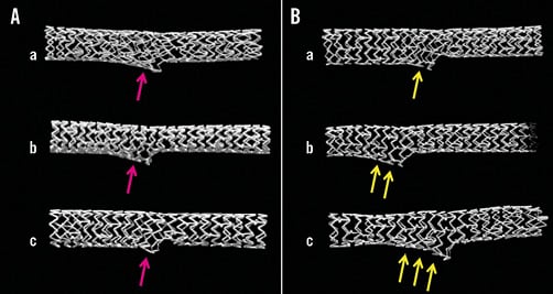
Figure 3. MFCT images of stent configuration after KBI with bifurcation angle at 30 (a), 50 (b), and 60 degrees (c). A) MBO. B) LBO. Note the difference in the stent deformation at the SB. More deformation was observed according to the bifurcation angle in LBO (yellow arrows) compared to a similar change in MBO (pink arrows).
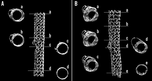
Figure 4. Cross-sectional MFCT images of stent configuration after KBI with 60-degree bifurcation angle. A) MBO. B) LBO. Note round shape stent dilation in the MBO vs. oval shape in the LBO in the proximal MV. The oval shapes in each cross-section varied in the LBO (B: a-d).
COMPARISON BETWEEN 2-LINK AND 3-LINK STENTS
With both types of stents, the proximal MV was dilated to an oval shape. As the long axis of the oval shape indicates, the balloon overlap changed from a lateral to a longitudinal orientation. Since the Endeavor stent was a coil with 2 links, the space between the struts was prominently widened in the proximal overdilated MV (Figure 6A-Figure 6C, Moving image 5). In contrast, the structural integrity of the 3-link MULTI-LINK stent was preserved, including at the site dilated to an oval shape (Figure 7A-Figure 7C, Moving image 6). At the SB ostium, the jailed struts of the 2-link stent were completely separated (Figure 6D), whereas, in the 3-link stent, the jailed strut remained at the site where the SB balloon crossed over the MV balloon (Figure 7D and Figure 7E).
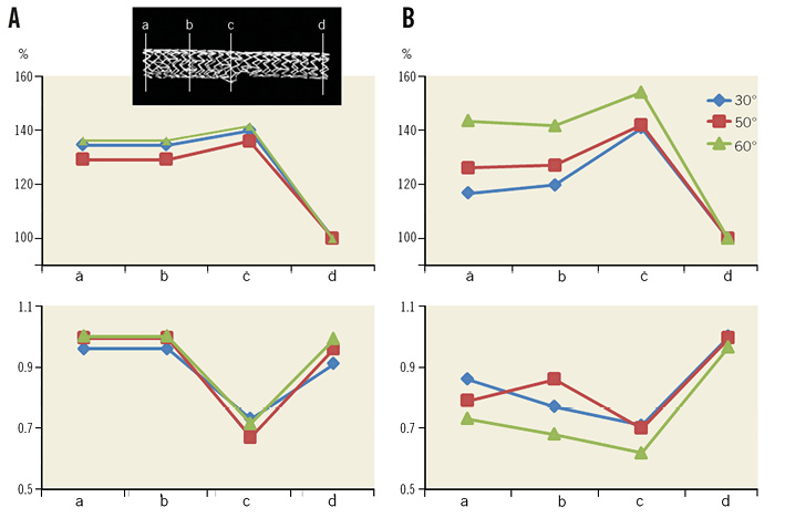
Figure 5. Comparison in cross-sectional area and eccentric index of the stent after KBI with MBO and LBO with bifurcation angle at 30, 50, and 60 degrees. A) Percent change of cross-sectional area at proximal edge (a), middle point of the proximal part of the stent (b), carina (c), and distal edge (d). Left: MBO. Right: LBO. The area at the distal edge of the stent was regarded as 100%. B) Eccentric index. Note that similar stent expansion was obtained by MBO.
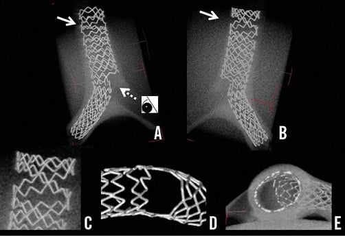
Figure 6. Images of Endeavor stent with 2-link connection deployed in a 3-dimensional Y-shaped model. A) View from the top. B) View from the bottom. C) Magnified view of overdilatation of the proximal struts outlined by the arrows in panels A) and B). D) Magnified view of the LCX ostium, after complete removal of the jailed struts, from the vantage point shown by the dotted arrow in panel A). E) Cross-sectional view from the inner side at the bifurcation.
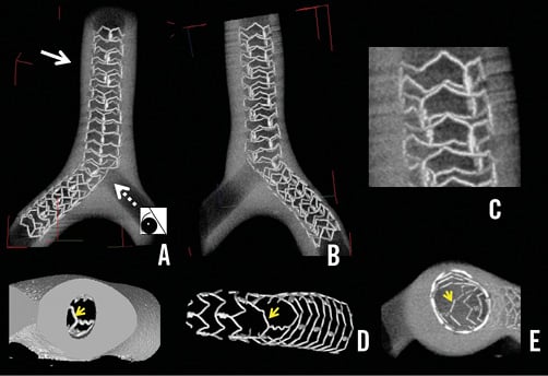
Figure 7. Images of MULTI-LINK ZETA stent with 3-link connection. A) View from the top. B) View from the bottom. C) Magnified view of overdilatation of the proximal struts outlined by the arrows in panels A) and B). D) Magnified view of the LCX ostium, after complete removal of the jailed struts, from the vantage point shown by the dotted arrow in panel A). E) Cross-sectional view from the inner side at the bifurcation. The jailed strut remained on the myocardial side (D, E, arrows).
COMPUTER-BASED MEASUREMENTS OF CORONARY FLOW
PEAK DIASTOLIC FLOW
In Model A (Figure 8A, A), the acceleration of the peak diastolic flow was concentrated in the centre of the vessel. This accelerated flow remained stable in the distal LM coronary artery. Model B was associated with a marked reduction of the flow velocity in the overdilated area. The vascular deformation to a longitudinal ellipse (C) or tilted ellipse (D) also created zones of low flow in the overdilated side. These kinds of overdilatation slowed the peak flow in the distal LM artery without any change in its position in the centre of the vessel (Figure 8).
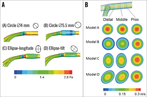
Figure 8. Computer simulations of coronary peak diastolic flow in the LM coronary artery model. A) Whole area analysis. Model A: normal dilatation of the circle with its 4.0 mm diameter in the LM coronary artery. Model B: overdilatation of the circle to a 5.5 mm diameter. Model C: ellipse-longitudinal deformation. Model D: ellipse-tilt deformation. B) Cross-sectional analysis of coronary flow. Note the generation of the low-flow area at the overdilated area in Models B, C, and D.
SYSTOLIC FLOW
The accelerated flow was in the centre of the LM coronary artery as well as the diastolic peak flow. Broad areas of low flow were present in the overdilated segment in Models B, C, and D.
Discussion
In case of SB narrowing after MV stenting, KBI, instead of isolated SB dilatation (which may deform the MV), has been recommended to preserve the SB access16. Advancing the guidewire into the distal strut of the SB orifice is important to cover the SB ostium properly15,16. However, the efficacy of KBI using a single stent remains controversial. Recent clinical trials have reported the ineffectiveness or negative effects of KBI. The Nordic-Baltic III trial found that its advantage was limited to a lower rate of SB restenosis (7.6% vs. 20.0%) in true bifurcation lesions10. In the THUEBIS pilot trial, where the SB intervention was randomly assigned to mandatory versus provisional groups, depending on the SB flow deterioration, the MACE rate was similar in both study groups (17.9% vs. 14.8%) despite a higher performance of KBI (73.2% vs. 13.0%)17. In the COBIS trial, KBI was associated with a higher MACE rate (8.7% vs. 4.7%) than treatment without KBI11. It is noteworthy that the rate of TLR of the MV was higher in the KBI (7.0%) than in the non-KBI (3.1%) group, whereas the rate of TLR in the SB was low (2.0% vs. 0.1%) in both groups11. This suggests that the adverse effects are mainly attributable to the stent deformation or intimal injury in the MV instead of the SB.
The long-term effects of a jailed strut at the SB ostium are unclear. Among SB with >75% angiographic stenosis, only 27% had a fractional flow reserve <75%12. In a computer-simulated rheological analysis, turbulent flow was observed behind the jailed strut18. Opening the jailed strut and relieving the SB stenosis increased the oscillation of shear stress in the bifurcated area19. The concomitant presence of high and low shear wall stress and an increase in its oscillation might activate the platelets and their deposition, and cause thromboembolic complications20. Recent clinical studies using optical coherence tomography revealed that the degree of intimal coverage of the jailed strut depended on the kind of DES21,22 and on the performance of the final KBI22. KBI achieves the removal of the jailed strut and facilitates re-crossing of the guidewire and re-endothelialisation. However, suboptimal KBI with inappropriate guidewire re-crossing, using a stent with three or more links, undersized balloon selection or X-shape balloon overlapping has the possibility of jailed struts remaining15. Further studies are needed to assess the effects of jailed struts on the coronary blood flow, which may be related to the development of restenosis or thrombosis, and whether clearing the SB ostium by KBI brings a clinical benefit in the late phase.
Despite the many clinical studies of bifurcation lesions, few have described the standard KBI procedure. In our study, where KBI was performed at the operator’s discretion, various configurations of the proximal MV stent were observed, which were dependent on the position of the SB balloon chosen by the operator, and on the overlapping style of the two balloons (Figure 2A). The bifurcation angle had an influence on the balloon overlapping despite a similar proximal position in the LBO. In the narrow-angled bifurcation, the two balloons were positioned laterally, whereas the stents overlapped longitudinally according to the degree of the bifurcation angle (Figure 3). In the case treated with LBO, the MFCT study revealed the presence of an oval dilatation in the proximal MV, in contrast to the spherical dilatation observed in the case treated with MBO in a high-angled bifurcation (Figure 4, Figure 5). In the LBO, the deformation of the MV stent increased proportionally to the bifurcation angle, whereas it could be corrected by the MBO with the proximal site dilated by a large, short balloon (Figure 3-Figure 5). The maximal dilatation point could not be predicted because of the deformations caused by the LBO-KBI, whereas, with the MBO-KBI, the proximal edges of the two balloons were located at the same point in the bifurcation (Figure 2, Figure 3, Figure 5). The proximal overdilatation caused by longitudinal or X-shape overlapping incurs a greater risk of edge dissection and secondary restenosis. The various patterns of MV dilation might be an explanation for the different effects of KBI on the MACE rate. Although hugging balloon dilation is still commonly performed to gain more stent area and obtain better apposition in the proximal MV, there would be a possible risk of unpredictable stent deformation. Whatever technique is used, KBI or sequential SB and MV dilatation, the MV optimisation with a larger balloon sized on the proximal MV should be considered as a final step.
In our computer-simulated rheological assessment, proximal overdilatation created a wide, low shear stress area at the sites dilated to an elliptical shape and to symmetrical overdilatation. Therefore, a proximal optimisation technique should be used according to the vascular branching law23-25. A pathological study showed that: A) atherosclerosis developed often on the lateral sides of the bifurcation, where the turbulence of coronary flow was likely to occur with low endothelial shear stress, and B) involvement of the carina was unusual26. The delayed endothelialisation of the carinal area has been reported after DES deployment, where it is exposed to high coronary flow and shear stress26. Stent deployment and its overdilatation in bifurcation lesions may change the local vessel geometry and cause an abnormal flow pattern, which promotes atherosclerosis, thrombus formation, or both. In recent bench testing experiments, the proximal optimisation and balloon dilatation of the SB without KBI created an ideal stent expansion25. However, the risk of compromising the other daughter branch after crossover stenting was higher in the presence of atherosclerotic changes in the carina27. Therefore, balloon dilatation of the SB alone might also compromise the distal MV and, in diseased human coronary arteries, KBI might protect the patency of both daughter vessels.
Several new-generation DES include a 2-link system, while the XIENCE stent (Abbott Vascular) has a 3-link system. The likelihood of complete SB ostial dilatation by KBI is higher with a 2-link than with a 3-link stent system, which incurs a risk of the jailed struts remaining, even after KBI with high pressure. However, from the perspective of stent deformation in the proximal MV, the 3-link stent maintained its structure, whereas the 2-link stent was widely opened and the struts were separated, which might cause a loss of DES efficacy due to injury to the polymer or a decrease in drug concentration. Guérin et al reported that KBI caused an oval-shaped dilation of the stent, and an eccentricity value index of 0.75 and a 30% widening compared to the distal site13. They also found that the metal/artery ratio decreased, as well as the drug delivery/surface ratio at the site of KBI13. This suggests that, in some cases, the greater expansion and easier access are outweighed by a greater injury to the polymer. Further clinical studies of polymer durability and performance of the deformed stent are warranted.
Limitations
Since the present bench studies were performed in a vinyl or silicone tube, the following things are different from the human coronary artery: the elasticity of the vessel, curvature, three-dimensional structure and heart beating. These differences may influence the final stent configuration. Twenty millimetre semi-compliant balloons were used in the KBI to obtain similar compression pressure in both MV and SB. Long length and soft compliance of the balloons may increase the risk of dissection in the clinical setting.
| Impact on daily practice KBI after crossover stenting at the coronary bifurcation lesion incurs a risk of non-uniform and oversized proximal MV dilatation. Minimal balloon overlapping and proximal dilatation of the MV with an optimal size balloon yielded ideal spherical stent dilation, while overexpansion or elliptical deformation by long overlapping KBI may increase the exposure to low shear stress. Although the 2-link stent had the advantage of widely opening the side branch ostium, it incurred a risk of overdilating the proximal strut, whereas the 3-link stent maintained its structure after KBI. |
Conflict of interest statement
The authors have no conflicts of interest to declare.
Online data supplement
Moving image 1. MFCT movie of the stent after MBO-KBI with 60-degree bifurcation angle.
Moving image 2. MFCT movie of the stent after LBO-KBI with 60-degree bifurcation angle.
Moving image 3. Axial view of the stent after MBO-KBI.
Moving image 4. Axial view of the stent after LBO-KBI.
Moving image 5. MFCT movie of Endeavor stent with 2-link connection deployed in a 3-dimensional Y-shaped model.
Moving image 6. MFCT movie of MULTI-LINK ZETA stent with 3-link connection.