Condensation Heat Transfer in Horizontal Non-Circular Microchannels ()
1. Introduction
Understanding the heat transfer behavior of condensation flow in microchannels is important for a broad variety of engineering applications. Although there have been a number of investigations on boiling flow in microchannels, there are relatively little experimental data and theoretical analyses relative to condensation processes available in the literature, especially, for condensation inside a noncircular microchannels. In the chapter 6 of the reference [1], an overview of minichannels and microchannels condensation has been exposed.
Most of the physical and mathematical models that focused on annular condensation heat transfer in circular channel were developed in the previous works. Begg et al. [2] studied annular film condensation in a small circular tube to predict the shape of the liquid-vapor interface along a miniature tube leading to the complete condensation phenomena in small diameter tubes. LouahliaGualous and Asbik [3] conducted a numerical model predicting heat transfer for condensation of pure refrigerant and binary mixture in a mini-tube. Miscevic et al. [4] developed a stationary condensation capillary flow model based on the separate flow approach by taking into account the coupling between a cylindrical interface and a hemispherical interface. Recently, Ribeiro et al. [5] experimentally investigated the thermal-hydraulic performance of microchannel condensers using three different copper metal foams structures with distinct pore densities and porosities (0.893 and 0.947) as enhanced surfaces on the air-side. Their results are compared with the conventional condenser surface. El Achkar et al. [6] investigated the experimental heat transfer in the isolated bubbles zone of a transparent circular cross-section micro condenser. The evolution of vapor quality was experimentally determined by using the image processing. The energy balance was then used to calculate the temperature of the liquid in the isolated bubbles zone, showing that liquid and vapor were not in thermal equilibrium. The sensible heat transfers and latent heat transfers were then compared. However, a fundamental understanding of local mechanisms of heat and mass transfer cannot be accomplished using multichannels because the mass flow rates for each microchannel and condensate flow regime are unknown. Also, condensation heat transfer and pressure drop depend on the corresponding structure of the two phase flow (mist flow, annular flow, bubbly flow, or slug/plug flow) as shown by Odaymet et al. [7]. Three main condensation flows were identified in a small circular tube: the annular flow, the intermittent or elongated bubbles flow, and the spherical bubbles flow by Louahlia-Gualous and Mecheri [8]. Annular flow is especially found to be one of the dominant condensation flows in microchannelsas shown by Odaymet and LouahliaGualous [9] and Quan et al. [10].
On the other hand, various theoretical models have been proposed to predict the local heat transfer related to the condensation annular flow in non-circular channel where the surface tension plays a predominant effect on the condensate flow, more specifically, in the channel corners. Indeed, Zhao and Liao [11] analyzed annular film condensation heat transfer inside vertical mini triangular channel using three zones: the thin liquid film flow on the sidewall, the condensate flow in the corners, and the vapor core flow in the center. Wu and Cheng [12] carried out a simultaneous visualization and measurement experiment to perform condensation flow patterns of steam flowing through an array of trapezoidal silicon microchannels with a hydraulic diameter of 82.8 µm. Wang et al. [13] and Wang & Rose [14] proposed a theoretical model for condensation annular flow in a horizontal square and equilateral triangular channel with hydraulic diameter ranging from 0.5 to 5 mm by taking into account the effects of gravity, surface tension, and interfacial shear stress. They obtained the local heat transfer coefficient for refrigerants R134a, R22, R152a, CO2, propane, ammonia, and R410a by assuming that the channel wall temperature is uniform. Furthermore, they proposed one correlation for condensation heat transfer in the square and triangular microchannels in which surface tension and viscosity are the predominant parameters controlling condensate film thickness. Additionally, in references ([15-18]) for which the contents are not detailed here, readers could find more information about the use of various non-circular microchannel shapes.
The main purpose of the present work is to determine the heat transfer coefficient during the steam condensation inside horizontal various non-circular microchannels (rectangle, square, or equilateral triangle). Indeed, the classical mathematical model of the annular condensation flow is retained in both phases (liquid and vapor). An appropriate numerical method is used to solve the differential equations system obtained from different conservation equations (mass, momentum and energy). To compute the heat transfer coefficient, a new and simple geometrical method is used to express the condensate film thickness.
2. Physical Model
The physical model investigated in this paper is illustrated on the Figure 1. It concerns, a horizontal non circular microchannel with a hydraulic diameter D, which is cooled with a uniform wall heat flux density q. At the microchannel inlet, the vapor (steam) mass flux, the pressure and temperature of the steam is given at the saturated state. The vapor condenses inside the microchan-

Figure 1. Schematic representation of the annular condensation in a rectangular microchannel.
nel having wall temperature lower than vapor saturation temperature. The film thickness on the heat exchange surface varies along the axial direction with the vapor quality.
When total condensation occurs, the end of the condensation zone has a hemispherical meniscus. Its length L is one of the unknown parameters in the physical model. The condensate film flows along the axial direction under effects of the pressure, surface tension, and shear stress.
3. Mathematical Formulation
3.1. Hypotheses
The mathematical formulation of the problem is based on the following principal assumptions:
• For liquid and vapor phases, thermophysical properties are assumed to be constant.
• In the microchannel, the flow is supposed to be steady-state, laminar, one-dimensional and axis-symmetrical.
• The free surface of the condensate film is smooth.
• Gravity forces are negligible compared to the effects of surface tension.
• The heat transfer from the cooling fluid to the condensate flow is assumed to be one-dimensional.
• In the condensate, the temperature profile is supposed linear.
• The saturation temperature of the vapor is assumed to remain constant along the microchannel.
3.2. Conservation Equations
The modeling approach developed here describes the liquid and vapor phases separately. The governing equations are used in the Cartesian coordinates as shown in the Figure 1.
3.2.1. Mass Conservation
The average parameters over a cross-section are used in liquid and vapor phases of the condensation flow respecting continuity conditions at the liquid-vapor interface. The equation of the mass conservation can be written for each local cross section as follows:
 (1)
(1)
 (2)
(2)
where  represents the volumic rate of phase change. By convention, its sign is negative for condensation and positive for evaporation. So, we can write:
 (3)
(3)
 ,
,  and
and  are respectively the microchannel cross section, the density and the axial velocity. The subscript
  refers to the considered phase (
 = v or L).
3.2.2. Momentum Conservation
For a fixed position z along the microchannel, the condensate film thickness in noncircular microchannels is much thicker into the microchannel corners than elsewhere, especially; at the internal considered circumference because of the surface tension effect. This is the reason that the axial flow in the film region between the corners is neglected.
From the forces balance illustrated on the Figure 2, the momentum conservation equations in the control volume of the length dz, are given by the equations (4) and (5). These relationships are essentially expressed in terms ofthe interfacial shear at the liquid-vapor interface, the shear wall friction at the liquid-wall contact surface, and the pressure forces on the liquid area. In both phases, all the physical properties are assumed to be constant, and the influences of the gravity and the buoyancy forces are neglected. So, in the liquid and vapor phases, the momentum conservation equations are:
• In the liquid phase:
 (4)
(4)
• In the vapor phase:
 (5)
(5)
 ,
,  and
and  are respectively the microchannel cross-section, the pressure and the axial velocities in the phase
  . Furthermore, we indicate that
  is the liquid–vapor interface surface along
  ,
,  is the wet heat exchange surface along
  , and
, and  is the shear stress at liquid–vapor interface,
  is the shear stress at the microchannel heat exchange surface.
3.2.3. Energy Conservation
The local energy equation in the liquid phase can written as:
 (6)
(6)
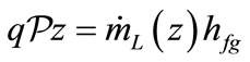
The total energy equation defined in the length of the total condensation zone as:
 (7)
(7)
where q is the heat flux density,  is the local liquid mass flow rate
  is the microchannel perimeter, and z is the microchannel abscissa.
3.2.4. Curvature Radius Expression
To express the curvature radius derivative, we need to use the Laplace–Young equation:
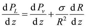 (8)
(8)
Combining equations (1)-(8), we get:
 (9)
(9)
3.2.5. Dimensionless Equations
To establish the dimensionless equations, the following variables are used:
 (10)
(10)
Then the dimensionless form of the derivative curvature radius, the velocity gradients and the pressure gradients in both phases, are given by:
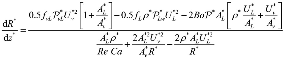 (11)
(11)

Figure 2. Forces balance for two-phase flow in a horizontal microchannel.
 (12)
(12)
 (13)
(13)
 (14)
(14)
 (15)
(15)

are respectively the boiling number, the capillary number, the vapor Reynolds number and the vapor mass flux.
Definitions of other parameters appearing in the above relations (11-15) are such that:
1) The liquid friction factor for laminar is given by:
 (16)
(16)
C is the Poiseuille number given in [19].
For turbulent flow, the liquid friction coefficient is determined from the Blasius equation [1]:
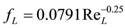 (17)
(17)
In this expression, the liquid Reynolds number  is calculated assuming the liquid single phase:
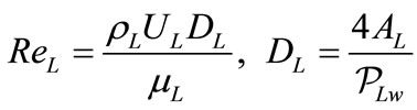 (18)
(18)
2) The interfacial frictional coefficient taking into account the effect of the condensation process on the interfacial shear stress is defined by [20]:
 (19a)
(19a)
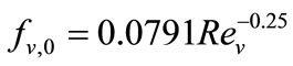
where fv,0 is the friction factor for single phase vapor flow defined for laminar flow as :
 (19b)
(19b)
For turbulent flow,  is determined from:
 (20a)
(20a)
 , (20b)
The factor  is defined as the ratio of the local condensation mass flow rate to the vapor mass flow rate rebounding from the liquid-vapor interface [2], which is approximated by:
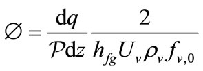 (21)
(21)
3.2.6. Dimensionless Boundary Conditions
Equations (11) to (15) are solved using the following dimensionless boundary conditions:
1) At the microchannel inlet (z* = 0):
• the flow mass flux G is imposed;
• the temperature and pressure at the saturated state are given;
• the non-dimensional vapor velocity is

• the non-dimensional liquid velocity is
 ;
;
• the non-dimensional curvature radius is

2) At the position z* = L* corresponding to the end of the condensation zone:
• the non-dimensional outlet liquid pressure is:
 ;
;
• for the rectangular cross section, the dimensionless curvature radius is [22]:

where  ;
;
• for the equilateral triangle cross section, the dimensionless curvature radius a is [18] :

4. Solution Procedure
The above boundary conditions combined with nondimensional equations (11)-(15) constitute the mathematical model of two-phase flow in capillary regime with a vapor-liquid phase change. Solution of this mathematical model is not trivial since one of the limit positions remains to be found, the value of L being one of the unknowns of the problem. So, the iteration process is used to solve the mathematical model. To start the calculations, the saturated vapor at the inlet of the tube is assumed having the known mass flux, temperature, pressure, and vapor quality. For the next axial step  , the following steps are executed:
1) To start calculation, an arbitrary total condensation length is assumed;
2) Calculation of the curvature radius from equation (11);
3) Calculation of the local liquid velocity from equation (12);
4) Calculation of the local vapor velocity from equation (13);
5) Calculation of the liquid pressure from equation (14);
6) Calculation of the local vapor pressure from equation (15);
7) Calculation of the total condensation length from equation (26).
Steps 2) to 7) are repeated until the value of the condensation length obtained at the iteration number “it” is approximately equal to the one determined at iteration number “it-1”.
Knowing the total condensation length, calculations are then made for the next values of z locations. For each z location, steps 2) to 7) are made and calculation is stopped when z value is approximately equal to the total condensation length L.
5. Computation of the Heat Transfer Coefficient and the Condensation Length
5.1. Calculation of the Heat Transfer Coefficient
Assuming that the temperature profile is linear in the condensate film, the local heat transfer is expressed by:
 (22a)
(22a)
and hence the average heat transfer coefficient in the microchannel condensation length L is performed by the relationship:
 (22b)
(22b)
Two last quantities are used to determine the average and the local Nusselt numbers respectively:
 (23a)
(23a)
 (23b)
(23b)
 is the average condensate film thickness for each z location along the microchannel. Using the geometrical considerations from the Figure 3, the following analytical expression is established:
 (24)
(24)
5.2. Calculation of the Condensate Length
The parameter dR/dz given by the equation (9) is expressed in terms of the limit curvature radius  .
.
At z = L location, dR/dz is to be infinite which causes a calculation problem. To avoid this complication, we set  where
where  is an infinitesimal parameter. The limit values of the curvature radius and its first derivative are defined as [22]:
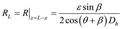 (25)
(25)
 (26)
(26)
To estimate the numerical value of the condensation length a dichotomy method was performed using equation (26), between the inlet of the microchannels which corresponds to  and the end of the condensation zone where
6. Results and Discussions
6.1. Numerical Results Validation
The validation of the results obtained in the present work for condensation of water in a square microchannel, are compared to the predictions of various correlations available in the literature. These correlations are proposed for condensation heat transfer in microchannels and macrochannels. Among these predictive correlations, those of condensation in microchannels are defined by Wang et al. [26], Koyama et al. [23], and Wang & Rose [14]. Figure 4 shows the comparisons between the average Nusselt number obtained from the present numerical model and those predicted by seven correlations: Dobson et al. [22], Wang et al. [26], Koyama et al. [23], Wang & Rose [14], Traviss et al. [24], Shah [19], and Ackers et al. [25]. Results presented in the Figure 4 are those obtained for condensation of steam in a horizontal square microchannel with hydraulic diameter of 110 µm, for various inlet-

Figure 3. Distribution of the condensate film in the microchannel corners.

Figure 4. Comparison of the present work with predictions of literature correlations.
vapor mass fluxes ranging from 70 to 220 kg/m²s. It is found that the best predictions of the present average Nusselt number are obtained by the correlations of Dobson et al. [22] and Koyama et al. [23] for which the mean relative deviation is about 7%. Both of these correlations are developed in the case of an annular condensation heat transfer of several pure refrigerants which is carried out in the channels with small hydraulic diameter. The correlations of Traviss et al. [24] and Ackers et al. [25] devoted to the convective condensation heat transfer in the macro-scale channels have been also evaluated to the micro-scale. It can be seen that the correlation of Traviss et al. [24] over predicts highly the present results for low mass fluxes whereas the Ackers’s correlation [25] under predicts them highly for all the range of the tested mass fluxes. Adding up, the correlation of Shah [19] is proposed for condensation heat transfer in channels with large hydraulic diameter from 7 to 40 mm and Wang et al. [26] correlation is defined for condensation heat transfer inside a horizontal small rectangular channel with hydraulic diameter of 1.46mm. Average Nusselt numbers obtained by both of these correlations give the same trend and the reasonable results compared to those predicted numerically. The Shah’s correlation under predicts numerical results with a maximum average deviation of about 16%. As for the correlation of Wang et al. [26], it over predicts the present results with a maximum deviation of 22% obtained at low mass fluxes. Moreover, correlation of Wang & Rose [14] based on the Nusselt theory including the effects of interfacial shear stress and surface tension on condensation heat transfer is also evaluated. Predictions of Nusselt number from the correlation of Wang & Rose [14] are not in accordance with those of this study since they gave the highest deviation of 37% form the numerical results.
6.2. Peripheral Condensate Film Thickness and Local Heat Transfer
Numerical results are given in the Figures 5(a) and (b) and the Figures 6(a) and (b) for steam condensation in square section microchannel with hydraulic diameter of 110 and 250 µm. Computations were conducted for vapor mass flux G = 90 kg/m²s, contact angle q = 15˚, heat flux density q = 100 kW/m². For the conditions used in the present computation, the boiling number, the capillary number, the inlet steam temperature and pressure are maintained constant.


Figure 5. Evolution of the condensate film thickness around the square microchannel circumference.


Figure 6. Evolution of the local Nusselt number around the square microchannel circumference.
To better understand the behavior of the peripheral local heat transfer coefficient, Figures 5(a) and (b) show predicted square channel condensate film thickness (24) plotted as a function of the peripheral coordinate W at four different axial locations. It can be seen from these figures that for the same z location on the microchannel, the condensate film thickness is higher for 250 µm (Figure 5(b)) than for 110 µm (Figure 5(a)). According to these representations, it is observed that for both microchannels, the symmetrical distributions of the condensate film thickness are obtained around the channel perimeter because the gravity has no effect on the condensate flow in microchannel. The condensate film thickness is very thick in the microchannel corners (W = 45˚, 135˚, 225˚ and 315˚) under the effect of the surface tension whereas it becomes very thin at W = 0˚, 90˚, 180˚ and 360 where the heat transfer is the highest. These trends have been reversed for the peripheral local heat transfer coefficient (see Figures 6(a) and (b)) even if the symmetrical distributions are conserved.
6.3. Influence of the Cross-Section Shape on the Heat Transfer Coefficient
To indicate the influence of the channel cross-section shape, we start by the presentation of the results concerning curvature radius. In fact, Figure 7 shows the variation of the dimensionless curvature radius along the flow direction in three cross-section shapes of microchannels. At the beginning and the end of the condensation, the curvature radius increases rapidly along the channel, while it increases slowly at the middle. We also note that for the triangular microchannel it’s increasing very quickly than other geometries. The present simulation results are similar to those of the reference [21].
The annular condensation length is one of the most important parameter which influences the thermal performance of the microchannel studied here. Figure 8 gives the dimensionless annular condensation length with respect to the boiling number Bo, for three cross-section shapes. As shown in this figure, the condensation zone decreases with Bo and it is also clear that the cross-section shape of the microchannel plays a noticeable role on the condensation.
In the heat transfer exchange point of view, the influence of the microchannel shape on the average Nusselt number is highlighted by studying condensation of steam in a square, equilateral triangular, and rectangular microchannels with the same hydraulic diameter of 250 µm. The sides of the equilateral triangular and square microchannels are 433 µm and 250 µm respectively. For rectangular microchannels having the same hydraulic diameter, the aspect ratio is about 2, 3 and 4. Three different rectangular cross sections are investigated: 375 × 187.5 µm², 500 × 166.6 µm² and 625 × 156.25 µm².
Under the same conditions, Figure 9 compares the average Nusselt numbers with respect to the vapor Reynolds number for five microchannel cross-sections. According to this figure, it is seen that annular condensation Nusselt number is low for square microchannel cross section (aspect ratio of 1). For rectangular cross-section microchannels with aspect ratio (b/a) higher than 1, condensation Nusselt number increases by increasing aspect ratio. The highest Nusselt numbers values are obtained

Figure 7. Dimensionless curvature radius along various microchannel shapes.

Figure 8. Dimensionless condensation length versus the boiling number.
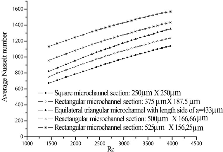
Figure 9. Comparison of the average Nusselt number for various microchannel shapes with the same hydraulic diameter (D = 250µm).
for microchannel with high aspect ratio (equal to 4) and low confinement (a = 156.25 µm). It is interesting to note that for the same hydraulic diameter, the microchannels perimeter and cross section increase with the aspect ratio leading to a reduction of the condensate film thickness. This is due to the predominant effect of the surface tension in the microchannel that increases with microchannel perimeter and thins the condensate film along the sides of the microchannel. For the same Reynolds number, average Nusselt number for equilateral triangular microchannel is between Nusselt number for rectangular microchannel with aspect ratio of 2 and that with aspect ratio of 3. Recall that the perimeter of the triangular microchannel is about 1299 µm and those of rectangular microchannels with aspect ratios of 2 and 3 are about 1125 µm and 1333 µm respectively.
7. Conclusion
The numerical model characterizing local heat and mass transfer for condensation in microchannels has been developed by including the effects of wall and liquid vapor interface shear stresses, surface tension, pressure forces, contact angle, etc. Numerical results are compared for steam condensation in square, rectangular, and equilateral triangular microchannels with the same hydraulic diameter. They are compared with the correlations available in the literature and it is shown that correlations for annular condensation in macro-channels predict heat transfer with significant deviations from those obtained for microchannels. The best predictions are obtained with the correlations of Dobson et al. [25] and Koyama et al. [24].
By using the established condensate film thickness expression [24], the influence of the microchannel hydraulic diameter is highlighted. Indeed, increasing this last geometrical factor increases the peripheral condensate film thickness and hence decreases the peripheral condensation heat transfer coefficient. Additionally, we point out that at the beginning and at the end of the condensation, the curvature radius increases rapidly along the channel, while it increases slowly at the middle. We also note that for the triangular microchannel it’s increasing quicker than other geometries. As for the annular condensation length, we note that it decreases with increasing of the boiling number and its numerical values diminish in the case of equilateral triangular microchannel.
Finally, to show the major influence of cross-section shape on the condensation heat transfer, comparison of the average Nusselt number is conducted for different microchannel shapes with the same hydraulic diameter. It can be concluded that condensation average heat transfer increases with aspect ratio for rectangular microchannels. The lowest average Nusselt numbers are obtained for the square microchannel because its perimeter and cross section are lower than those of triangular and rectangular microchannels.
Nomenclature
List of Latin symbols A: Area (m²)
a: Width of rectangular microchannels (m)
b: Depth of rectangular microchannels (m)
c = 1/4, 1/3: Inverse relationship of number of corners
D: Hydraulic diameter (m)
f: Friction factor hfg: Latent heat (J∙kg−1)
l: Annular condensation length (m)
l: Length of the end part in condensation (m)
M: Mass flux (kg∙s−1)
P: Pressure (Pa)
Q: Heat flux density (W∙m−2)
R: Curvature radius (m)
 : Perimeter (m)
U: Velocity (m∙s−1)
Greek symbols
Β: Half of right angle (˚)
ε = min(a,b) (m)
μ: Viscosity (kg m−1s−1)
θ: Contact angle (˚)
ρ: Density (kg∙m−3)
σ: Surface tension coefficient (N∙m−1)
τ: Shear stress (N∙m−2)
Ω: Peripheral angle (˚)
Subscripts
L: Liquid
Lw: Liquid-wall interface
V: Vapor
Vl: Liquid-vapor interface
O: Inlet