


Abstract
We present the detection of 661 known pulsars observed with the Australian SKA Pathfinder (ASKAP) telescope at 888 MHz as part of the Rapid ASKAP Continuum Survey (RACS). Detections were made through astrometric coincidence and we estimate the false alarm rate of our sample to be ∼0.5%. Using archival data at 400 and 1400 MHz, we estimate the power-law spectral indices for the pulsars in our sample and find that the mean spectral index is −1.78 ± 0.6. However, we also find that a single power law is inadequate for modeling all the observed spectra. With the addition of flux densities between 150 MHz and 3 GHz from various imaging surveys, we find that up to 40% of our sample show deviations from a simple power-law model. Using Stokes V measurements from the RACS data, we measured the circular polarization fraction for 9% of our sample and find that the mean polarization fraction is ∼10% (consistent between detections and upper limits). Using the dispersion-measure-derived distance, we estimate the pseudo-luminosity of the pulsars and do not find any strong evidence for a correlation with the pulsars' intrinsic properties.
Export citation and abstract BibTeX RIS

Original content from this work may be used under the terms of the Creative Commons Attribution 4.0 licence. Any further distribution of this work must maintain attribution to the author(s) and the title of the work, journal citation and DOI.
1. Introduction
Because of the complexity involved in modeling a pulsar's magnetosphere, a complete theory of pulsar emission that explains the diverse observed emission properties remains to be understood (Goldreich & Julian 1969; Sturrock 1971; Ruderman & Sutherland 1975; Krause-Polstorff & Michel 1985; Taylor & Stinebring 1986; Cerutti & Beloborodov 2017). Observational evidence in this regard provides a very useful avenue for phenomenologically understanding the underlying emission processes (e.g., Radhakrishnan & Cooke 1969).
The spectral and polarimetric signatures of the observed emission are two of the most common properties that can be measured in a large number of pulsars, and hence they can provide clues about the pulsar's emission mechanism. The observed spectrum in pulsars is usually characterized by a steep power law, Sν = S0 να , typically with power-law index α < − 1 (Bates et al. 2013). In addition, pulsars are one of the small number of object classes in which the emission can be highly polarized, both linearly and circularly (Lorimer & Kramer 2004). Combing the spectral and polarimetric properties of the pulsars can hence provide an alternative to the routine periodic searches that are used to discover pulsars—through imaging techniques that are independent of the pulsed emission (e.g., Backer et al. 1982; Navarro et al. 1995; Crawford et al. 2000; Dai et al. 2018; Kaplan et al. 2019; Wang et al. 2022a).
Traditionally, most pulsars are discovered through periodicity-searching techniques, where the signal is dedispersed and then searched for periodicities. Later follow-up observations then add up the emission from individual pulses in phase. Average properties like flux densities can be difficult to measure reliably from such observations, as they rely on accurate knowledge of the telescope gain, sky background temperature, pulse duty cycle, and more (Lorimer & Kramer 2004). In contrast, continuum emission from interferometric images provides a useful alternative to discovering and characterizing pulsars. Navarro et al. (1995) used imaging techniques to find a steep-spectrum, highly polarized source, which revealed a 2.3 ms pulsar, PSR J0218+4232, in follow-up periodic searches, in which a significant amount of radio energy was not pulsed. Similarly, Wang et al. (2022a) discovered a circularly polarized transient, which revealed a ∼322 ms pulsar, PSR J0523−7125, in the Large Magellanic Cloud (LMC). Follow-up observations showed it was brighter than all previously discovered pulsars in the LMC, but it might have been missed in the blind periodic searches because of its large pulse width and steep spectrum.
With the advent of all-sky radio imaging surveys, studies searching for pulsars through imaging are rediscovering an increasing number of pulsars (and in some cases serendipitously discovering new pulsars; e.g., Navarro et al. 1995; Kaplan et al. 1998; Han & Tian 1999; Kouwenhoven 2000; Frail et al. 2016; Bhakta et al. 2017; Wang et al. 2022a). In addition, imaging surveys can be extremely fruitful in identifying transients that show unusual polarization properties and/or variability (Kaplan et al. 2019; Wang et al. 2022b), and hence studying the spectral and polarimetric properties of these transients can be used to identify/discover pulsars that show variability through scintillation (Crawford et al. 2000; Dai et al. 2016, 2017). Finally, imaging surveys can measure properties like flux densities reliably for many objects (e.g., Bell et al. 2016; Murphy et al. 2017), characterizing spectral properties and variability.
Although the observed spectrum is usually modeled by a power law, the exact value of the power-law index α is not very well determined; using a sample of 280 pulsars observed at 408, 606, 925, 1408, and 1606 MHz, Lorimer et al. (1995) found α = −1.6 ± 0.3. Analyzing the same data set, but extended to include higher and lower frequencies, Maron et al. (2000) found α = −1.8 ± 0.2. Bates et al. (2013) tried to remove the observational biases to predict the intrinsic pulsar spectrum and found α = −1.4 ± 1.0. With a sample of 441 pulsars observed at 728, 1382, and 3100 MHz, Jankowski et al. (2018) find α = −1.6 ± 0.54. All of the flux density measurements from the above studies were derived using single-dish observations. Moreover, there are cases where a simple power law is not adequate for completely describing the spectrum; most common are the low- and high-frequency deviations of the spectrum (Maron et al. 2000 estimate that, at most, ∼10% of their sample show a preference for more complex models). Using flux densities derived through imaging surveys for 60 pulsars and combing archival data, Murphy et al. (2017) found that a single power law was inadequate for fitting the observed variation in as much as 50% of their sample, with a broken power law providing a better fit, although their data, taken at ∼200 MHz, are more sensitive to pulsars at lower flux densities and hence more sensitive to low-frequency variations. However, none of the above studies find any obvious subpopulation that prefers a broken-power-law fit. In addition to this is the question of whether the spectral index is consistent between the normal and "recycled" pulsars—Kramer et al. (1998) found no evidence for such a disparity between the populations, with the spectral index being consistent. However, Frail et al. (2016) found that the spectra of millisecond pulsars (MSPs) are steeper than normal pulsars, although they attribute this to their survey's selective preference of being sensitive to pulsars at a lower frequency (150 MHz).
Similarly, the studies done so far on polarimetric measurements measure both linear and circular polarizations. An initial study done by Gould & Lyne (1998) finds that the linear polarization is ∼20%–40% and the circular polarization is ∼8%, but with a high degree of scatter, with individual pulsars capable of showing 100% linear polarization. Using a sample of 24 MSPs observed at 730, 1400, and 3100 MHz, Dai et al. (2015) found that the level of circular polarization is ∼8%–10% across the three frequencies. Similarly Johnston & Kerr (2018) used a sample of 600 pulsars observed at 1.4 GHz to find a mean circular polarization ∼9%. Using a sample of 40 normal pulsars, Sobey et al. (2021) found that the circular polarization changes between ∼960 and 3820 MHz roughly by 4%, with a mean polarization of ∼16% and a more recent study (Oswald et al. 2023) finds a consistent circular polarization fraction of ∼5%, consistent with the literature. Xilouris et al. (1998) found that the evolution of the polarization fraction with frequency is more complex in MSPs than normal pulsars, which makes it interesting to study the frequency dependence of the polarization fraction.
In this paper, we present the results of a search for detected radio pulsars using the Australian SKA Pathfinder (ASKAP) telescope (Hotan et al. 2021), an interferometric array of 36 dish antennas, each 12 m in diameter, achieving a resolution of 15''. We make use of the total intensity (Stokes I) and circular polarization (Stokes V) sky maps and source catalogs to detect and characterize the radio emission from pulsars. This paper is organized as follows: Section 2 describes the data reduction and the pulsar sample selection methodology. In Section 3, we present the source properties—the astrometric, spectral characterization, and polarization measurements—of the pulsars in our sample. In Section 4, we provide the implications of our results, combining them with the findings of past studies, before concluding in Section 5.
2. Data Analysis
2.1. Data Reduction
Data were collected as a part of the Rapid ASKAP Continuum Survey (RACS; McConnell et al. 2020), an all-sky survey (south of decl. +51°) initially observing at 888 MHz, with a bandwidth of 288 MHz. The observations were carried out from 2019 April 21 through 2020 June 21 (constituting the first RACS data set; RACS DR1; McConnell et al. 2020) and cover the sky south of +41° decl., with an integration time of 15 minutes, and they were used to generate both Stokes I and Stokes V images. Data were processed using the ASKAPsoft package (Guzman et al. 2019), which includes methods for flagging, calibration, and generating images for each primary beam. The beams were then linearly mosaicked to generate a single image for individual tiles. Flux density calibrations were done using PKS B1934–638, which is the primary reference source used for ASKAP (Hotan et al. 2021). A more detailed description of the reduction techniques used for RACS data can be found in McConnell et al. (2020).
2.2. Sample Selection
We selected all the pulsars from the ATNF catalog (Manchester et al. 2005, v1.69) that are in the RACS DR1 footprint (decl. <41°). At the time of writing, this constituted a sample of 3122 pulsars. In order to avoid source confusion, we removed all the pulsars that are known to be associated with globular clusters, resulting in 2915 pulsars. Sources with astrometric positional errors larger than 10'' were removed to avoid association with background sources in RACS purely by chance, ending up with a sample of 2235 pulsars (∼71% of the original sample). Pulsars can have significant proper motion and hence can result in positional mismatches if this is not accounted for (e.g., J1856+0912, the pulsar with the highest proper motion in our sample, 331.2 mas yr−1, can have an apparent motion of ∼4 2 between the reference epoch and the RACS epoch). Hence, we corrected for the proper motions of the pulsars whenever available, to estimate the pulsars' positions at the RACS epoch. We determined the search radius around an RACS source such that the probability of finding a source with a positional offset r due to the uncertainty σRACS was greater than the probability of finding the closest neighboring source at the same offset, given the local background density
8
ρRACS of the RACS survey. As described by McConnell et al. (2020), there can be systematic uncertainty of ∼2'' for sources in the RACS survey, and hence we choose a conservative error of 2'' on all of the RACS sources. For RACS DR1, we find this search radius to be ∼10''.
2 between the reference epoch and the RACS epoch). Hence, we corrected for the proper motions of the pulsars whenever available, to estimate the pulsars' positions at the RACS epoch. We determined the search radius around an RACS source such that the probability of finding a source with a positional offset r due to the uncertainty σRACS was greater than the probability of finding the closest neighboring source at the same offset, given the local background density
8
ρRACS of the RACS survey. As described by McConnell et al. (2020), there can be systematic uncertainty of ∼2'' for sources in the RACS survey, and hence we choose a conservative error of 2'' on all of the RACS sources. For RACS DR1, we find this search radius to be ∼10''.
We selected all the RACS sources whose positions are consistent with the pulsar's position to within 10'', taking into account the uncertainties in both the RACS and the pulsar's astrometric measurements. This resulted in 661 matches: 600 sources with only a Stokes I match and 61 sources with both Stokes I and Stokes V matches. We visually inspected all 661 matches manually to look for source confusion in the presence of multiple close-by sources, but all of the sources seemed reasonable detections. 9 Taking the local density around these sources, we estimate that for a 10'' search radius, there can be at most four false positives in Stokes I matches and ≪1 in Stokes V matches, with 95% confidence that they could have been identified by chance, and hence the false alarm rate for our sample is ∼0.5%.
3. Results
3.1. Source Properties
The distribution of the sky positions of all the pulsar crossmatches in the RACS data is shown in Figure 1 (sample detection images are shown in Appendix A). All the pulsars from the ATNF catalog are shown in gray dots, while the Stokes I detections are shown in orange diamonds and simultaneous Stokes I and Stokes V detections are shown as blue stars. We see that most of the detections lie along the Galactic plane (shown by the green stripe), tracing the Galactic pulsar population. Spatial offsets were calculated between the positions of the RACS detections and the ATNF catalog positions, and the resulting distribution is shown in Figure 2. We find that ∼98% of the Stokes I detections and 100% of the Stokes V detections are within 5'' of the pulsar's position, suggesting that most of the candidates are likely the pulsar crossmatches as opposed to the random uniform distribution expected for background noise. We find that the median separation between the RACS source and the ATNF position for Stokes I detections is 13 ± 11 and for Stokes V detections it is 15 ± 10 (consistent to within 1σ of each other).
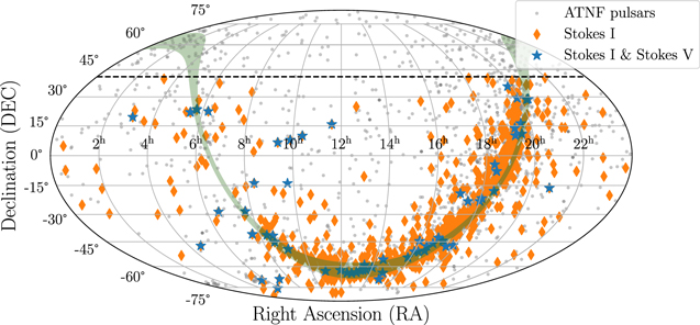
Figure 1. The spatial distribution of all the RACS sources that have an ATNF pulsar within 10''. The sky positions (in Mollweide projection) of all the ATNF pulsars are shown as gray dots, the RACS Stokes I pulsar detections are shown as orange diamonds, and the simultaneous RACS Stokes I and Stokes V detections are shown as blue stars. The black dashed line shows the decl. limit, +41°, for RACS DR1. The Galactic plane within ∣b∣ < 5° is shown by the green shaded region.
Download figure:
Standard image High-resolution image
Figure 2. Distribution of the spatial offset between the ATNF catalog positions and the RACS positions for the pulsar crossmatches. The blue histogram shows the distribution for the RACS Stokes I crossmatches and the black histogram shows the same for the RACS Stokes V sources.
Download figure:
Standard image High-resolution image3.2. Completeness
The distribution of the pulsars detected in the RACS survey as a function of their flux density is shown in Figure 3. We see that most of the pulsars in the sample have flux densities of a few millijansky (toward the detection limit), with a handful of them detected at very high flux densities (>jansky). The red histogram shows the observed number of sources per flux density bin, and the black error bars show the asymmetric 1σ upper and lower limits (calculated according to Gehrels 1986). For a uniform spatial distribution of standard candles, the number of observable sources with flux density >Sν
follows a simple power law,  , where β is the power-law index. For a two-dimensional distribution of sources in the Galactic plane (pulsars have a typical scale height of ∼300–350 pc, which is much smaller than their distances ∼2–6 kpc; Mdzinarishvili & Melikidze 2004; Lorimer et al. 2006), β = −1 and hence we fit the observed number of pulsars with a power law of slope −1. Below a certain flux density limit, we will see a drop-off from the expected distribution, which can be used to assess the (in)completeness of the survey. The black dashed line in Figure 3 shows the best fit for the number density of sources assuming β = −1.

Figure 3. The distribution of the number of pulsars as a function of flux density detected in the Stokes I images (left) vs. the Stokes V images (right) is shown by the red histogram. Shown by the dashed black line is a power-law fit to the number of sources per flux density bin, assuming a two-dimensional (Galactic) distribution of standard candles (β = −1). The vertical black dashed–dotted line shows the flux density limit below which we see large deviations in the observed number of sources, suggesting that the survey is complete above ≈2 mJy.
Download figure:
Standard image High-resolution imageWe can see that for Stokes I (left), there seems to be a turnover at ∼2 mJy (marked by the black dashed–dotted line), below which we see a rapid drop in the number of detected sources, suggesting that the survey is complete above a flux density level of ∼2 mJy. A similar analysis for the Stokes V sources is difficult, due to the small number of sources per bin, but the completeness limit estimated for the Stokes I matches seems to be consistent with the Stokes V population. This is higher than the expectations based on the noise in the RACS images, roughly 0.25 mJy beam−1 at high latitudes, leading to a 1.25 mJy limit at 5σ, but reasonable when the locations of the pulsars in the Galactic plane (with higher confusion noise) are considered.
We then compared the astrometric and spin properties of the pulsars detected in RACS with the overall population of pulsars from the ATNF catalog using a nonparametric test, the Anderson–Darling (AD) test (Anderson & Darling 1952; Scholz & Stephens 1987). Figure 4 shows a comparison of the Galactic latitudes of the detected population with the overall population of pulsars. We observe a deficit in the number of pulsars detected for the pulsars that lie close to the Galactic plane (∣b∣ < 8°). The AD test yields a p-value of 0.004, which provides evidence against the null hypothesis that the population recovered from our survey and the population from the periodic searches are similar. This can be expected, because the background noise is higher for sources closer to the Galactic plane, reducing the number of detections. To test this, we estimated the number of pulsars that would be detected if the flux density limit for the detection were higher (3 mJy). This would remove all the fainter sources that were detected at higher latitudes because of the lower background noise compared to the ones in the plane. The orange histogram in Figure 4 shows this expected number, and we see that it traces the overall observed population from the periodic searches (a p-value of 0.25 for the AD test). We conclude that the low-latitude deficit that we observe in our data is attributable to the increased background noise in the Galactic plane, which causes the sources with lower flux densities to be preferentially detected at higher latitudes. We repeated a similar exercise for the spin period distributions, but we did not find any evidence against the null hypothesis, so we concluded that the detection of sources in imaging surveys like ASKAP is not dependent on the spin period (as expected).
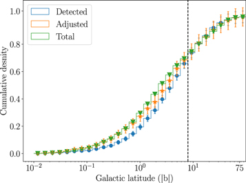
Figure 4. The distribution of the Galactic latitudes of the pulsars detected in our sample. The blue histogram shows the Galactic latitudes of the pulsars detected in the RACS survey, and the green histogram shows the overall distribution of the pulsars from the ATNF catalog. We see that there is a deficit in the number of pulsars detected for ∣b∣ < 8° (the vertical dashed line). We then remove all the detected pulsars below 3 mJy, and the resulting distribution (orange histogram) traces the expected population.
Download figure:
Standard image High-resolution image3.3. Flux Density Uncertainties Due to Scintillation
In addition to the statistical uncertainties in the flux densities due to measurement noise, there can be additional uncertainties in the flux density due to diffractive scintillation. Inhomogeneities in the ionized interstellar medium (ISM) cause random perturbations in the phases of the radio signals, which can interfere to produce a scintillation pattern at the receiver. Hence the observed flux density can be strongly modulated if the scintillation is extreme. The strength of scintillation (characterized by the number of brightness maxima in the time–frequency plane, known as "scintles") can be described by the diffractive scintillation bandwidth (Δνd ) and the diffractive scintillation timescale (Δtd ; see Cordes & Lazio 1991 for a review). The number of scintles in the frequency and time domains are given by

where Δν and Δt are the observing bandwidth and the observational duration (for RACS observations, these are 288 MHz and ∼1000 s, respectively) and η ∼ 0.1–0.2 (we considered η = 0.15). For diffractive scintillation, the fractional error in the flux density is  .
.
Figure 5 shows the fractional error in the flux density that can be caused due to diffractive scintillation as a function of the dispersion measure (DM) for all the RACS sources in our sample. We see that most of the pulsars in our sample are in the regime where the errors due to diffractive scintillation are not very significant (fractional error <0.5), but there are a few pulsars (∼2.5% of the entire sample) that have a fractional error of >0.5. This limit on the fractional error can be roughly translated to a limit on the DM—most of the pulsars with fractional error >0.5 have DM < 10 pc cm−3 and those with fractional error >0.1 have DM < 40 pc cm−3.
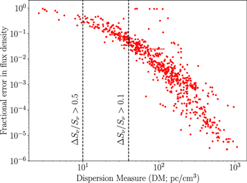
Figure 5. For pulsars identified in the RACS data, the fractional error in flux density due to diffractive scintillation as a function of the DM is shown as the red dots. We see that only a few pulsars (18 pulsars in the sample—∼2.5% of the sample) are strongly affected (having a fractional error >0.5) by scintillation, and most of them have DM < 10 pc/cm3. We can also see that most of the pulsars that have a fractional error of >0.1 have DM < 40 pc/cm3.
Download figure:
Standard image High-resolution imageIn addition to diffractive scintillation, pulsars are also known to suffer long-term intensity variations caused by the large-scale structures in the ISM, due to refractive interstellar scintillation (RISS; Sieber 1982). This can cause the flux density to vary over days to months, which can be a limiting factor when modeling the pulsar spectra using nonsimultaneous flux density measurements (see Section 3.4). Following Romani et al. (1986) and Bhat et al. (1999), we estimate the fractional error in the flux density due to RISS for the pulsars in our sample. We use the Cordes & Lazio (2002) electron density map to estimate the distance to the pulsar and the scattering measure (see Kaplan et al. 1998; Bhat et al. 1999). We find that for most of the pulsars in our sample, the fractional error varies from 6% to 18% (the 16th and 84th percentiles).
3.4. Spectral Index Distribution
From the sample of 661 pulsars that had an RACS counterpart within 10'', 168 pulsars had measured flux densities at 400 and 1400 MHz 10 (ATNF catalog). Table B1 gives the flux density measurements for the 168-pulsar sample. We performed a least-squares fit to find the spectral index, assuming a power-law distribution, using the flux densities at 400 MHz (ATNF catalog), 888 MHz (RACS low DR1), and 1400 MHz (ATNF catalog). From a visual examination, we excluded 18 pulsars where the flux densities cannot be modeled by a single power law, since they show nonmonotonic behavior, either from more complex spectral behavior (Bates et al. 2013; Swainston et al. 2022) or from variability among nonsimultaneous measurements. Figure 6 shows the 18 pulsars in our sample that show nonmonotonic spectral evolution and hence cannot be described by a power law. For the rest of the sample, we find that not all the pulsars can be adequately modeled by a power-law spectrum; of the 150 pulsars that show monotonic spectral variation, only 90 pulsars (60% of the sample) can be well modeled by a power law (they have a goodness of fit with reduced χ2 ≤2).

Figure 6. The sample of 18 pulsars that deviate significantly from monotonic spectral energy distributions. Each line in the plot shows the spectrum for a single pulsar using the flux density measurements taken at 400, 888, and 1400 MHz. The color scheme represents the extent of the deviation from a flat spectrum (violet/yellow corresponds to maximum deficit/excess) added over the three frequencies. The flux density at 888 MHz is normalized to 1. We excluded such pulsars from the fit when using a simple power law to model the spectrum.
Download figure:
Standard image High-resolution imageFigure 7 shows the ratio of the observed to the power-law-modeled flux densities (or the difference between the observed and the power-law-modeled flux densities in logarithmic space) for our sample of 150 pulsars. If a power law accurately models the observed spectral variation, then this ratio has to be consistent with unity within measurement uncertainties and any variation in addition to this reflects the inability of a single power law to model the source spectrum. We find that in ∼40% of the pulsars, the source spectrum cannot be well modeled by a simple power law, with low- and high-frequency deviations seen commonly in this subset of pulsars.
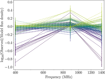
Figure 7. The residual (observed−predicted in logarithmic space) or the ratio between the observed flux density and the power-law-modeled flux density for the 150 pulsars that exhibit monotonic trends. The individual colored dashed lines show the residuals for each pulsar in our 150-pulsar sample. The color scheme represents the degree of error summed over the three frequencies resulting from a power-law fit, with violet and yellow representing maximal overprediction and underprediction, respectively, by a power-law spectrum. It can be clearly seen that for many pulsars, a simple power-law fit is not adequate where the lower- and higher-frequency deviations are very commonly seen.
Download figure:
Standard image High-resolution imageThe residuals at the three different frequencies are shown in Figure 8. All the residuals are scaled with the flux density uncertainties to see the deviation from white noise. As can be seen, in many cases, the residuals are much larger than the usual 1σ limit (the median values of the residuals are ∼1.8σ, 1.3σ, and 2σ at 400, 888, and 1400 MHz, respectively, overpredicting/underpredicting the flux at 400 and 1400 MHz in many cases.
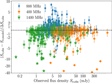
Figure 8. Residuals between the observed flux densities and the power-law-modeled flux densities at all three different frequencies—400, 888, and 1400 MHz, shown by orange, blue, and green error bars, respectively. The residuals are normalized by the uncertainty in the flux density measurements at the three different frequencies.
Download figure:
Standard image High-resolution imageWe note, though, that these measurements are not simultaneous, so temporal variations could appear as spectral variations. Aside from significant intrinsic variability, which is present in some pulsars (e.g., Kramer et al. 2006), RISS can also cause long-term intensity variations. However, as shown in Section 3.3, we expect this to be ∼6%–18% for most of the pulsars. There may be a few cases where the fluctuations due to RISS may be comparable to the deviations from a simple power law, but the prevalence of pulsars in which we see deviations from a simple power law and large residuals from a power-law fit means that RISS alone cannot be responsible. This echoes previous conclusions that a power law is not always a good description of the pulsar spectrum and highlights the low- and high-frequency turnovers that are commonly seen (Maron et al. 2000; Lorimer & Kramer 2004; Murphy et al. 2017; Swainston et al. 2022).
Figure 9 shows the distribution of spectral indices in this sample of 150 pulsars. We find that using two of the three frequencies (the two lower or two higher frequencies) for the fit results in different distributions. This can be explained if the source spectrum deviates from the power law in the presence of low-/high-frequency deviations. In the presence of low-/high-frequency deviations, using the two lower or two higher frequencies can result in shallower and steeper fits compared to the actual spectrum, leading to the deviation between these histograms in Figure 9. We find that the mean spectral index is −1.78 ± 0.6, which is toward the steeper end, but still consistent with existing literature (e.g., Lorimer et al. 1995; Bates et al. 2013; Jankowski et al. 2018).
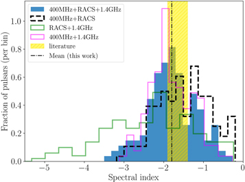
Figure 9. Distribution of spectral indices using the sample of pulsars in RACS that have measured flux densities at both 400 and 1400 MHz. The blue shaded histogram shows the spectral index from a fit using the flux at all three frequencies, while the green histogram shows the best-fit index using the two higher frequencies; the dashed black histogram shows the same, using the two lower frequencies, and the magenta histogram shows the distribution using archival (400 and 1400 MHz) data. The golden shaded region shows the range of spectral values reported in the literature (varying from −1.9 to −1.4) and the black dashed line shows the mean of the distribution using the three frequencies in this work, −1.78.
Download figure:
Standard image High-resolution imageFigure 10 shows the correlation between the spectral index and the pulsar's period. We do not see any strong evidence for the spectra in recycled pulsars being steeper than the ones in normal pulsars (supported by a p-value of 0.15 from a two-sample AD test), consistent with past studies (Kramer et al. 1998; Lorimer & Kramer 2004).
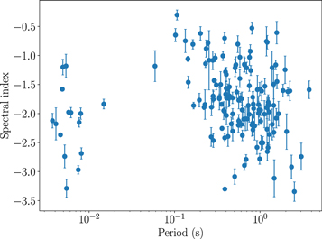
Figure 10. The distribution of spectral indices as a function of the pulsar's period. We see two clear populations representing the normal pulsars and the recycled pulsars. There is no clear evidence for steep spectral indices in the recycled pulsars compared to normal pulsars.
Download figure:
Standard image High-resolution image3.5. Polarization Fraction
We measured the circular polarization fraction in pulsars where we have simultaneous detections of the source in Stokes I and Stokes V (61/661). The polarization fractions range from 0.5% to ∼70%. For sources that were not detected in Stokes V, we report the upper limits. The polarization fractions of the matches and upper limits can be seen in Figure 11 (top panel). Note that polarization fractions below 1% may not be reliable: Pritchard et al. (2021) showed that a circular polarization of ∼1% (twice the median value reported by Pritchard et al. 2021) can be observed due to the leakage of flux into Stokes V in the RACS data, which is somewhat dependent on the position in the image. Other sources with upper limits to the polarization fraction are generally consistent with twice the all-sky Stokes V sensitivity limits, as seen in Figure 11. The black dashed line in Figure 11 shows the leakage cutoff and it can be seen that the majority of Stokes V detections are above this leakage level, while also being above the Stokes V sensitivity threshold.

Figure 11. Top: circular polarization fractions for the pulsars in our sample. Shown by the orange diamonds are the polarization fractions for sources detected in both Stokes I and Stokes V. Shown by the blue triangles are the upper limits in the cases of Stokes V nondetections, and shown by the black dashed line is the 1% polarization resulting from leakage into Stokes V (Pritchard et al. 2021). Shown by the vertical red dashed line is the Stokes I completeness limit (see Figure 3), and shown by the blue dashed line is the expected polarization fraction for a Stokes V flux density that is twice the all-sky RMS value in the RACS survey. Bottom: distribution of circular polarization fractions for pulsars detected in the RACS Stokes V survey. The blue shaded histogram shows the distribution for the 61/661 pulsars that are detected in Stokes V images, the black histogram shows the distribution of the polarization fractions from nondetections (using upper limits), and the green shaded region shows the polarization values from the literature (Gould & Lyne 1998; Sobey et al. 2021; Oswald et al. 2023). The distribution is peaked around 10%, with few pulsars having higher polarization fractions. The black dashed line shows the mean polarization fraction (4.6%) using the Kaplan–Meier estimate, and the black dotted line indicates the 1σ spread (8.6%) from the mean of the distribution.
Download figure:
Standard image High-resolution imageFor the Stokes V detections, the distribution of the polarization fractions is shown in the bottom panel of Figure 11. We find that most of the pulsar detections in the RACS survey have polarization fractions (median of ∼10%) that are consistent with pulsar observations in the literature (shown by the green shading in Figure 11; Gould & Lyne 1998; Sobey et al. 2021; Oswald et al. 2023), with a handful of them having higher polarization fractions. This, however, does not take into account the nondetections (upper limits) that dominate the sample (∼90% of the sample). In the presence of a combination of detections and upper limits, we follow Feigelson & Nelson (1985) in calculating the Kaplan–Meier estimator (Kaplan & Meier 1958) for the left-censored data (upper limits) and then estimating the mean of the combined data (detections and upper limits). We find that polarization fractions <13% are more likely (mean polarization fraction of 4.6%, with a large spread of ±8.4%) with an extended tail toward the higher values, using the Kaplan–Meier estimator, consistent with the median of the observed distribution.
4. Discussions
4.1. Luminosity Correlations
If the underlying source spectrum of a pulsar is known, we can calculate the expected luminosity in a given frequency band. However, this is usually not the case, since we do not know the pulsar's intrinsic emission spectrum. In addition, pulsar emission is beamed and the emission geometry is not well constrained, so following the literature (see Stollman 1987; Bagchi 2013 for reviews), we define the pseudo-luminosity as Sν
d2, in units of mJy kpc2, where Sν
is the flux density at a frequency ν and d is the distance to the pulsar estimated using the DM and a Galactic electron density model (Cordes & Lazio 2002; Yao et al. 2017). We computed the pseudo-luminosity for all the pulsars in our sample, using the measured flux densities at 888 MHz to look for any trends that the radio luminosity exhibits with the pulsar's parameters. In general, the radio luminosity function for pulsars is expressed as  and the indices (γ1, γ2) are estimated from observations (Gunn & Ostriker 1970; Proszynski & Przybycien 1984; Stollman 1987; Bagchi 2013). Gunn & Ostriker (1970) proposed that the radio pseudo-luminosity goes as
  , Proszynski & Przybycien (1984) found that it goes as
  , roughly corresponding to
  , where
  is the spindown luminosity, and Stollman (1987) proposed a B2/P dependence for pulsars with magnetic field <1013 G, the pulsars that are dominant in our sample. Hence, we look for any correlations between the pseudo-luminosity and the pulsars' intrinsic parameters (period/period derivative/characteristic age/magnetic field) and the quantities proposed in the literature.
Figure 12 shows correlation plots of the pseudo-luminosity versus the pulsar's parameters. The blue and orange scatters show the luminosity estimated using the Yao et al. (2017) and Cordes & Lazio (2002) electron density maps, respectively. In all cases, we found no clear evidence for any strong correlation with the estimated pseudo-luminosity. To compare this with the spindown luminosity, 11 we compute the radio luminosity (defined as the pseudo-luminosity × RACS bandwidth). We find that this radio luminosity (see the bottom right panel of Figure 12) does not scale accordingly with the spindown luminosity. The black dashed line shows the expected radio luminosity if it were powered by 0.01% of the spindown luminosity, implying that varying fractions of spindown luminosity power the radio emission. We also find that the luminosity ratio (radio to spindown) decreases with increasing spindown luminosity, and hence an increasing fraction of spindown luminosity powers the radio emission in pulsars as the pulsars age.
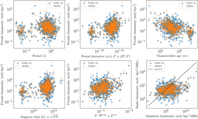
Figure 12. Correlation plots looking for any intrinsic correlation between the pseudo-luminosity and the pulsar's spin parameters, characteristic age, the surface dipole magnetic field strength, and other combinations of these parameters of interest (see Section 4.1). The distance to the pulsar is estimated using electron density models—the blue scatter plot shows the estimates using Yao et al. (2017) and the orange scatter plot shows the same using Cordes & Lazio (2002). A clear distinction between normal pulsars and recycled pulsars can be seen; especially in the spin parameter(s) space. No strong correlations between the pseudo-luminosity and any of the pulsar parameters are clearly seen. The bottom right plot shows the correlation between the radio luminosity (see Section 4.1) and the spindown luminosity. The black dashed line corresponds to 0.01% of spindown luminosity.
Download figure:
Standard image High-resolution imageTo quantify the level of this correlation, we use a nonparametric correlation test, the Spearman rank correlation test. Table 1 shows the Spearman correlation coefficients for the pseudo-luminosity versus the intrinsic pulsar's parameters and the existing correlations in the literature. Our sample is mainly dominated by normal pulsars, as is evident from Figure 12, and hence we restrict our correlation test to normal pulsars (we use the following cuts to distinguish normal from recycled pulsars: P = 100 ms,  , τc
= 300 Myr, and B = 5 × 10¹⁰ G). As expected from Figure 12, we do not find any strong evidence for the pseudo-luminosity being correlated with any parameter. We note that a recent study by Posselt et al. (2023), using data from Thousand Pulsar Array program found a correlation that is significant (in terms of its p-value), but the actual value of the correlation coefficient is similar to ours.
, τc
= 300 Myr, and B = 5 × 10¹⁰ G). As expected from Figure 12, we do not find any strong evidence for the pseudo-luminosity being correlated with any parameter. We note that a recent study by Posselt et al. (2023), using data from Thousand Pulsar Array program found a correlation that is significant (in terms of its p-value), but the actual value of the correlation coefficient is similar to ours.
Table 1. Correlation Coefficients for the Correlation between the Pseudo-luminosity (See Section 4.1) and the Pulsar Parameters and Existing Correlations in the Literature
| Parameter | Correlation Coefficient | |||
|---|---|---|---|---|
| DM Model | Yao et al. (2017) | Cordes & Lazio (2002) | ||
| Coefficient | p-value | Coefficient | p-value | |
| P | −0.15 | 4 × 10−04 | −0.21 | 5 × 10−07 |

| 0.16 | 1 × 10−04 | 0.30 | 2 × 10⁻¹³ |
| τc | −0.35 | 9 × 10⁻²¹ | −0.48 | 2 × 10−38 |

| 0.07 | 9 × 10−02 | 0.17 | 7 × 10−05 |

| 0.17 | 1 × 10−05 | 0.28 | 2 × 10⁻¹³ |
Note. We do not find a strong correlation in any of the above cases.
Download table as: ASCIITypeset image
4.2. Comparison with Other Surveys
We used the flux measurements from contemporary all-sky radio imaging surveys like the TIFR GMRT Sky Survey (TGSS; Frail et al. 2016, at 150 MHz), Murchison Widefield Array (MWA; Murphy et al. 2017, roughly at 200 MHz), and Very Large Array Sky Survey (VLASS; Gordon et al. 2021, at 3 GHz) to validate and compare our spectral fits (see Section 3.4). We selected the pulsars where the flux density measurements are available for at least five of the six different frequencies—150, 200, 400, 888, 1400, and 3000 MHz. Using the power-law spectra that we computed with RACS and PSRCAT (Section 3.4), we estimate the predicted flux density at these frequencies and compare it with the corresponding measured flux densities.
Figure 13 shows the comparison of the flux densities. The residuals (in logarithmic space) or the ratio between the observed fluxes and the modeled fluxes (in linear space; similar to Figure 7) are estimated using the power-law fit (see Section 3.4). If the source spectrum can be well modeled by a single power law, then the residuals are expected to be consistent with zero (the black dashed line) within error limits. However, any additional variation can be interpreted as a single power law being an inadequate description of the source spectrum. We see the evidence for a single power law greatly overestimating the flux density at the lower and higher frequencies in most of the pulsars (while underestimating it in a few).
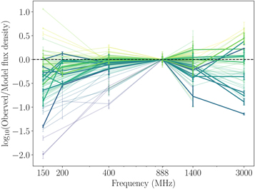
Figure 13. Comparison of the predicted flux densities at 150, 200, and 3000 MHz using the spectrum estimated with RACS and PSRCAT data, with the measured flux densities from other imaging surveys. Shown are the residuals (in logarithmic space) or the ratio between the observed fluxes and the modeled fluxes (in linear space); hence, any residual structure corresponds to the deviation from a single power law. We observe that in many of the pulsars, a single power law estimated from the ATNF and RACS data (see Figure 7 and Section 3.4) greatly overestimates the flux at these frequencies (while underestimating it in a few), hinting at the evidence for low- and high-frequency deviations from a power-law model. The color scheme represents the extent of the deviation from a power law (violet/yellow corresponds to maximum deficit/excess). These individual pulsar residuals are adjusted to 0 at 888 MHz.
Download figure:
Standard image High-resolution imageIn the sample of 35 pulsars that have flux density measurements at all five frequencies (150, 400, 888, 1400, and 3000 MHz), we tried to fit for a single power law, this time including all these flux density measurements.
Figure 14 (top panel) shows the residuals when the data were fit using a single power law. We find that a single power law does not adequately fit the data, as expected from the combined RACS and PSRCAT fits (see Section 3.4), with the median residuals (scaled by the measurement uncertainty) ∼3σ, 3σ, 2σ, and 4σ at 150, 400, 1400, and 3000 GHz, respectively, and a median reduced-χ2 of 7.5 (4 degrees of freedom or DOF). In this case, we find that the mean spectral index is softer, −1.53 ± 0.58, than the estimate derived using the three higher frequencies. We then tried to fit the data using a quadratic power law:

The bottom panel of Figure 14 shows the residuals in this case and shows that the variation is better modeled by a quadratic power law—the uncertainty-normalized median residuals are ∼0.3σ, 2σ, 0.6σ, 0.8σ, and a median reduced-χ2 of 1.7 (3 DOF)—rather than a pure power law. In many cases, the spectrum seems to exhibit low-frequency turnovers (Lorimer & Kramer 2004), and hence a quadratic variation in logarithmic space is able to better capture this trend. We also tried to fit the spectrum using a broken power law and found that it performs comparably to the quadratic power law. Figure 15 shows the spectra of the 14 pulsars that have flux density measurements in TGSS, MWA, and VLASS, in addition to the RACS and ATNF measurements. We see that the deviation from a simple power law can be quite common, with a quadratic power law/broken power law providing a much better fit to the data.
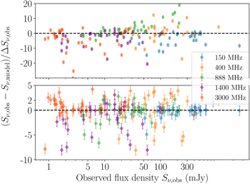
Figure 14. Residuals for the sample of 35 pulsars that have flux measurements at five frequencies (150, 400, 888, 1400, and 3000 MHz). The top panel shows the residuals when the data are fit using a pure power law, and the bottom panel shows the residuals when the data are fit using a quadratic power law. In both cases, the residuals are normalized using the measurement uncertainties.
Download figure:
Standard image High-resolution image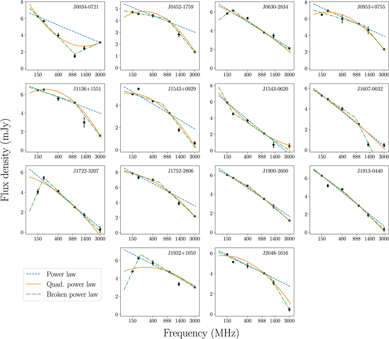
Figure 15. The spectra of the 14 pulsars that have flux density measurements available at 150, 200, 400, 888, 1400, and 3000 MHz. The spectra were modeled using a simple power law, a quadratic power law, and a broken power law. In many cases (e.g., J0452−1759), we see that the spectrum prefers a quadratic/broken power law over a simple power law, indicating that the deviation from a simple power law is quite common.
Download figure:
Standard image High-resolution imageHowever, we do caution that although a quadratic/broken power law provides a better fit than a single power law, there are still cases where it is inadequate in modeling the spectrum; for example, when the spectrum exhibits both low-frequency turnover and high-frequency turnup, a cubic variation might be needed. In summary, we find that the spectrum in a modest set of pulsars (as large as 40%) does not seem to exhibit a linear variation (in logarithmic frequency–flux density space), with higher-order nonlinear corrections providing better fits, and hence the use of simple power-law spectral fits in pulsars must be treated with caution.
5. Conclusions
We present crossmatches for the known pulsar population against the first release of the ASKAP RACS survey data. We find 600 Stokes I sources and 61 sources that have both Stokes I and Stokes V matches to known pulsars: we expect as many as 0.5% of these to represent false matches with 95% confidence. We also present the spectral characterization of these sources, finding that a single power law can be inadequate in many cases. Combining this with more low- and high-frequency data (TGSS, MWA, and VLASS), we find that a quadratic/broken power law represents a better fit to the spectral shape than a pure power law, revealing that the variation of flux density with frequency in logarithmic space can be nonlinear and high-/low-frequency deviations can be very common. The data presented here can be added to repositories like Swainston et al. (2022) and used in more advanced spectral modeling. We present the polarization information of these sources, finding that the estimated fraction is consistent with the ones in the literature. We looked at the variation of the pseudo-luminosity and its correlation with any intrinsic pulsar parameters and found no evidence for a strong correlation, also revealing that varying fractions of spindown luminosity power the radio luminosity and this fraction increases as the pulsar ages. The addition of reliable flux density measurements through current/future imaging surveys will help in the accurate modeling of the underlying source spectrum of the pulsars.
Acknowledgments
A.A., A.E., M.J., and D.K. are supported by National Science Foundation (NSF) Physics Frontiers Center award numbers 1430284 and 2020265. A.A. and D.K. are further supported by NSF grant AST-1816492. R.S. is supported by NSF grant AST-1816904. Parts of this research were conducted by the Australian Research Council Centre of Excellence for Gravitational Wave Discovery (OzGrav), project number CE170100004. This scientific work uses data obtained from Inyarrimanha Ilgari Bundara/the CSIRO Murchison Radio-astronomy Observatory. We acknowledge the Wajarri Yamaji People as the Traditional Owners and native title holders of the Observatory site. CSIRO's ASKAP radio telescope is part of the Australia Telescope National Facility (ATNF). The operation of ASKAP is funded by the Australian Government, with support from the National Collaborative Research Infrastructure Strategy. ASKAP uses the resources of the Pawsey Supercomputing Research Centre. The establishment of ASKAP, Inyarrimanha Ilgari Bundara, the CSIRO Murchison Radio-astronomy Observatory, and the Pawsey Supercomputing Research Centre are initiatives of the Australian Government, with support from the Government of Western Australia and the Science and Industry Endowment Fund. The Parkes radio telescope is part of the Australia Telescope National Facility (https://ror.org/05qajvd42), which is funded by the Australian Government for operation as a National Facility managed by CSIRO.
Facility: ASKAP - .
Software: NumPy (Harris et al. 2020), Matplotlib (Hunter 2007), AstroPy (Astropy Collaboration et al. 2013, 2018).
Appendix A: Image Cutouts
Shown in this Appendix are the sample detection images for the three representative cases where a pulsar is
- (i)detected in both Stokes I and Stokes V images
- (ii)detected in Stokes I image but marginally detected in Stokes V image and
- (iii)detected in only Stokes I image (Figure 16).

Figure 16. 3' image cutouts of Stokes I and Stokes V intensity maps depicting three different cases: combined Stokes I and V detection (PSR J0711−6830), Stokes I detection with a marginal Stokes V detection (PSR J0528+2200), and a purely Stokes I detection (PSR J0509+0856). Shown in the red ellipse is the detected RACS source, and shown in the crosshairs is the pulsar's position, as reported in the ATNF catalog.
Download figure:
Standard image High-resolution imageAppendix B: Flux Measurements
Given in Table B1 are the astrometric and flux measurements of the pulsars in our sample that have both 400 MHz and 1.4 GHz flux measurements from PSRCAT.
Table B1. Astrometric and Spectral Measurements for Pulsars in Our Sample Whose Spectrum Can Be Described by a Simple Power Law
| Pulsar | R.A. | Decl. | Flux Density a | Index | ||||||
|---|---|---|---|---|---|---|---|---|---|---|
| RACS | ATNF | Other Imaging Surveys | ||||||||
| 888 MHz | 400 MHz | 1.4 GHz | 150 MHz | 200 MHz | 3 GHz | |||||
| (mJy) | (mJy) b | (mJy) | (mJy) | (mJy) | (mJy) | (mJy) | ||||
| J0030+0451 | 00h30m27 2 2 | +04°51'41'' | 2.2( 8) | 1.74 | 7.9( 2) | 1.1( 3) | 45( 4) | ⋯ | ⋯ | −1.58(3) |
| J0152−1637 | 01h52m107 | −16°37'53'' | 4.1( 4) | 1.06 | 20 ( 4) | 2.1( 4) | 88( 7) | ⋯ | ⋯ | −1.8 (2) |
| J0525+1115 | 05h25m563 | +11°15'20'' | 3.7( 96) | 0.08 | 19.5( 9) | 1.9( 2) | 32( 6) | ⋯ | ⋯ | −1.84(4) |
| J0528+2200 | 05h28m522 | +22°00'04'' | 14 ( 2) | 0.46 | 57 ( 5) | 9 ( 2) | ⋯ | ⋯ | 1.5( 4) | −1.6 (2) |
| J0543+2329 | 05h43m097 | +23°29'07'' | 15.7( 7) | 0.22 | 29 ( 1) | 10.7( 7) | ⋯ | ⋯ | 4.7( 2) | −0.79(5) |
| J0601−0527 | 06h01m589 | −05°27'49'' | 6.1( 4) | 0.05 | 22.7( 9) | 2.6( 5) | 32( 6) | ⋯ | ⋯ | −1.67(8) |
| J0614+2229 | 06h14m169 | +22°29'58'' | 8.4( 9) | 0.12 | 29 ( 1) | 3.3( 2) | ⋯ | ⋯ | ⋯ | −1.72(5) |
| J0629+2415 | 06h29m056 | +24°15'41'' | 8.8( 8) | 0.12 | 31 ( 2) | 3.2( 4) | ⋯ | ⋯ | ⋯ | −1.7 (1) |
| J0659+1414 | 06h59m483 | +14°14'23'' | 3.4( 5) | 0.94 | 6.5( 6) | 2.7( 2) | ⋯ | ⋯ | ⋯ | −0.70(9) |
| J0729−1836 | 07h29m324 | −18°36'42'' | 4.8( 7) | 0.27 | 11.2( 7) | 1.9( 5) | ⋯ | ⋯ | ⋯ | −1.2 (1) |
| J0820−1350 | 08h20m263 | −13°50'56'' | 12.8( 4) | 0.56 | 102 ( 6) | 6 ( 2) | 207( 8) | 160( 7) | ⋯ | −2.59(8) |
| J0823+0159 | 08h23m096 | +01°59'12'' | 4.5( 6) | 0.82 | 30 ( 5) | 4 ( 2) | 40( 4) | ⋯ | ⋯ | −2.2 (2) |
| J0837+0610 | 08h37m055 | +06°10'17'' | 12.8( 7) | 4.55 | 89 ( 14) | 5 ( 1) | 766( 9) | 286( 13) | ⋯ | −2.4 (2) |
| J0908−1739 | 09h08m381 | −17°39'40'' | 4.5( 4) | 2.1 | 16 ( 1) | 4 ( 2) | 46( 8) | ⋯ | ⋯ | −1.6 (1) |
| J0908−4913 | 09h08m354 | −49°13'05'' | 23.7( 5) | 0.43 | 28 ( 3) | 20 ( 1) | ⋯ | ⋯ | ⋯ | −0.30(9) |
| J0922+0638 | 09h22m140 | +06°38'24'' | 12.2( 5) | 1.2 | 52 ( 6) | 10 ( 3) | 216( 8) | 100( 13) | ⋯ | −1.7 (1) |
| J0953+0755 | 09h53m093 | +07°55'37'' | 217.0( 9) | 206.24 | 400 ( 200) | 100 ( 40) | 656( 14) | 1072( 17) | 10.1( 2) | −1.1 (5) |
| J1012−5857 | 10h12m483 | −58°57'48'' | 4.6( 4) | 0.01 | 15 ( 2) | 1.9( 1) | ⋯ | ⋯ | ⋯ | −1.72(9) |
| J1041−1942 | 10h41m362 | −19°42'12'' | 4.5( 4) | 0.34 | 28 ( 6) | 2.3( 9) | ⋯ | ⋯ | ⋯ | −2.2 (3) |
| J1239+2453 | 12h39m402 | +24°53'50'' | 34.4( 7) | 12.65 | 110 ( 33) | 23 ( 5) | 136( 6) | ⋯ | 2.7( 2) | −1.2 (3) |
| J1257−1027 | 12h57m046 | −10°27'05'' | 2.0( 5) | 0.17 | 12 ( 1) | 1.2( 3) | ⋯ | ⋯ | ⋯ | −1.9 (2) |
| J1455−3330 | 14h55m479 | −33°30'46'' | 1.3( 5) | 0.46 | 9 ( 1) | 0.7( 4) | ⋯ | ⋯ | ⋯ | −2.0 (1) |
| J1532+2745 | 15h32m103 | +27°45'50'' | 2.9( 4) | 1.31 | 13 ( 2) | 0.8( 3) | 40( 4) | ⋯ | ⋯ | −2.0 (2) |
| J1543−0620 | 15h43m301 | −06°20'45'' | 8.0( 5) | 2.79 | 40 ( 6) | 2.0( 7) | 369( 4) | 91( 12) | 1.8( 4) | −2.1 (2) |
| J1610−1322 | 16h10m427 | −13°22'22'' | 3.2( 6) | 0.13 | 16 ( 1) | 1.1( 3) | ⋯ | ⋯ | ⋯ | −2.13(5) |
| J1614+0737 | 16h14m408 | +07°37'33'' | 1.5( 4) | 0.3 | 9.6( 8) | 0.6( 3) | 297( 28) | ⋯ | ⋯ | −2.3 (3) |
| J1623−0908 | 16h23m175 | −09°08'49'' | 1.2( 4) | 0.03 | 6.0( 4) | 0.6( 1) | 37( 4) | ⋯ | ⋯ | −1.9 (1) |
| J1703−1846 | 17h03m510 | −18°46'14'' | 1.9( 4) | 0.05 | 11 ( 1) | 0.7( 2) | 163( 8) | ⋯ | ⋯ | −2.2 (2) |
| J1709−1640 | 17h09m264 | −16°40'57'' | 17.6( 5) | 1.93 | 47 ( 5) | 14 ( 3) | 82( 6) | ⋯ | ⋯ | −1.1 (1) |
| J1709−4429 | 17h09m427 | −44°29'07'' | 16.9( 6) | 0.11 | 25 ( 4) | 12.1( 7) | ⋯ | ⋯ | ⋯ | −0.7 (1) |
| J1720−2933 | 17h20m341 | −29°33'17'' | 5.3( 5) | 0.12 | 32 ( 4) | 1.7( 1) | 383( 13) | ⋯ | ⋯ | −2.38(9) |
| J1722−3207 | 17h22m029 | −32°07'46'' | 12.2( 5) | 0.01 | 61 ( 4) | 5.4( 11) | 57( 12) | 229( 37) | 1.3( 4) | −2.01(9) |
| J1741−0840 | 17h41m225 | −08°40'31'' | 5.6( 5) | 0.09 | 29 ( 8) | 1.4( 4) | ⋯ | ⋯ | ⋯ | −2.3 (3) |
| J1757−2421 | 17h57m293 | −24°22'03'' | 11.8( 13) | 0.01 | 20 ( 4) | 7.2( 4) | ⋯ | ⋯ | 2.4( 3) | −0.9 (1) |
| J1759−2205 | 17h59m241 | −22°05'32'' | 3.8( 95) | 0.01 | 20 ( 2) | 1.3( 1) | 139( 17) | ⋯ | ⋯ | −2.2 (1) |
| J1807−0847 | 18h07m379 | −08°47'43'' | 34.9( 9) | 0.06 | 65 ( 4) | 18 ( 4) | 94( 12) | ⋯ | 4.6( 3) | −0.81(8) |
| J1813+4013 | 18h13m133 | +40°13'39'' | 2.8( 5) | 0.18 | 8 ( 2) | 1.1( 2) | ⋯ | ⋯ | ⋯ | −1.6 (2) |
| J1820−0427 | 18h20m525 | −04°27'36'' | 26.1( 11) | 0.04 | 157 ( 6) | 10.1( 2) | 975( 8) | 499( 51) | ⋯ | −2.18(3) |
| J1825−0935 | 18h25m306 | −09°35'22'' | 17.6( 9) | 0.8 | 36 ( 3) | 10 ( 2) | 412( 11) | ⋯ | 0.9( 2) | −0.9 (1) |
| J1829−1751 | 18h29m431 | −17°51'03'' | 23.6( 6) | 0.01 | 78 ( 5) | 11 ( 2) | 102( 8) | ⋯ | 3.9( 3) | −1.51(8) |
| J1833−0338 | 18h33m419 | −03°39'02'' | 9.4( 6) | 0.01 | 89 ( 5) | 2.8( 3) | 230( 11) | ⋯ | ⋯ | −2.79(8) |
| J1836−1008 | 18h36m539 | −10°08'09'' | 14.4( 11) | 0.01 | 54 ( 6) | 4.8( 1) | 65( 15) | ⋯ | ⋯ | −1.8 (1) |
| J1841+0912 | 18h41m559 | +09°12'08'' | 4.8( 8) | 0.28 | 20 ( 1) | 1.7( 1) | ⋯ | ⋯ | ⋯ | −1.96(6) |
| J1844+1454 | 18h44m548 | +14°54'14'' | 4.1( 5) | 0.29 | 20 ( 2) | 1.8( 4) | 105( 7) | ⋯ | 1.7( 5) | −1.9 (2) |
| J1844−0433 | 18h44m334 | −04°33'12'' | 3.2( 9) | 0.01 | 8.1( 7) | 1.1( 1) | ⋯ | ⋯ | ⋯ | −1.6 (1) |
| J1847−0402 | 18h47m228 | −04°02'13'' | 12.6( 7) | 0.01 | 75 ( 3) | 4.9( 3) | 945( 14) | ⋯ | ⋯ | −2.19(6) |
| J1848−0123 | 18h48m236 | −01°23'58'' | 34 ( 3) | 0.01 | 79 ( 6) | 15 ( 3) | 420( 18) | ⋯ | 2.2( 3) | −1.2 (1) |
| J1849−0636 | 18h49m064 | −06°37'06'' | 4.1( 5) | 0.01 | 26 ( 1) | 1.4( 1) | 203( 8) | ⋯ | 1.1( 3) | −2.33(8) |
| J1850+1335 | 18h50m355 | +13°35'56'' | 2.3( 4) | 0.08 | 6 ( 1) | 0.8( 2) | ⋯ | ⋯ | ⋯ | −1.5 (2) |
| J1857+0943 | 18h57m363 | +09°43'16'' | 8.9( 5) | 1.63 | 20 ( 6) | 5.0( 5) | ⋯ | ⋯ | 2.4( 2) | −1.2 (2) |
| J1900−2600 | 19h00m475 | −26°00'44'' | 32.6( 5) | 1.55 | 131 ( 12) | 15 ( 3) | 408( 15) | 299( 13) | 3.4( 3) | −1.7 (1) |
| J1901+0331 | 19h01m318 | +03°31'06'' | 17.6( 13) | 0.01 | 165 ( 10) | 4.2( 4) | 437( 17) | ⋯ | 1.0( 3) | −2.89(8) |
| J1902+0556 | 19h02m428 | +05°56'26'' | 3.7( 96) | 0.01 | 15 ( 2) | 1.2( 1) | ⋯ | ⋯ | ⋯ | −2.0 (1) |
| J1902+0615 | 19h02m503 | +06°16'33'' | 4.3( 11) | 0.01 | 22 ( 4) | 1.6( 3) | ⋯ | ⋯ | ⋯ | −2.1 (2) |
| J1904+1011 | 19h04m024 | +10°11'36'' | 1.6( 6) | 0.01 | 4.4( 3) | 0.6( 7) | ⋯ | ⋯ | ⋯ | −1.6 (1) |
| J1905−0056 | 19h05m278 | −00°56'40'' | 2.0( 5) | 0.01 | 9.8( 6) | 0.7( 1) | 38( 7) | ⋯ | ⋯ | −2.1 (1) |
| J1909+0254 | 19h09m383 | +02°54'50'' | 2.6( 5) | 0.01 | 21 ( 1) | 0.6( 7) | ⋯ | ⋯ | ⋯ | −2.78(9) |
| J1910−0309 | 19h10m297 | −03°09'54'' | 2.7( 4) | 0.01 | 27 ( 3) | 0.6( 7) | 124( 6) | ⋯ | ⋯ | −3.1 (1) |
| J1913−0440 | 19h13m542 | −04°40'47'' | 19.1( 4) | 0.06 | 118 ( 9) | 6.8( 14) | 528( 9) | 176( 26) | 1.4( 3) | −2.3 (1) |
| J1915+1009 | 19h15m300 | +10°09'44'' | 3.5( 8) | 0.01 | 23 ( 2) | 2.0( 4) | ⋯ | ⋯ | ⋯ | −2.0 (2) |
| J1915+1606 | 19h15m280 | +16°06'30'' | 1.8( 5) | 0.01 | 4 ( 1) | 0.9( 2) | ⋯ | ⋯ | ⋯ | −1.2 (3) |
| J1916+0951 | 19h16m323 | +09°51'26'' | 5.3( 7) | 0.11 | 20 ( 2) | 1.6( 3) | 64( 10) | ⋯ | ⋯ | −1.9 (1) |
| J1922+2110 | 19h22m534 | +21°10'42'' | 3.3( 6) | 0.01 | 30 ( 1) | 1.4( 2) | 131( 9) | ⋯ | ⋯ | −2.5 (1) |
| J1926+1648 | 19h26m454 | +16°48'35'' | 3.2( 5) | 0.01 | 8 ( 1) | 1.3( 2) | ⋯ | ⋯ | ⋯ | −1.4 (2) |
| J1932+2020 | 19h32m080 | +20°20'45'' | 4.5( 6) | 0.01 | 29 ( 2) | 1.2( 4) | 258( 8) | ⋯ | ⋯ | −2.4 (2) |
| J1943−1237 | 19h43m253 | −12°37'41'' | 2.4( 5) | 0.21 | 12.9( 6) | 1.2( 2) | 37( 6) | ⋯ | ⋯ | −1.9 (1) |
| J1949−2524 | 19h49m256 | −25°23'58'' | 1.3( 4) | 0.22 | 5.2( 6) | 0.4( 1) | ⋯ | ⋯ | ⋯ | −2.0 (2) |
| J2002+3217 | 20h02m043 | +32°17'18'' | 2.2( 5) | 0.02 | 5.5( 5) | 1.2( 1) | ⋯ | ⋯ | ⋯ | −1.2 (1) |
| J2006−0807 | 20h06m163 | −08°07'02'' | 9.7( 4) | 1.1 | 20 ( 3) | 4.7( 9) | ⋯ | ⋯ | ⋯ | −1.0 (2) |
| J2013+3845 | 20h13m103 | +38°45'42'' | 9.2( 11) | 0.01 | 26 ( 1) | 6.4( 5) | ⋯ | ⋯ | 2.7( 3) | −1.14(7) |
| J2018+2839 | 20h18m038 | +28°39'54'' | 53.6( 11) | 8.61 | 314 ( 30) | 30 ( 13) | 282( 10) | ⋯ | ⋯ | −2.2 (1) |
| J2029+3744 | 20h29m238 | +37°44'03'' | 3.3( 8) | 0.01 | 18 ( 2) | 0.6( 1) | 132( 14) | ⋯ | ⋯ | −2.7 (2) |
| J2046+1540 | 20h46m392 | +15°40'32'' | 3.4( 5) | 0.13 | 11.5( 9) | 1.7( 3) | ⋯ | ⋯ | ⋯ | −1.5 (1) |
| J2046−0421 | 20h46m002 | −04°21'26'' | 3.5( 6) | 0.25 | 20 ( 1) | 1.7( 5) | 26( 5) | ⋯ | ⋯ | −2.1 (2) |
| J2055+3630 | 20h55m314 | +36°30'22'' | 7.6( 9) | 0.01 | 28 ( 1) | 2.6( 1) | 64( 7) | ⋯ | ⋯ | −1.89(4) |
| J2124−3358 | 21h24m439 | −33°58'45'' | 8.2( 5) | 5.58 | 17 ( 4) | 4.5( 2) | ⋯ | ⋯ | 2.1( 4) | −1.2 (1) |
| J2129−5721 | 21h29m226 | −57°21'14'' | 2.4( 3) | 0.19 | 14 ( 2) | 1.0( 7) | ⋯ | ⋯ | ⋯ | −2.1 (1) |
| J2317+2149 | 23h17m579 | +21°49'51'' | 3.9( 7) | 0.94 | 15 ( 3) | 0.9( 5) | ⋯ | ⋯ | ⋯ | −1.9 (3) |
Notes. Flux densities: ATNF—400 MHz and 1.4 GHz (Manchester et al. 2005); TGSS—150 MHz (Frail et al. 2016); MWA—200 MHz (Murphy et al. 2017); and VLASS—3 GHz (Gordon et al. 2021).
a Numbers quoted in parentheses are 1σ errors on the last digits of the flux densities. b Errors in flux densities due to diffractive scintillation are quoted in addition to measurement uncertainties.A machine-readable version of the table is available.
Footnotes
- 8
Using a patch of radius 1°.
- 9
As part of a search of circularly polarized sources in the Variable and Slow Transients (Murphy et al. 2021) survey (J. Pritchard et al. 2023, in preparation), we identified a source in the vicinity of the pulsar B1353−62. Follow-up observations with the Ultra-Wide Low (Hobbs et al. 2020) receiver on the Parkes 64 m "Murriyang" radio telescope determined that the polarized source was in fact B1353−62, with pulsations visible from 700 MHz to 4 GHz. We therefore update the position of the pulsar to be R.A. 13h56m55.4s and decl.
 , with an uncertainty (including systematic errors) of 25 in either direction, and include it in this analysis.
 - 10
We note that these measurements come from a variety of sources and may have mixed reliability.
- 11
The spindown luminosity is estimated assuming a moment of inertia I = 1045 g cm2. We also scale this by 4π, taking into account the uncertainty in the emission geometry.
