
Abstract
The effect of strain on the ferroelectricity of HfO2 thin films after crystallization was investigated by applying uniaxial mechanical strains to Au/HfO2/TiN metal–ferroelectric–metal (MFM) capacitors. The remnant polarization (2Pr) of MFM capacitors increased when tensile strain was applied during polarization switching. This phenomenon should not be attributed to phase transformation from the non-ferroelectric to the ferroelectric phase, taking account of the fast relaxation of 2Pr after removal of the mechanical strain and the fact that the crystal structure of HfO2 thin films evaluated by grazing incidence X-ray diffraction measurement was not changed by the tensile strain.
Export citation and abstract BibTeX RIS

Content from this work may be used under the terms of the Creative Commons Attribution 4.0 license. Any further distribution of this work must maintain attribution to the author(s) and the title of the work, journal citation and DOI.
Since the first discovery of ferroelectricity in Si-doped HfO2 in 2011, 1) ferroelectric HfO2-based thin films have been considered as promising materials for ferroelectric devices such as ferroelectric random access memory and ferroelectric field-effect transistors. 2–5) It has been reported that ferroelectricity also appears in HfO2 films with other dopants such as Y, 6,7) Zr, 8) Ge, 9) La, 10) Sr, 11) Al 12) and N, 13) and even in undoped HfO2. 14) The ferroelectricity of HfO2-based thin films has been thought to originate from the metastable orthorhombic (o) phase (Pca21). 15–17) Many approaches have been proposed to stabilize the ferroelectric phase, such as controlling the film thickness, doping concentration and interface engineering. 13,18–21) Moreover, it has been pointed out that tensile strain is one of the important factors promoting the formation of the o-phase in HfO2-based thin films. It has been reported that tensile strain during the annealing process through the thermal expansion of top and bottom electrodes enhanced the formation of the ferroelectric phase in HfO2 thin films. 22–25) In addition, our previous research has suggested that increase in the remnant polarization of HfO2 thin films during electric field cycling (waking-up) is also correlated with the process-induced tensile strain in the HfO2 thin films. 26–28) These studies focused on the effects of process-induced strain during the crystallization process. However, the effects of strain after the crystallization process at RT on the ferroelectricity of HfO2 thin films are not yet clear. Here, we focused on the effects of mechanical strain after crystallizing HfO2 thin films.
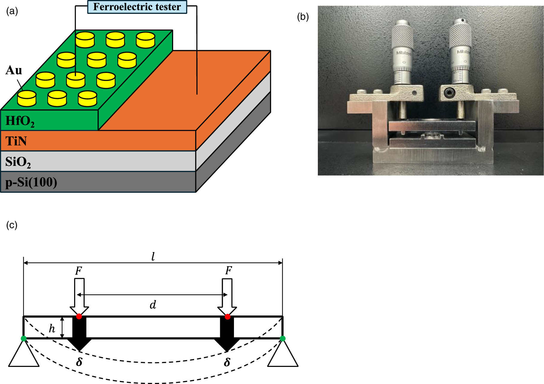
In this study, we directly and quantitatively investigated the effects of strain after the crystallization process on the ferroelectricity of undoped HfO2 thin films by applying mechanical strain to Au/HfO2/TiN metal–ferroelectric–metal (MFM) capacitors using a four-point bending jig during polarization switching at RT. Au/HfO2/TiN MFM capacitors were fabricated as follows. As a substrate, a 500-μm thick 4-in p-type Si(100) wafer was thinned down to a thickness of 200 μm so that a large mechanical strain could be applied. After thermal oxidation, a 60-nm thick TiN layer was deposited by DC sputtering in Ar and N2 ambient at a substrate temperature of 400 °C as a bottom electrode. The sample was transferred to another chamber, and a 30-nm thick HfO2 film was deposited on the TiN electrode by RF sputtering in an Ar ambient of 0.1 Pa at RT in the chamber with a base pressure of 1.0 × 10⁻⁶ Pa followed by post-deposition annealing in a N2 ambient at 650 °C for 100 s. The deposition rate of HfO2 was 1.1 nm min−1. An additional annealing process was subsequently carried out in an O2 ambient at 400 °C for 30 s to reduce oxygen deficiency in the HfO2 films. Finally, Au was deposited by resistive heating vapor deposition as the top electrode. A schematic diagram of the sample structure is shown in Fig. 1(a). A uniaxial mechanical strain was applied to the Au/HfO2/TiN MFM capacitors using a four-point bending jig during the electric field cycling test, as shown in Figs. 1(b) and 1(c). The amount of uniaxial strain (ε) was estimated from the displacement at the force points of the jig (δ) with the following equation:

where h, l and d are the thickness of the sample, the distance between the supporting points of the jig and the distance between the force points of the jig, respectively. The polarization–electric field (P–E) curves of the MFM capacitors were measured using a ferroelectric tester with an electric field of ±4 MV cm−1 at a frequency of 5 kHz, and the endurance properties were characterized by applying a fatigue wave of ±2.7 MV cm−1 at a frequency of 20 kHz. The crystal structure of HfO2 thin films was analyzed by out-of-plane grazing incidence X-ray diffraction (GIXRD). The incident angle of XRD measurement was set to 0.45°.

Fig. 1. (a) Schematic diagram of the sample structure. (b) Photo of the four-point bending jig for Au/HfO2/TiN MFM capacitors. (c) Schematic of the four-point bending method for Au/HfO2/TiN MFM capacitors. The red circles and green circles indicate the force points and support points, respectively.
Download figure:
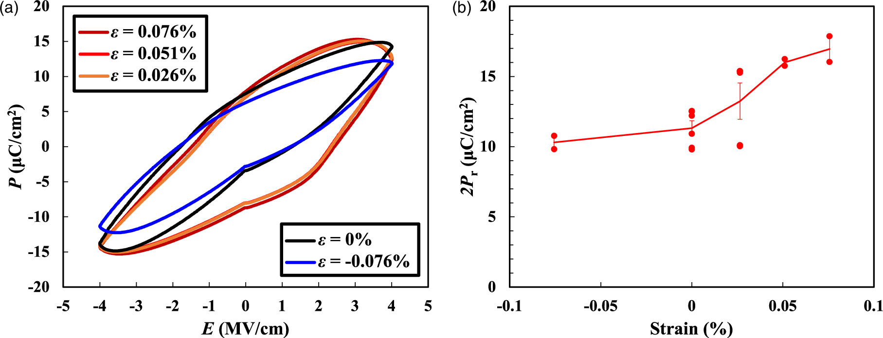
Standard image High-resolution imageFigure 2(a) shows the initial P–E properties of the Au/HfO2/TiN MFM capacitors with application of the various mechanical strains using four-point bending. The relationship between the strain and the remnant polarization (2Pr = Pr +−Pr −) extracted from P–E curves at 0 MV cm−1 is shown in Fig. 2(b). In this figure, the positive and negative strains indicate tensile and compressive strain, respectively. It was found that 2Pr increased by increasing the applied tensile strain. The same trend was observed in the 2Pr estimated by the PUND (positive up negative down) method, which can exclude the component of the leakage current (data not shown). It should be noted that the maximum 2Pr of 17 μC cm−2 was observed when a tensile strain of 0.08% was applied, which is 1.5 times larger than the one observed in the case without strain (0%). On the other hand, no significant difference in 2Pr was observed under compressive strain compared with the case without strain. Therefore, we conclude that 2Pr increases due to the application of tensile strain during polarization switching even after the crystallization of the film.

Fig. 2. (a) P–E properties of Au/HfO2/TiN MFM capacitors measured under various mechanical strains. (b) Relationship between the strain and 2Pr. The positive and negative strains indicate tensile and compressive strain, respectively. The error bars indicate the standard errors of the data on the plots.
Download figure:
Standard image High-resolution imageNext, the endurance properties of Au/HfO2/TiN MFM capacitors with the application of various mechanical strains during field cycling was investigated as shown in Fig. 3(a). The ratio of waking-up (rwoke) was defined from the switching polarization (Psw) in the pristine state and the maximum Psw during field cycling, and the relationship between the strain and rwoke is shown in Fig. 3(b). No significant difference in rwoke was observed regardless of the direction and amount of strain. On the other hand, the number of cycles required to obtain the maximum Psw was ∼3 × 10³ when a tensile strain of 0.08% was applied, while the number of cycles at the maximum Psw was ∼1 × 10⁴ in the case without strain. Therefore, we found that the mechanical tensile strain could have an effect on facilitating the waking-up of HfO2 thin films.
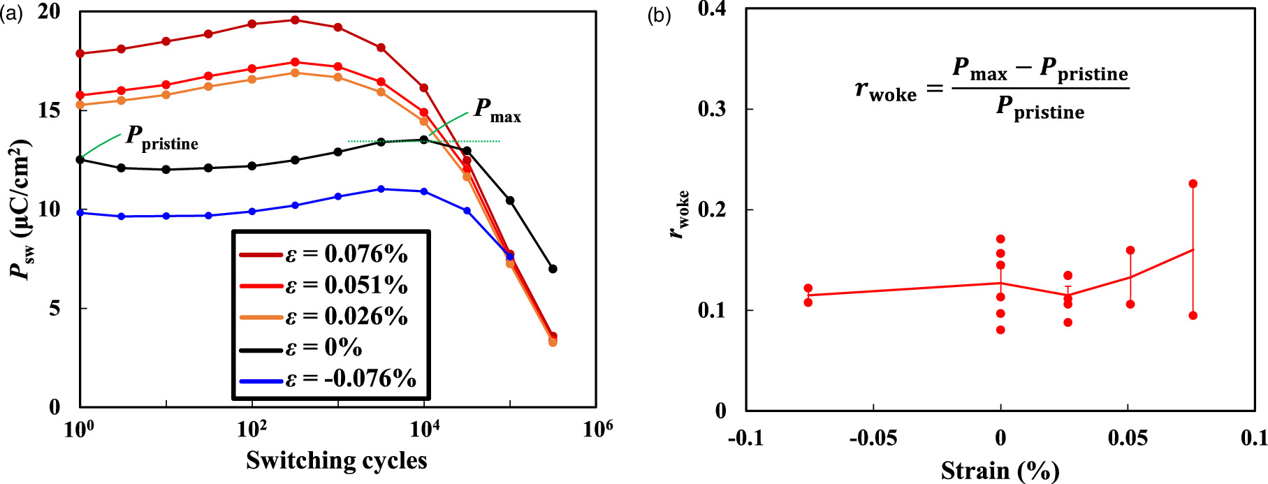
Fig. 3. (a) Endurance properties of Au/HfO2/TiN MFM capacitors measured under various mechanical strains. (b) Relationship between the strain and rwoke. The positive and negative strains indicate tensile and compressive strain, respectively. The error bars indicate the standard errors of the data on the plots.
Download figure:
Standard image High-resolution imageAfter removing the tensile strain, the MFM capacitors were left at RT for various time up to 5600 min, then P–E measurements of the MFM capacitors were carried out. Figure 4 shows the relationship between the time after removing the tensile strain and 2Pr normalized by  where 2Pro and 2Pr∞ are the values of 2Pr just after the tensile strain was removed and after infinite time, respectively. For the value of 2Pr∞, the observed 2Pr after 5600 min was employed in this analysis. The 2Pr gradually decreased with time and returned to the original value of the MFM capacitors before the application of the mechanical strain. We estimated that this relaxation phenomenon follows the equation

where τ is the relaxation time. According to previous research, it took more than 20 h for phase transformation from o- and tetragonal (t) phases to the monoclinic (m) phase in HfO2 thin films at a temperature of 200 °C. 29) Therefore, it would be natural to expect an even longer time for such phase transformation. On the other hand, the observed relaxation time of 2Pr at RT after removal of the tensile strain was approximately 1–5 h, which was estimated from the calculated line in Fig. 4 assuming the relationship of Eq. (2). This faster relaxation should not be due to phase transformation from the ferroelectric to the non-ferroelectric phase. These results indicate that the increase in 2Pr should be induced by the application of tensile strain with a smaller activation energy than that required for phase transformation.
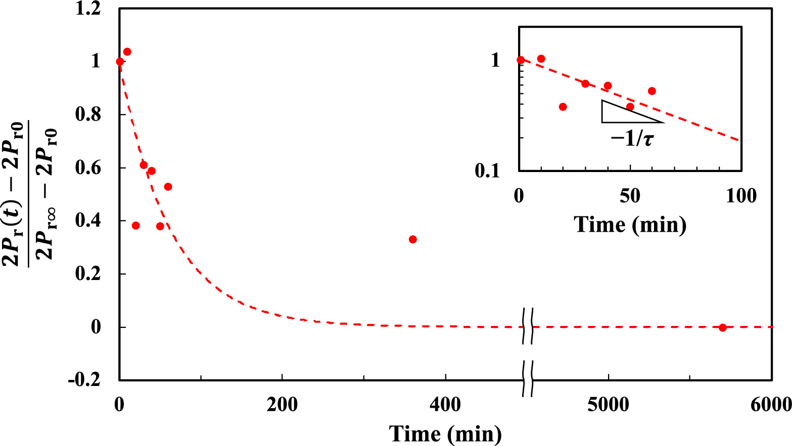
Fig. 4. Relationship between the time after removing the tensile strain and normalized 2Pr. The dotted curve indicates the calculated line for the case of τ = 1 h. The inset shows the data taking the log of the normalized 2Pr in the vertical axis for t = 0–100 min.
Download figure:
Standard image High-resolution imageTo confirm the lack of phase transformation while such an anomalous increase of the 2Pr occurs, GIXRD measurements were conducted for the HfO2/TiN samples without Au top electrodes under mechanical strain. Figure 5(a) shows the GIXRD patterns of HfO2 films with tensile strain. The peaks originating from the m-, o-, t- and cubic (c) phases were observed. Note that the peaks of o( ), t(
), t( ) and c(
 ) are located so close each other that it is difficult to distinguish them. The relative ratio of the o-, t- or c-phases (ro/t/c) was defined from the peak areas of m(
 ) (
) ( ), o(
), o( )/t(
)/t( )/c(
)/c( ) (
) ( ) and m(
 ) (
) ( ), using the following equation:

No significant increase in ro/t/c was observed regardless of the application of tensile strain, as shown in Fig. 5(b), suggesting that the increase in 2Pr was not due to phase transformation from the non-ferroelectric to ferroelectric o-phase. These results are consistent with the above consideration on the observed faster relaxation phenomenon of 2Pr after removing the tensile strain at RT in Fig. 4. We may have to take account of a possibility that the change in the film properties might not be observable just by the application of strain but only appear after polarization, if we assume the 2Pr enhancement is triggered by the polarization cycling. Actually, in our previous research it was clarified that one of the important factors driving the phase transformation during field cycling to cause waking-up is process-induced strain, such as the doping-induced strain in the films. 26–28) However, since the mechanically induced strain applied in this study (∼0.1%) was not so large as the indicated process-induced strain (∼1%) in our previous study, 26–28) the amount of strain in this study was not sufficient to cause the phase transformation in HfO2 thin films during field cycling. Therefore, the anomalous increase in 2Pr in this study should be attributed to the enhancement of polarization without increase in the volume fraction of the ferroelectric o-phase in the film. One of the possible explanations for these enhancements of polarization is that the pinning effect could be weakened by the tensile strain. It is known that the polarization of the ferroelectric domain in HfO2 thin films is pinned by the trapped charges at the interface of HfO2 thin films and the electrodes or by the oxygen defects in the HfO2 thin films. 30) It is possible that the pinning effect could be weakened by the polarization under tensile strain, resulting in the larger 2Pr. This explanation is consistent with the result of the promoted waking-up effect under tensile strain, as shown in Fig. 3(a), because one of the origins of waking-up is the de-pinning of the ferroelectric domain during field cycling. 30,31) Another possible explanation is that the orientation of the crystal grains of the o-phase in HfO2 thin films is aligned by the application of tensile strain. For the ferroelectric o-phase in HfO2, the lattice constant along the a-axis is the largest and the direction of polarization is along the c-axis. When the in-plane tensile strain is applied to the crystal grains of the o-phase it is possible that the a-axis of the crystal grains of the o-phase tends to align in the in-plane direction, which could cause an increase in the alignment of c-axis orientation in the out-of-plane direction. As a result, o-phase grains can make a greater contribution to polarization along the out-of-plane direction of the HfO2 films, which leads to the larger 2Pr. Since these explanations can be applied to thinner HfO2 films, we consider that the enhancement of 2Pr by the application of tensile strain is a general effect for ferroelectric HfO2 thin films. However, the magnitude of enhancement of 2Pr might be affected by the thickness of the HfO2 films, the crystallinity of the films and the crystal orientation.

Fig. 5. (a) GIXRD patterns for HfO2 under various strains of 0%, 0.05% and 0.08%. (b) Relationship between the relative ratio of o-/t-/c-phases, calculated using peak areas of the o-/t-/c-phase ( ) and the m-phase (
 and
and  ) and the applied strain during the GIXRD measurement.
Download figure:
Standard image High-resolution image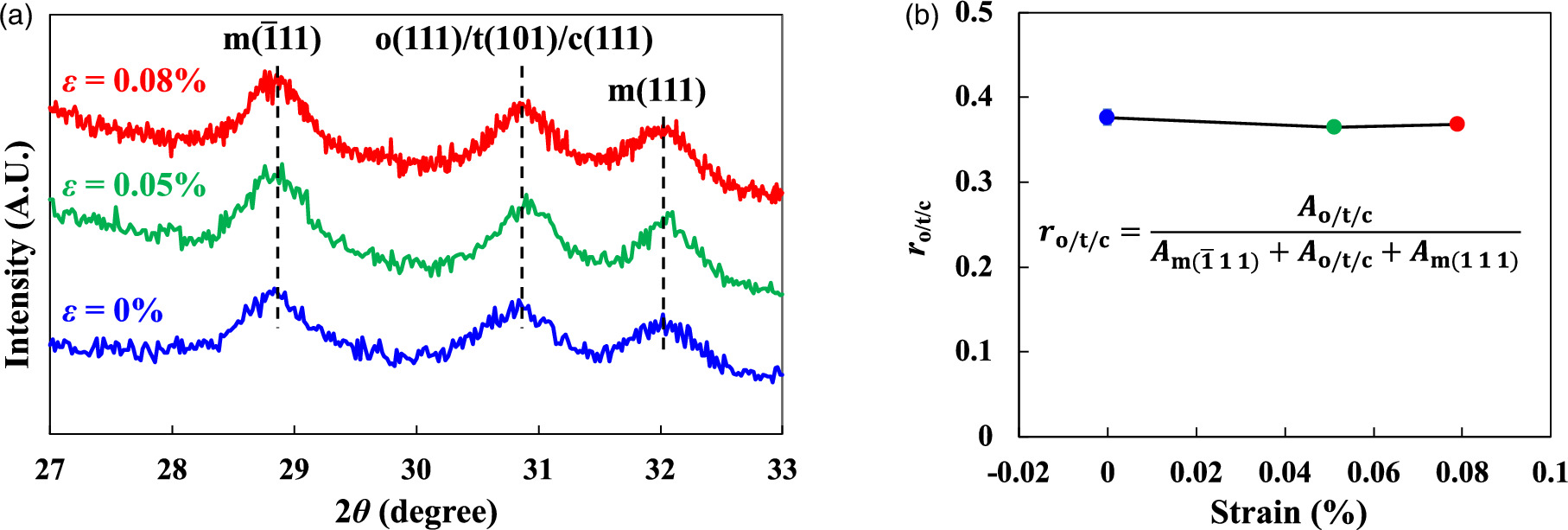
In conclusion, the effect of uniaxial mechanical strain after the crystallization process on the ferroelectricity and crystallinity of HfO2 thin films was investigated using the four-point bending method. It was found that the application of tensile strain resulted in a larger 2Pr of HfO2 thin films, while compressive strain did not induce significant change. This phenomenon should be attributed to the enhancement of polarization without phase transformation from the non-ferroelectric to the ferroelectric o-phase, because fast relaxation was observed after the removal of tensile strain at RT and no significant phase transformation was observed in the GIXRD patterns with application of mechanical strain.
Acknowledgments
This work was partly supported by the JSPS Bilateral Joint Research Project (project number JPJSBP120217402).