
Abstract
In this work, we present the biquadratic field Hbq contribution to increase a frequency of spin-torque oscillation (STO) in an orthogonal magnetization structure in simulation, and realize such an orthogonal structure by preparing Co/Pt lamination as the bottom perpendicular magnetic anisotropy layer, Cr or Cu as the spacer, and experimentally realize Fe90Co10 as the top free layer. Our observations of the Cr-spacer sample reveal a notable challenge in achieving magnetic saturation, underscoring the role of Hbq in suppressing magnetization reversal and its potential to broaden the STO current range and increase the STO frequency. This leads to the manifestation of spin-transfer-torque oscillations in an orthogonal structure, bolstered by robust biquadratic magnetic coupling, thus attaining high and stable STOs in the simulations.
Export citation and abstract BibTeX RIS
1. Introduction
Since the discovery that magnetization dynamics can be controlled by the spin-transfer torque (STT), 1,2) extensive research has been conducted on its applications in data storage and memory. In particular, STT has been employed in various cutting-edge technologies including microwave-assisted magnetic recording in hard-disk drives and magnetoresistive random-access memories. 3–8) Recently, the emergence of spin-torque oscillations (STOs) has sparked considerable interest for their potential applications in neural networks. 9–11) While conventional ferromagnetic transition metals exhibit STO frequencies in the order of several gigahertz, 12–15) antiferromagnetic materials can theoretically manifest STO frequencies reaching the terahertz range. 16–29) This assumption is grounded in various theoretical investigations, including those concerning experimental magnetic-resonance frequencies. However, the practical realization of usable STOs in antiferromagnets remains elusive, mainly because of the large exchange-coupling interactions between neighboring ions. In response to this challenge, artificial magnetic structures have been proposed as promising approaches for increasing the STO frequency. These structures encompass synthetic antiferromagnetic coupling layers 30–32) and quasi-antiferromagnets featuring biquadratic magnetic coupling, 33,34) offering a potential alternative for amplifying the STO frequency. In contrast, orthogonal magnetization multilayers, comprising magnetic layers with both in-plane and perpendicular magnetic anisotropies, have demonstrated high spin-transfer efficiency, rendering them suitable candidates for generating STOs with elevated frequencies and reduced power consumption. 35–43) However, the increased efficiency, which is attributed to the diminished angle between the magnetizations of the two layers, poses a conundrum. Specifically, this limits the current–density range within which a stable STO can be sustained as frequent magnetization switching events occur.
To address this challenge, we introduce biquadratic magnetic coupling
33,34,44–56) between the two magnetic layers within the orthogonal configuration. This strategic addition suppresses complete magnetization switching, thereby enhancing the stability of the STO. Biquadratic magnetic coupling is an interlayer exchange interaction between two ferromagnetic (FM) layers separated by a thin spacer. In general, the magnetic coupling energy E is expanded to a higher-order equation by considering the quadratic term as E = −A12
M1 M2 −B12 (M1M2)2, where M1 and M2 are the unit magnetizations in the first and second FM layers, respectively, and A12 and B12 are the bilinear and biquadratic coupling coefficients, respectively. A12 contributes 0° or 180° magnetic coupling, whereas B12 contributes +/−90° magnetic coupling. Typically, +/−90° coupling is realized under the conditions of |A12| < 2|B12| and B12 < 0, using a suitable layer as a spacer. The values of A12 and B12 depend on the spacer layer material and magnetic material, respectively, and values of 0 to –0.24 erg cm−2 for A12 and −0.005 to –2.0 erg cm−2 for B12 have been reported.
33,34,44–56)
M2 −B12 (M1M2)2, where M1 and M2 are the unit magnetizations in the first and second FM layers, respectively, and A12 and B12 are the bilinear and biquadratic coupling coefficients, respectively. A12 contributes 0° or 180° magnetic coupling, whereas B12 contributes +/−90° magnetic coupling. Typically, +/−90° coupling is realized under the conditions of |A12| < 2|B12| and B12 < 0, using a suitable layer as a spacer. The values of A12 and B12 depend on the spacer layer material and magnetic material, respectively, and values of 0 to –0.24 erg cm−2 for A12 and −0.005 to –2.0 erg cm−2 for B12 have been reported.
33,34,44–56)
In a previous study, we had elucidated the efficacy of biquadratic coupling to realize quasi-antiferromagnetic Co90Fe10, resulting in an augmentation of the STO frequency. 33,34) However, this enhancement was capped at 15 GHz when subjected to a realistic current density like 10.0 × 10⁷ A cm−2, using a multilayer configuration featuring two in-plane magnetization layers. Subsequently, through comprehensive simulations, we successfully observed that the biquadratic magnetic field H bq exerted an influence: it broadened the attainable current range of the STOs by effectively suppressing magnetization reversal. 42,43) This effect is particularly useful for increasing the STO frequency in orthogonal structures. In light of these simulation results, the present study embarks on an experimental endeavor aimed at validating the presence of Hbq within an orthogonal structural arrangement and assessing its potential to suppress magnetization reversal. This experimental investigation is a pivotal step toward further elucidating the fundamental underpinnings of biquadratic coupling in orthogonal structures. In addition to the abstract of the International Conference on Solid State Device and Materials, 57) we present the results of the in-plane structure below.
2. Experimental methods
In our experiments, we fabricated five different samples on a thermally oxidized Si wafer by DC sputtering, with all measurements reported in nanometers (nm), as schematically illustrated in Fig. 1. The sample configurations are as follows: Buffer/Ir22Mn78 (5)/Fe90Co10 (A) (2)/Cr tCr/Fe90Co10 (B) (2)/Cu 6/Fe90Co10 (C) (2.5)/Cap, where tCr is 1, 2, and 3 nm for Samples 1, 2, and 3, respectively, and Buffer/[Co (0.5)/Pt (0.5)]4/Co (0.5)/Spacer/Fe90Co10 (2)/Cap where the Spacer is Cu 5 nm and Cr 1 nm for Samples 4 and 5, respectively. Samples 1–3 were designed as in-plane structures, to investigate the magnitude of the biquadratic magnetic coupling introduced by the Cr spacer layer and examine the relationship between this coupling and the thickness of the Cr film. After deposition, they were annealed with an in-plane field of 0.46 T at 270 K in vacuum for 2 h to pin the magnetization of Fe90Co10 (A) by an exchange coupling with the Ir22Mn78 layer. As a result, the magnetization of Fe90Co10 (B) was coupled with that of Fe90Co10 (A) at angles of +/− 90° through the Cr spacer layer. Notably, these samples featured an anomalous FM layer, Fe90Co10 (C), which served as a reference for magnetization.

Fig. 1. Schematic film images of samples: (a) in-plane structure and (b) orthogonal structure.
Download figure:
Standard image High-resolution imageIn contrast, Samples 4 and 5 were configured as orthogonal structures. Sample 4 with a 5 nm Cu spacer ensured that there was no magnetic coupling between the bottom [Co (0.5)/Pt (0.5)]4/Co (0.5)/and top Fe90Co10 (2) layers. In contrast, the 1 nm Cr spacer of Sample 5 was employed to establish strong biquadratic magnetic coupling between the top and bottom layers. When an external magnetic field was applied perpendicular to the plane, the magnetization direction of the top layer aligned upward with the field. Therefore, both the samples exhibited opposing static magnetic fields, relative to the applied external field. However, when the spacer was composed of Cr, the biquadratic magnetic coupling introduced an additional field, denoted as Hbq . The direction of Hbq was opposite to that of the external magnetic field, with the anticipated effect of suppressing magnetization reversal.
The magnetization was measured at RT using a vibrating-sample magnetometer and superconducting quantum interference device. The roughness of Cr and Cu was measured using X-ray reflection (XRR) with SmartLab (Rigaku) and GenX was used to analyze the XRR profile. 58) In GenX, the figure of merit (FOM) serves as an indicator of the fitting curve's alignment with the experimental data. We achieved reasonable results by iteratively repeating XRR fittings until the FOM reached a value below 1.1 e−1.
3. Experimental results
Figure 2 presents the MH curves for the in-plane–structured samples with Cr spacer thicknesses of 1, 2, and 3 nm, as the magnetic field is swept in a direction perpendicular to the Fe90Co10 (A) layer. Notably, the MH curves reveal two distinct magnetization reversals, each of which corresponds to a particular magnetization sequence depicted in states (1)–(4), as illustrated in Fig. 2. In the state (1), the magnetization of the sample becomes fully saturated in an alignment with the direction of the applied magnetic field. As the system evolves from the state (1) to the state (2), the magnetization within the Fe90Co10 (A) layer gradually reorients itself from the direction of the applied field toward the pinned direction, facilitating near-zero-field flipping of the Fe90Co10 (C) layer in response to the applied magnetic field. In the state (2), the Fe90Co10 (A) layer is fixed in one direction by the Ir22Mn78 layer, while the magnetization of the Fe90Co10 (B) layer is coupled at an angle of ±90° relative to the Fe90Co10 (A) layer. While transitioning from the state (2) to the state (3), the biquadratic magnetic coupling between the Fe90Co10 (A) and Fe90Co10 (B) layers dissolves, causing the magnetization to align gradually in the direction of the applied magnetic field. In the state (3), the magnetization attains saturation parallel to the direction of the applied field. Notably, the state (4) mirrors the state (2) in terms of the magnetic configuration. Importantly, the applied magnetic-field values at which magnetization reversal occurs in states (2) and (4) provide a means to evaluate the strength of the biquadratic magnetic coupling.

Fig. 2. (a) MH loops of the in-plane structure. Magnetic fields were applied at 90° with respect to the exchange bias field. (b) Schematic images of the magnetization in the Fe90Co10 (A), (B), and (C) layers, where the white and black arrows denote the magnetization and purple arrows denote the applied magnetic field. The states of (1)–(4) in (b) correspond to (1)–(4) in (a).
Download figure:
Standard image High-resolution imageFigure 2 clearly illustrates that, among the samples tested, the one featuring a 1 nm Cr spacer exhibits the most robust biquadratic magnetic coupling. As the thickness of the Cr film increases, the strength of this coupling gradually diminishes, with the lowest value observed for 3 nm Cr. Specifically, the magnetic field at the second magnetization reversal, corresponding to the strength of the magnetic coupling, is 0.01 T, 0.006 T, and 0.005 T for the spacer of the 1 nm, 2 nm, and 3 nm Cr layer, respectively. These findings underscore the superiority of the 1 nm Cr spacer as the optimal spacer, among Samples 1–3, to achieve strong and effective biquadratic magnetic coupling. Therefore, we use the 1 nm Cr spacer for the orthogonal structure in the following. Here, the magnetic coupling depends on the roughness of the spacer. Previously, the cross-sectional TEM image and XRR analysis showed that the spacer roughness is about 0.3 nm. 33,56) Such a small roughness is necessary to restrain the orange peel coupling, leading the smaller bilinear coupling than the biquadratic coupling.
Figure 3 presents the MH curves for the orthogonal structure samples, featuring both Cr and Cu spacers, with the magnetic field swept perpendicular to the sample plane. Notably, our observations confirm that the Co/Pt bottom layer exhibits perpendicular magnetic anisotropy with a coercivity (Hc) of approximately 0.03 T. In contrast, the saturation field for the Fe90Co10 top layer differs, measuring 2 and 1.6 T for the samples with Cr and Cu spacers, respectively. Also, we show the XRR data for Sample 4–5 in Fig. 4. The fitting results showed that the spacer Cr and Cu have roughness of 0.10 nm and 0.41 nm, respectively. What is important is that the roughness of the Cr spacer is as small as 0.10 nm. When the spacer is thin and its roughness is large, the magnetic coupling like the orange peel coupling caused by the roughness is not negligible. Compared to this, when the spacer is as thick as 5 nm, the magnetic coupling originated from the roughness is small enough to be ignored. Hence, it is not needed to consider the effect of the roughness on the magnetic coupling through the Cr spacer with sufficient small roughness and the Cu spacer with 5 nm thickness. Note that the deviation observed in the curve during the full reflection stage may be attributed to the effect of sample fringe because the sample size is small.

Fig. 3. (a) MH loops of the orthogonal structure. Magnetic fields were applied perpendicular to the plane. (b) Schematic images of the magnetization in the top and bottom layers, where the red and black arrows denote the magnetization and applied magnetic field. The states of (1)–(4) in (b) correspond to (1)–(4) in (a).
Download figure:
Standard image High-resolution image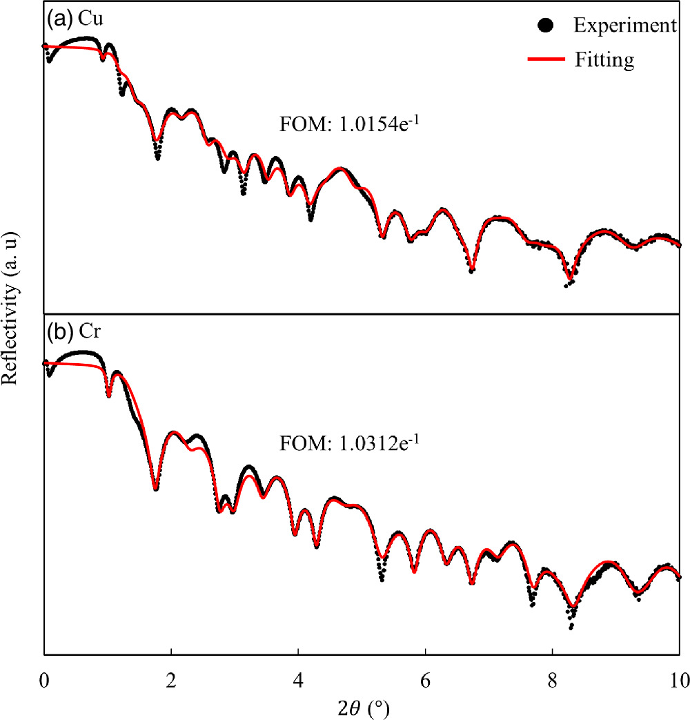
Fig. 4. XRR results and fitting curves. (a) Cu spacer sample and, (b) Cr spacer sample.
Download figure:
Standard image High-resolution imageIn the high-field regime exceeding +/− 2 T [i.e. for states (1) and (3)], the collective magnetization of both the bottom and top layers becomes saturated along the z-direction. As the size of the applied field is reduced below +/− 1.6 T, state (2), the Fe90Co10 top layer begins to rotate, aligning itself along the easy axis within the sample plane. This clearly demonstrates the anticipated orthogonal structure of the magnetized films in the top and bottom layers.
The observed disparity in the saturation field (Hsat) for Fe90Co10 is attributed to the biquadratic magnetic coupling between these two magnetic layers. Specifically, we estimate the biquadratic coupling parameter (B12) to be −0.6 for the Cr spacer and 0.0 for the Cu spacer, within this structural context.
Consequently, our findings confirm the successful realization of an effective field arising from biquadratic coupling in an orthogonal magnetization structure. This implies that a higher electrical current is required to induce magnetization inversion when Cr serves as the spacer, thereby broadening the range of electrical current levels capable of sustaining a stable STO through the introduction of biquadratic magnetic coupling.
4. Numerical experiments
4.1. Simulation model
In our simulations, the STO was investigated by solving the Landau–Lifshitz–Gilbert (LLG) equation, which incorporates an STO term. The effective field (Heff ) guiding the dynamics of the system is composed of the following constituents: Heff = HK + Hexf + Hex + HST + Hbl + Hbq , where HK represents the magnetic anisotropy field; Hexf denotes the influence of the external magnetic field; Hex characterizes the exchange coupling field determined by the exchange stiffness constant A; HST accounts for the stray field dependent on the saturation magnetization of the magnetic material; Hbl signifies the bilinear exchange field determined by the bilinear coefficient A12; and Hbl designates the biquadratic exchange field determined by the biquadratic coefficient B12. When considering two FM layers, denoted as i and j, with normalized magnetizations mi and mj , respectively, the biquadratic exchange field (Hbq ) can be expressed as follows: 59)
where Ms,i denotes the saturation magnetization of the magnetic material in the top layer. The xy plane and z-axis are in the in-plane and perpendicular directions, respectively, as shown in Fig. 5.
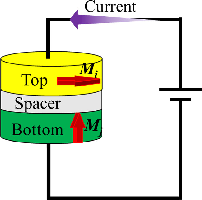
Fig. 5. Calculation model with an orthogonal structure.
Download figure:
Standard image High-resolution imageIn the orthogonal configuration, we designate the top and bottom FM layers as i and j, respectively, each exhibiting distinct magnetic anisotropy characteristics: i with in-plane anisotropy and j with perpendicular anisotropy. In this context, the biquadratic exchange field for layer i, denoted by Hbq,i , is formulated as follows:

This relationship indicates that the direction of Hbq aligns with mj when B12 > 0 and opposes mj when B12 < 0. Given that the biquadratic magnetic coupling becomes prominent under condition B12 < 0, the direction of Hbq counters mj when the biquadratic exchange magnetic coupling manifests. The STT term within the LLG equation aligns parallel to mj . Consequently, the biquadratic exchange coupling Hbq assumes a direction opposite to that of the STT. Considering that Hbq plays a dominant role within the effective field Heff , along with HST , the biquadratic exchange coupling Hbq emerges as a pivotal factor in averting complete magnetization reversal from an in-plane to a perpendicular orientation, thereby promoting the stability of STO. Consequently, the magnetic moment of the top layer is expected to exhibit gyroscopic motion around the z axis. Here, we did not consider the Joule heating effect on magnetization dynamics.
In our proposed model, the orthogonal configuration comprises a structure with a 2 nm thick FePt bottom layer, 2 nm spacer, and Co90Fe10 top layer. The purpose that we selected FePt is to obtain a large Hk, which is essential for maintaining the perpendicular magnetization of the bottom layer. However, in our experimental setup, due to the challenges associated with growing FePt at high temperatures and its more complex preparation process, we opted for the alternating sputtering of Co/Pt to create the bottom layer. This Co/Pt layer also exhibits a large Hk, enabling the maintenance of perpendicular magnetization within an orthogonal structure. The device has a disk-shaped geometry with a diameter of 320 nm. The FePt bottom layer exhibits perpendicular anisotropy, characterized by a coercivity (Hk ) of 15000 Oe and saturation magnetization (Ms) of 800 emu cc−1. 60,61) In contrast, the top layer exhibits in-plane magnetic anisotropy. Specifically, Co90Fe10 exhibits a Hk of 35 Oe, Ms of 1450 emu cc−1, and damping constant (α) of 0.035. 33)
For simplicity, we set the bilinear coefficient A12 to 0 and biquadratic coefficient B12 to −0.6, where B12 corresponds to an experimentally reported value for the spacer Cr. Both A12 and B12 represent values based on previous reports.
Our simulation employed a magnetic unit cell of size 5 nm × 5 nm × 2 nm, and the calculations were conducted on a grid comprising 64 × 64 × 3 cells. The exchange stiffness constant A was set to 1 × 10⁻⁶ erg cm−1 and the gyromagnetic ratio γ was 1.76 × 10⁷ Oe−1 s−1. The simulation time step (dt) was set as 10 fs.
In the initial phase, we computed the magnetization relaxation following saturation along the y axis. Subsequently, current was supplied to the layers, originating from the top and proceeding to the bottom layer.
4.2. Simulation results and discussion
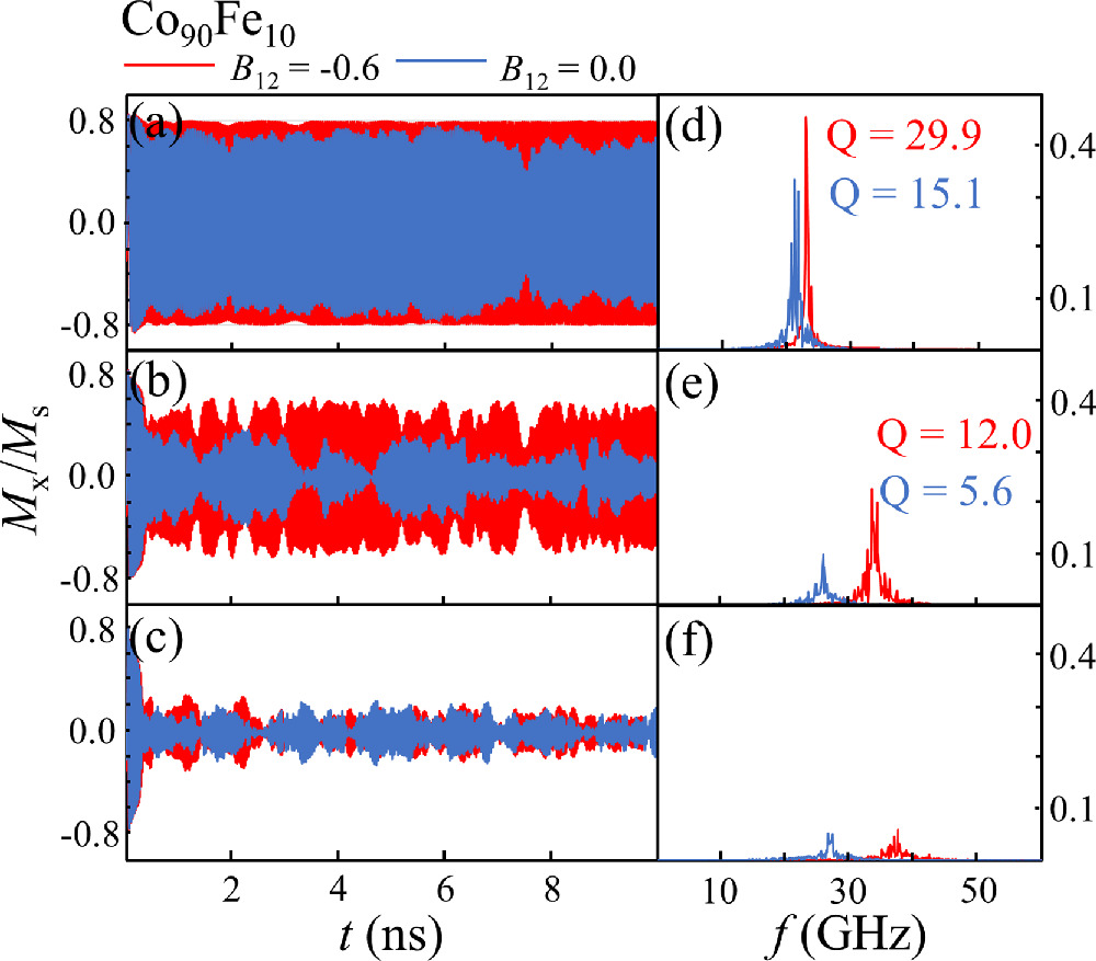
We present the simulated time-domain magnetization precessions when B12 is 0 and −0.6 in Figs. 6(a)–6(c) and the corresponding Fast Fourier transform (FFT) spectra in Figs. 6(d)–6(f). The applied electrical current densities are 10.0 × 10⁷ (a), 15.0 × 10⁷ (b), and 20.0 × 10⁷ A cm−2 (c). At a relatively low current density of 10.0 × 10⁷ A cm−2, as shown in Figs. 6(a) and 6(d), a stable STO can be achieved regardless of whether B12 is set to 0.0 or −0.6. However, upon increasing the current density to 15.0 × 10⁷ A cm−2, as depicted in (b) and (e), the STO becomes unstable at B12 = 0.0 owing to magnetization switching, whereas the STO persists at B12 = −0.6. With a further increase in the current density to 20.0 × 10⁷ A cm−2, as shown in (c) and (f), the STO becomes small and eventually the magnetization reverses in both cases of B12 at 0.0 and −0.6. Additionally, the sample with B12 = −0.6 exhibited a more stable STO with an almost immutable Mx /Ms , a higher quality factor Q, and higher frequency than that with B12 = 0.0. These results indicate that, by introducing biquadratic magnetic coupling, we can expand the range of the electrical current density to achieve a stable STO and increase the frequency. Thus, higher current densities can be employed, leading to higher STO frequencies. Therefore, a spacer material with high biquadratic magnetic coupling is required for a stable HF STO.
Fig. 6. Time-domain magnetization precessions Mx/Ms of the top layer Co90Fe10 and the FFT spectra when B12 is 0.0 or −0.6. The current densities are 10.0 × 10⁷ A cm−2 (a), (d), 15.0 × 10⁷ A cm−2 (b), (e), and 20.0 × 10⁷ A cm−2 (c), (f).
Download figure:
Standard image High-resolution image
5. Conclusions
Our investigation into the magnetic properties of the biquadratic magnetic coupling within the Fe90Co10/Cr/Fe90Co10 layer revealed a noteworthy dependence on the thickness of the Cr spacer. In the descending order of coercivity, we observed the following trend: Cr 1 nm > Cr 2 nm > Cr 3 nm. This compelling finding positioned Cr as a promising candidate for achieving HF current-driven magnetization oscillations. Furthermore, we successfully fabricated multilayer structures featuring orthogonal structures, confirming the presence and efficacy of biquadratic magnetic coupling. This implied that a larger electrical current was required to induce magnetization inversion when Cr was used as the spacer. This augmented the electric-current region capable of sustaining a stable STO. Through a comprehensive numerical investigation, we conducted an in-depth exploration of the STO within magnetic multilayers featuring orthogonal magnetization configurations. By strategically introducing biquadratic magnetic coupling, we achieved a significant expansion in the range of electric current levels conducive to a stable STO. In summary, our study not only advances our understanding of STO within orthogonal magnetization structures but also underscores the pivotal role of biquadratic magnetic coupling in enhancing the operational range of stable STOs. These findings hold significant promise for the development of the next-generation spintronic devices and their applications.
Acknowledgments
This study was supported by the Japan Society for the Promotion of Science, KAKENHI (Grant No. JP19K04471, JP22H01557), Micron Foundation, MEXT Initiative to Establish Next-Generation Novel Integrated Circuit Centers (X-NICS), The Center for Spintronics Research Network (Osaka), and JST, the establishment of university fellowships towards the creation of science and technology innovation, Grant No. JPMJFS2132.