

Abstract
In this study, we demonstrate a new concept of large-scale strain sensors whose construction is based on a hybrid structure of a conductive intermittent pattern with embedded sensing elements made of a functional resistive ink. Because the electrical resistance of the intermittent conductive pattern (made of silver) was much lower than that of the resistance of sensing elements made of carbon-based inks, the sensitivity of the entire sensor depends almost selectively on the properties of the sensing elements, which is a key feature of the demonstrated sensor. The developed large-scale strain sensors were tested during static and dynamic bending deformations, demonstrating good strain sensitivity (gauge factor: 13.26) and no hysteresis within the investigated strain range. This sensor construction may be especially suitable for manufacturing sensors longer than those demonstrated herein (20 cm) and with a desirable electrical resistance.
Export citation and abstract BibTeX RIS
1. Introduction
Strain sensors have evolved significantly during the last decade. The progress in additive manufacturing, which is widely used for the fabrication of various flexible electronic devices, 1,2) enables the designing of new types of strain sensors using diverse materials. Conventional metal foil strain gauges are typically made of a copper–nickel alloy through a photolithography etching process. 3) However, materials such as constantan, which has a low temperature coefficient of resistance, are not commercially available in the form of inks dedicated to additive manufacturing. Hence, printed strain sensors are generally made of other strain-sensitive materials based on graphite, 4–6) silver, 7,8) PEDOT:PSS 9–11) graphene, 12) carbon nanotubes (CNT), 13–15) or composites of these materials. 16–19) The selection of materials is generally related to specific target applications, including wearable strain sensors for human motion detection, 20–22) structural health monitoring (SHM), 23–27) or many other diverse applications such as strain monitoring in tires, 28) hip prosthesis, 29) or handguns. 30)
All the above-mentioned studies show great promise for the practical use of printed flexible strain sensors. However, all these sensors have one common feature. They are entirely constructed using a strain-sensitive material that defines both the sensor shape and sensing properties. In our previous studies, we demonstrated an alternative concept for a strain sensor whose design was based on the hybrid construction of a conductive intermittent pattern with embedded single droplets of resistive carbon black 31) and CNT 32) inks providing strain sensitivity. The principle of operation of such a sensor is similar to that of conventional sensors and is based on monitoring of the electrical resistance changes in the entire sensor structure subjected to mechanical deformations. However, the key feature of the developed sensor is that the electrical resistance of the intermittent conductive pattern (made of silver) was much lower than the resistance of sensing elements made of carbon-based ink. It was shown that, owing to such a configuration, the sensitivity of the entire sensor depends almost selectively on the properties of the electrically resistive sensing elements. Nonetheless, the previously demonstrated sensors were relatively short (2 cm in length). 31,32) Although this sensor length is sufficient for practical use, some applications require strain measurements over relatively long distances, such as SHM. However, for long sensors, the main issue with the printable sensors made of the most common materials is relatively high electrical resistance. Electrical resistance is important, especially with regard to power consumption (if the resistance is too low) and electrical noise level (if the resistance is too high). These two aspects are important from the point of view of reliable practical applications where sensors are often incorporated into the Internet of Things systems, where low power consumption and low noise level are essential. Thus, the implementation of the segmented intermittent structure demonstrated in this study can be especially suitable for manufacturing relatively long strain sensors with resistance within a desirable range.
This work began with a comparative analysis of short (2 cm) sensors made of carbon black and CNT inks. This preliminary analysis of sensors was intended to select a functional material, with regard to strain sensitivity, for the fabrication of the longer sensors, whose analysis was the main goal of this study. After the selection of an appropriate material, the concept of the strain sensor with the intermittent structure was implemented for the manufacturing of large-scale sensors, the length of which was over 20 cm. The collected results showed that the developed large-scale sensor made of carbon black ink had good strain sensitivity, linear output signal, and no hysteresis within the analyzed strain range.
2. Experimental methods
2.1. Fabrication process
The preparation of both types of sensors, the short and long, begins with the printing of the intermittent conductive patterns. Silver ink (TAIYO INK ELEPASTE NP1) was screen printed onto a 20 μm thick polyethylene terephthalate (PET) substrate, with dimensions of 30 cm × 30 cm. A stainless steel mesh (Asada Mesh HS-D 650/14) was used for high-resolution printing. The short sensors had 20.3 mm long and 0.3 mm wide construction, divided into five segments, each 3.7 mm long. The gap between the two segments was 0.3 mm [Fig. 1(a)]. After printing, such patterns were cured in a conventional convection oven at 100 °C for 30 min. In the next step, the free spaces of the intermittent structure were filled with a functional material that provided strain sensitivity.
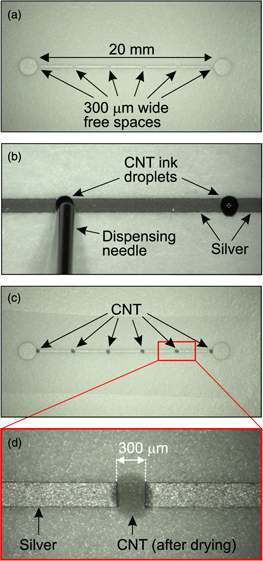
Fig. 1. (Color online) (a) Printed pattern of the intermittent structure made of silver ink. (b) Deposition of single CNT ink droplets. (c) Top view of the fabricated short strain sensor. (d) Zoom in the dried CNT ink droplet.
Download figure:
Standard image High-resolution imageIn this study, a short strain sensor made of CNT ink (VC101, Chasm Advanced Materials) was compared with a sensor with the same construction but made of a carbon black ink (TOYOBO DY-200L-2). The functional inks were used in a very small quantity through the deposition of single droplets [Fig. 1(b)], using a dispenser (Musashi ML-5000XII). The dispenser had adjustable pressure and discharge times. A pressure of 0.35 MPa and discharge time of 70 ms and 50 ms were set for the carbon black ink and CNT, respectively. Such settings were selected to form droplets that were sufficiently large to fill the 0.3 mm × 0.3 mm free spaces in the intermittent pattern and to provide electrical contact between the consecutive silver segments [Fig. 1(c)]. After the deposition of inks, the entire sensor structures were dried in a convection oven at 130° C for 30 min. The electrical resistance of the dried single CNT droplets [Fig. 1(d)] was 219.5 ± 13.4 Ω, while the entire hybrid (silver–CNT) structure had a resistance of 1303 ± 41 Ω. For comparison, the electrical resistance of dried single droplets made of carbon black was 32.6 ± 2.3 Ω, while the entire hybrid (silver–carbon black) structure had a resistance of 199.3 ± 8.4 Ω.
The large-scale sensors had a 225 mm long and 1 mm wide sensing grid. The intermittent structure was fabricated using the same silver ink. Two types of long sensors that differed by the number of sensing elements distributed along the same sensor length were fabricated. Their construction was divided into 41 segments and 81 segments, respectively, with an end loop in the middle. Thus, the total length of the sensing grid was approximately 450 mm long. The first sensor had 40 sensing elements (N40), while the second had 80 sensing elements (N80). The free spaces in the intermittent structure were 1 mm wide. In contrast to the short sensors, the sensing elements were screen printed onto a large intermittent pattern. Nonetheless, any other instrument, such as an inkjet printer, dispenser, or microplotter, can be implemented. The electrical resistance of the screen-printed sensing elements was 389.8 ± 18.9 Ω. The entire resistance of the large-scale sensors with the hybrid structure was 15.13 ± 0.79 kΩ and 31.78 ± 1.74 kΩ for N40 and N80, respectively.
The PET substrates, with the fabricated sensors, were cut into smaller pieces, corresponding to the sensors' dimensions, that is, 6 mm × 30 mm and 10 mm × 235 mm, for the short and long sensors, respectively. Note that in this study, sensors were not covered at the top. However, the implementation of a protective cover layer is necessary for further practical applications. For this purpose, epoxy-based adhesive sheets 26,27) or a cold lamination process 5) can be used.
2.2. Experimental setup for analysis of sensors
The fabricated sensors (short and long) were calibrated on the basis of reference strain measurements that were obtained using commercially available strain gauges. The investigated sensors and the reference conventional sensors were bonded to a metal plate using an epoxy-based adhesive (Araldite 2012). During the analysis, the sensors were connected to a quarter-Wheatstone-bridge circuit with an excitation voltage of 2.4 V delivered from a power supply (Keysight E36311A). Using a tensile test machine (Fig. 2), the plate with the sensors was subjected to cyclic uniaxial bending deformations, corresponding to tensile or compressive strains, depending on the bending direction. The output signals from both types of sensors (voltage) were simultaneously recorded using a 24 bit data acquisition system (National Instruments NI-9238). The measurements were registered and analyzed using a specially prepared computer program (National Instruments LabView). Based on the recorded data, the relative change in resistance (ΔR/R0) was calculated and compared with the corresponding strain (ε) measured using conventional strain gauges, with a known sensitivity [gauge factor (GF)] of 2.12. The GFs of the analyzed sensors were determined using the following equation:

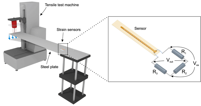
Fig. 2. (Color online) Experimental setup used for the analysis of the investigated strain sensors demonstrating the metal plate bonded to the tensile test machine and the quarter-Wheatstone-bridge circuit with a connected sensor.
Download figure:
Standard image High-resolution imageIn this study, the conventional strain gauges Kyowa KFGS-20-120-C1-11 and Kyowa KFGS-30-120-C1-11 were used to provide reference strain measurements during the calibration of the short and long sensors, respectively. In the case of the short sensors, reference strain gauges were installed on the plate aside from the investigated sensors. The long sensors had a length of over 20 cm. Such long metal foil strain gauges are not commercially available. Thus, in this study, the long sensors were calibrated based on the three conventional gauges installed on the backside of the plate, along the location corresponding to the investigated sensor installed on the top of the plate. The three conventional gauges were installed in the positions corresponding to the beginning, middle, and end of the developed sensor. During the analysis, the output signal from these three strain gauges was measured, and the average strain value was calculated. The calculated average strain was used to calibrate the developed large-scale sensor.
3. Results and discussion
3.1. Selection of materials—comparative analysis of carbon black and CNT-based sensors
This study started with the fabrication of CNT-based short sensors (2 cm), according to the procedure described in Sect. 2.1. Although in our previous work, we demonstrated the good performance of carbon black-based sensors with the hybrid (carbon black-silver) construction, 31) the CNT-based sensors were of interest because of their good mechanical properties, as reported by other researchers. 15) Thus, prior to the fabrication of large-scale sensors, the preliminary analysis with the short sensors was intended to select a functional material with regard to the strain sensitivity and linearity of the measured output signal.
To provide more information concerning the basic properties of the CNT-based sensor, the sensor with the hybrid construction was compared with a sensor that was entirely made of CNT ink. Thus, an additional sensor with no intermittent silver structure was fabricated using screen printing (Fig. 3). It had the same length and width as the intermittent pattern. The electrical resistance of such a sensor in the form of a continuous CNT line was 124.8 ± 1.6 kΩ.
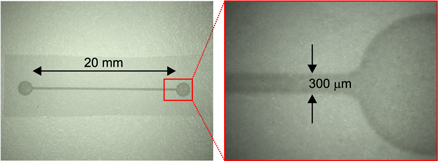
Fig. 3. (Color online) Screen-printed strain sensor entirely made of CNT ink.
Download figure:
Standard image High-resolution imageThe strain sensitivity of CNT-based sensors was analyzed by measuring the variations in the electrical resistance of the entire sensor structure when the steel plate was subjected to mechanical deformations (Fig. 2). During the analysis, 10 bending cycles up to approximately 800 microstrain (μ ε) were implemented. When the relative change in resistance was measured by the developed sensors, the reference strain measurement was simultaneously recorded by the conventional strain gauge, attached aside to the analyzed sensors. The results show that within the investigated strain range, both CNT sensors (hybrid and one entirely made of CNT) exhibit a linear output signal, no hysteresis, and almost the same strain sensitivity (Fig. 4). The observed no significant difference in the strain sensitivities shows that the sensing properties depend mainly on the functional ink used to fabricate the resistive sensing elements. This is a key feature of the sensor with an intermittent structure. Nonetheless, the calculated sensitivity (GF ≈ 0.82) was relatively low, especially when compared with the conventional strain gauges whose GF is typically approximately 2 (2.12 in this work). Next, the CNT-based sensor with the intermittent structure was compared with the previously reported sensor with the same construction, but with carbon black ink used as the functional material. 31) Figure 5 shows that the GF for the carbon black-based sensor was significantly higher (GF = 7.71) than that of the CNT-based sensor. Thus, based on the collected data, carbon black ink was selected to fabricate the resistive elements in large-scale strain sensors with an intermittent structure.
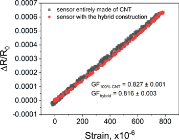
Fig. 4. (Color online) Comparative analysis of the short sensors with the hybrid (CNT–silver) construction and the sensors entirely made of CNT. The results show the recorded output signal when the sensors are subjected to 10 cycles of tensile strain.
Download figure:
Standard image High-resolution image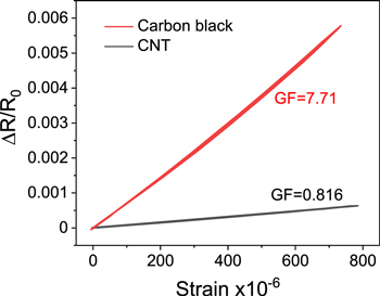
Fig. 5. (Color online) Comparative analysis of the short sensors, with the same hybrid construction, but using different materials for the sensing elements—the carbon black and CNT. The sensors were subjected to ten cycles of tensile strain.
Download figure:
Standard image High-resolution image3.2. Analysis of the large-scale sensor
The concept for the construction of the large-scale sensors shown in Fig. 6, is the same as that for the short sensors discussed in Sect. 3.1. Its construction is based on the hybrid structure of a conductive intermittent pattern with embedded resistive elements of a functional ink (carbon black in this study) that provides strain sensitivity. Thus, the resistive functional ink defines the sensor properties while the intermittent conductive patterns specify a path along which strain is measured at the points corresponding to the positions specified by the resistive sensing elements. Such a construction makes it possible to design a sensor with a desirable electrical resistance, which is especially promising for designing large-scale sensors.
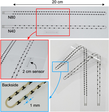
Fig. 6. (Color online) Large-scale printed strain sensors with a various number of sensing elements (N40 and N80).
Download figure:
Standard image High-resolution imageTwo types of long sensors that differed by the number of sensing elements distributed along the same sensor length were investigated (N40 and N80). For the analysis, both types of long sensors were attached to the metal plate, as shown in Fig. 2. The measurements were performed using the same data acquisition system as for the short (2 cm) sensors. First, the sensors were subjected to dynamic deformations, and the measured output signal was compared with those measured by the three reference conventional strain gauges. Figure 7 shows the data recorded for the sensor with 40 sensing elements. Both sensors (N40 and N80) exhibit similar characteristics. It can be observed that the measured output signal was very consistent with the applied external bending deformation measured by the conventional sensors. Note that the analysis was performed under bending deformations in both directions (positive and negative, alternately). It was noticed that in addition to the good response time, the measured output signal was higher than that of the conventional sensors, which indicates good strain sensitivity of the developed sensor. To determine the strain sensitivity, the collected data for both sensors (N40 and N80) were compared with the strain recorded by the conventional sensors (Fig. 8). Based on Eq. (1), the GFs of 13.26 and 13.69 for the sensors N40 and N80 were calculated, respectively. The calculated values were almost the same, which indicates that the effect of a larger number of sensing elements (and thus more contact resistance points between carbon and silver) has a very low impact on the strain sensitivity. The observed effect of more sensing elements on the increase in GF is noticeable but not significant. This finding is consistent with those of our previous studies. 31) This demonstrates that the changes in the electrical resistance of the carbon layer are the dominant factors that define the strain sensitivity of the demonstrated sensors.
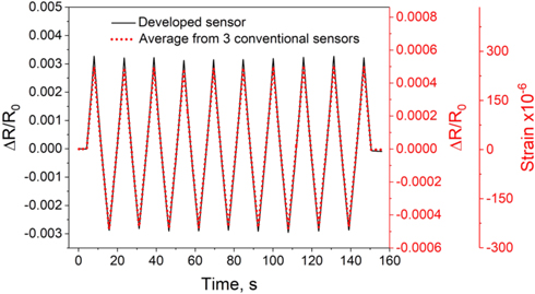
Fig. 7. (Color online) Comparative analysis of the developed large-scale sensor (N40) with the conventional strain gauges. The sensors were subjected to dynamic strain changes, in both directions, positive and negative, alternately. Thus, the sensors were subjected to tensile and compressive strains, depending on the bending direction.
Download figure:
Standard image High-resolution image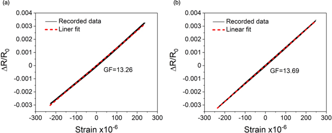
Fig. 8. (Color online) Analysis of the strain sensitivity of the large-scale sensors with (a) 40 and (b) 80 sensing elements.
Download figure:
Standard image High-resolution imageNote that the achieved strain sensitivity of the large sensors was higher than that of the short sensor (2 cm) made of the same materials. However, the strain sensitivity, besides the materials, depends on the geometry and thickness of the sensing elements. In the case of the short sensors, the sensing elements were printed using a dispenser, in the case of the long sensors, the resistive elements were screen printed. Using the dispenser, the thickness of the resistive elements was approximately 20 μm, while the screen-printed layer had a thickness of approximately 4 μm. Nonetheless, either the screen-printed sensing elements and those printed using the dispenser provide relatively high strain sensitivity, higher than those of the conventional sensors, which are sufficient for most common applications. Moreover, the sensors exhibit good linearity and no hysteresis within the analyzed strain range.
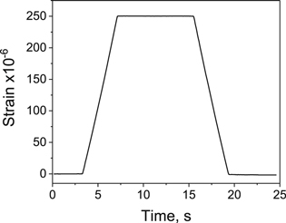
In addition to the dynamic strain analysis, the sensors were tested under static strains, as demonstrated in Fig. 9. Under static bending deformation, at the high state, the output signal remains constant and it goes back to the low state without a visible delay. In this analysis, the developed sensor was calibrated [Fig. 8(a)], that is, the measured output signal, instead of the change in resistance, shows the measured strains. For both types of sensors (N40 and N80), the collected results show good response time to the applied external deformation and strain analysis, which is consistent with those measured by the reference strain sensor. The above results demonstrate the potential suitability of the developed large-scale sensor for static and dynamic strain analyses.
Fig. 9. Analysis of the large-scale (N40) sensor under static tensile strain, showing a constant output signal at a high state. The trapezoidal profiles of the increase and decrease in strain are associated with the speed of the tensile test machine, which was set to a maximal value of 600 mm min−1 during the experiment.
Download figure:
Standard image High-resolution image
4. Conclusions
We demonstrated a new concept of large-scale strain sensors whose construction is based on a hybrid structure of a silver-based conductive intermittent pattern with embedded sensing elements made of carbon black ink. An important feature of such a sensor is the fact that the electrical resistance of the intermittent conductive pattern is much lower than the resistance of the carbon-based sensing elements. Thus, the sensitivity of the entire sensor depends almost selectively on the properties of the sensing elements. The total electrical resistance of the demonstrated large-scale sensors (20 cm) was 15.13 ± 0.79 kΩ and 31.78 ± 1.74 kΩ with 40 and 80 sensing elements, respectively. For comparison, a sensor with the same dimensions but entirely made of the same carbon black ink had a resistance that exceeded 300 kΩ. Thus, the demonstrated herein concept enables the design of a sensor with a desirable electrical resistance, which is one of the most important features of such construction.
Although further analysis with regard to temperature sensitivity, long-term durability, and the influence of the geometry and thickness of the sensing elements on the sensor properties is still necessary, the results demonstrated in this study are very promising. All sensors exhibited good strain sensitivity (GF over 13), linear output signal, and no hysteresis within the analyzed strain range. Such large-scale sensors can be especially useful for human motion detection and SHM, where large sensing systems are desirable. Nonetheless, the versatility of the printed sensors and demonstrated proper performance indicates great potential for much broader application.
Acknowledgments
This work was supported by the Fire and Disaster Management Agency in Japan.