Analysis of the Sealing Mechanism of Cement-Sodium Silicate Grout in Rock Fractures with Flowing Water
by
 and
and
Guangxuan Zhu
1, 
Qingsong Zhang
1,*,
Xin Lin
2,
Rentai Liu
1,
Lianzhen Zhang
3 and
Jianwei Zhang
4 1
Geotechnical and Structural Engineering Research Center, Shandong University, Jinan 250061, China
2
Qingdao College, Qingdao University of Technology, Qingdao 266106, China
3
College of Pipeline and Civil Engineering, China University of Petroleum (East China), Qingdao 266580, China
4
Qingdao Metro Group Co., Ltd., Qingdao 266000, China
*
Author to whom correspondence should be addressed.
Water 2020, 12(7), 1935; https://doi.org/10.3390/w12071935
Submission received: 9 June 2020
/
Revised: 1 July 2020
/
Accepted: 2 July 2020
/
Published: 7 July 2020
(This article belongs to the Special Issue Planning and Management of Hydraulic Infrastructure)
Abstract
:The diffusion and sealing mechanisms of cement-sodium silicate grout (C-S grout), which is widely used in flowing water sealing projects, are complicated. Based on a large-scale quasi-three-dimensional simulation test platform of fracture dynamic water grouting, an orthogonal experiment of flowing-water sealing of C-S grout was performed. The grout was shown to diffuse in the form of an asymmetric ellipse. The flowing-water sealing process consists of three stages: (1) the grout diffuses to the fracture boundary in an asymmetrical ellipse; (2) the solidified body of grout develops; (3) the stable solidified body forms. The sealing efficiency was evaluated and graded by the reduction of water drainage through the fracture after grouting. Based on the test data, the factors that affect sealing efficiency can be listed in the following order from strong to weak: grout gel time, flowing water velocity, grout take, fracture plane width, and fracture aperture. Finally, a fitting equation was acquired to provide a reference for practical engineering applications.
1. Introduction
In the process of underground engineering construction, gushing water is often encountered. Grouting is an effective method to treat gushing water. Because conventional cement grout does not resist the scouring of flowing water, the grout cannot be effectively retained and the desired effect cannot be achieved. Quick-setting grouting material has a short gel time and a high early strength, which can resist the scouring of flowing water, thereby effectively retaining the grout and sealing the underground water. Quick-setting grout has been widely used in underground flowing-water sealing projects.
Many studies have been performed by various researchers to understand the grouting and sealing mechanisms in a fractured rock mass. The single-fracture grouting diffusion law is the foundation of the grouting diffusion law in a fracture network. Considering cement grout as a Bingham fluid, Gustafson et al. [1] studied the cement grout diffusion law in single fractures under the conditions of one-dimensional and two-dimensional Bingham fluids. On this basis, Tion et al. [2] introduced an improved corresponding calculation model, in which the energy conservation relation of the container, crack, and intermediate state was considered. Draganović et al. [3] studied the filtration effect on grout diffusion in fractures. Influenced by the time-dependent behavior of viscosity, the grout diffusion equation in horizontal fractures was established [4,5,6].
Hassler et al. [7] used a two-dimensional fracture network model to analyze the diffusion process of grout in a rock mass. The effect of heterogeneity of the fracture aperture on the grout take was analyzed based on a plane fracture network model [8]. Eriksson et al. [9] and Rafi et al. [10] studied the effect of filtration and variation of the fracture aperture on the diffusion of grout in fracture networks. Zheng et al. [11] studied fracture deformation and the effect of interaction between parallel fractures on the grout diffusion flow field.
These studies mostly analytically calculate grouting diffusion in single fractures and fracture networks. In numerical computations, Saeidi et al. [12] used two-dimensional discrete-element software UDEC(Itasca Consulting Group, Inc. Minneapolis, MN, USA), established a numerical model of fracture network grouting, and analyzed the effect of crack opening, roughness, crack spacing, and other factors on slurry diffusion. Yang et al. [13] used the Monte Carlo method to generate a two-dimensional random fracture network and studied the seepage range and pressure distribution of cement grout in the rock mass.
The diffusion law of grout in flowing water is notably different from that in static water or without water. Li et al. [14] performed grouting tests of cement grout in a fractured rock mass, where the law of U-shaped diffusion and the mechanism of delamination and diffusion of the cement slurry under dynamic water conditions were introduced. Zhan et al. [15] regarded the grout as a Newton fluid, while the diffusion equations of dynamic water grouting under constant pressure and constant flow rate were derived. With urea formaldehyde resin and oxalic acid as raw materials, Sui et al. [16] developed a quick-setting chemical grout. The diffusion law and sealing mechanism of the chemical grout were also studied using model tests. Because of the small size of the fracture test platform in the model tests, there was a large disparity between the model test situation and the actual project, which resulted in some limitations in the test conclusions. Furthermore, chemical grouts are expensive, sometimes toxic or flammable, and require a high degree of skill for proper application [17]. The amount of slurry is very large in rock fracture sealing projects. The selection of chemical grout will increase the total cost and may pollute groundwater. Therefore, it is difficult to widely use chemical slurry, despite its excellent performance in rock fracture sealing with flowing water.
As a representative quick-setting grout, cement-sodium silicate (C-S grout) is relatively environmentally friendly and its gel time can be controlled. Moreover, it is cost-effective [18]. In China, C-S grout is the most widely used quick-setting slurry [19]. To evaluate the propagation of C-S grout in a planar fracture with static water, analytical expressions were derived by Zhang et al. considering the time-varying slurry viscosity [19]. In static water, the step-wise calculation method is proposed to describe the grouting process, considering the uneven distribution of the slurry viscosity in the grouted zone [20]. In dynamic water, the antiwashout performance of C-S grout is the key to rock fracture sealing in flowing water. Yuan et al. studied the antiwashout performance of C-S grout with flowing water in water flow channel [21]. However, there are few reports on the diffusion law and sealing mechanism of C-S grout in rock fractures with flowing water.
In this study, based on a large-scale quasi-three-dimensional fracture grouting simulation test platform, the diffusion law and sealing mechanism of C-S grout with flowing water were studied with an orthogonal experiment. The influences of the flowing water velocity, fracture aperture, fracture plane width, mixture ratio of C-S grout, and grout take on the sealing efficiency were assessed.
2. Materials and Methods
2.1. Experimental Material
In the experiment, the grouting material used was C-S grout, which is a typical quick-setting slurry. C-S grout has a much lower price than similar quick-setting chemical grouts. In addition, its gel time can be adjusted by changing the volume ratio of different solutions of cement grout and sodium silicate.
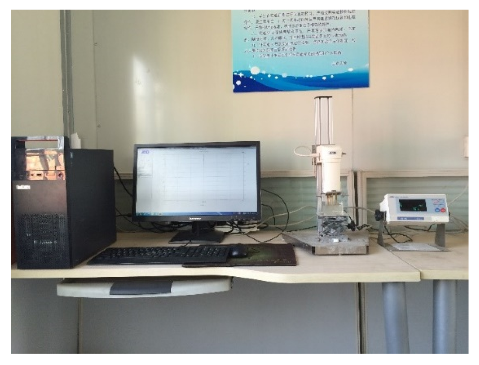
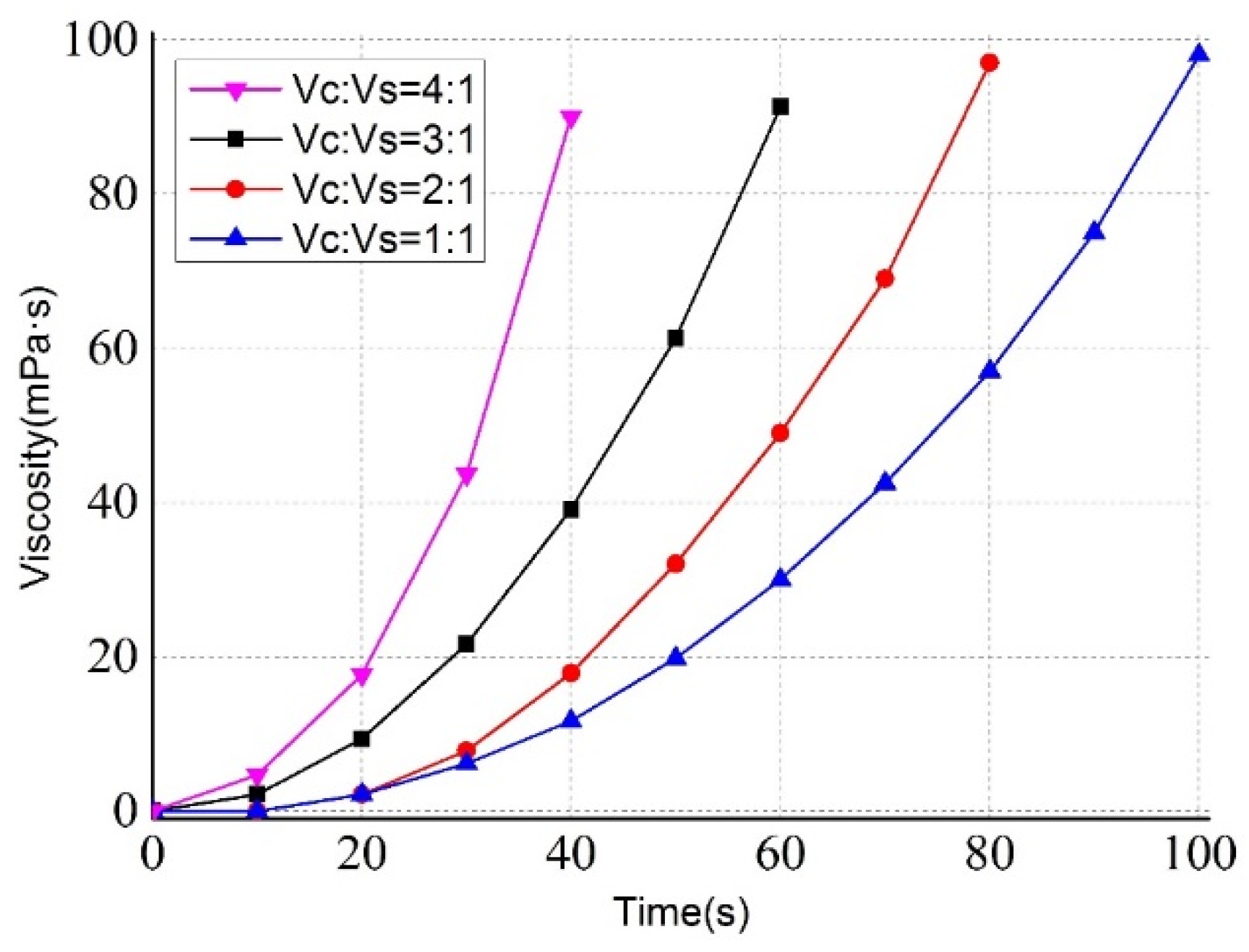
The cement in the experiment was 32.5 R ordinary Portland cement. The water/cement ratio of the cement grout was 1.0. The modulus of the sodium silicate solution was 3.0. The Baumé degree was 40. The volume ratios of the cement grout and sodium silicate solution were 1:1, 2:1, 3:1, and 4:1. The gel time of the C-S grout was measured using SV-10 and SV-100 sine wave vibration viscometers (A & D Company, Tokyo, Japan). The vibration viscometers used are depicted in Figure 1. The viscosity changes with time for different mixture ratios of C-S grout are shown in Figure 2.
2.2. Experimental Setup
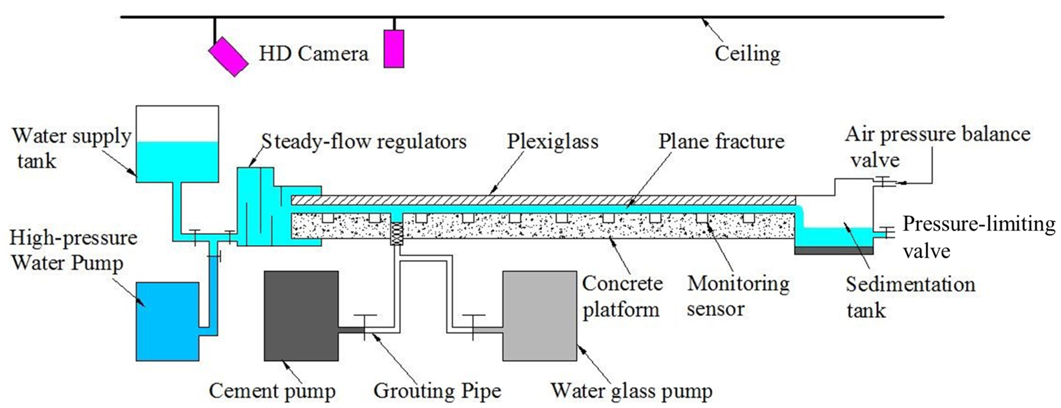
The quasi-three-dimensional fracture grouting simulation test platform developed by Shandong University was used in the experiment. The fracture grouting simulation test platform consisted of five parts: a fracture replica, a data acquisition system, a flowing water generation system, a grouting system, and a real-time video recording system. The schematic of the fracture grouting test platform is shown in Figure 3.
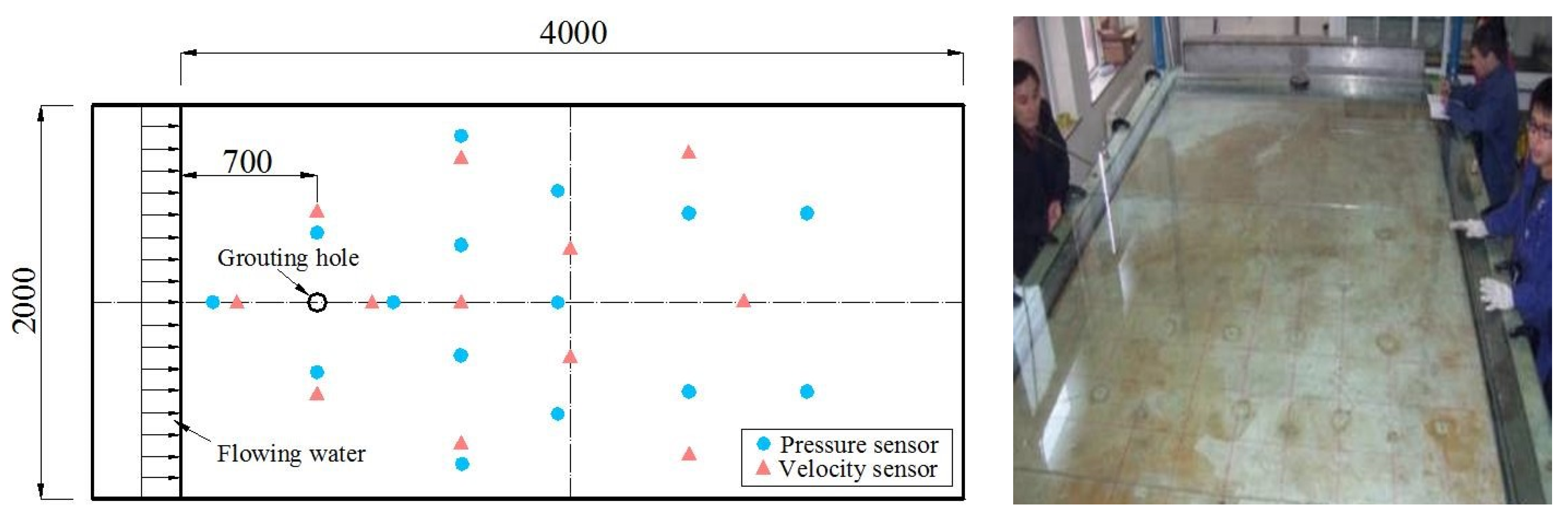
The fracture replica of the grouting test platform consisted of rock-like materials and toughened glass. The fracture replica was transparent and had a high compressive strength. The fracture replica was 4000 mm long and 2000 mm wide, with a varying aperture width of 1–30 mm according to the experimental design requirements. The width of the fracture plane could be adjusted by symmetrically changing the boundary position. The fracture plane had a varying width of 500–2000 mm. The initial velocity of flowing water could be adjusted in the range of 0–0.4 m/s. A fiber optical pressure sensor was arranged on the bottom surface of the fracture replica. A grouting hole with a diameter of 20 mm was drilled at the fracture’s bottom surface, at a distance of 700 mm from the entrance of the flowing water.
With optical fiber sensing technology, the data acquisition system can monitor and record the pressure field, velocity field, and temperature field in real time. The sensor placement is shown in Figure 4.
The cement grout and sodium silicate solution were injected by a two-shot system linked to injection pumps. The two ingredients were mixed in the mixer installed in the injection borehole. The grout rate of the two pumps was 0–50 L/min.
2.3. Design of Experiments
Affected by the groundwater condition, rock and soil factors, and grouting factors, the sealing process of flowing water grouting is notably complicated. As a result, the underground flowing water cross-section was sealed. To study the plugging mechanism of quick-setting slurry in the hydrodynamic environment, we selected the open degree of the cracks, initial crack distribution width, hydrodynamic velocity, gelling time, and grouting rate as the research variables to study the influence of various factors on the dynamic water plugging effect.
To ensure the applicability of the adjustment range of the test control variables, the blasting water inrush in a typical underground engineering fractured rock mass was investigated. According to the statistics of >300 sets of flowing water fractures, the water inflow of three ash-water-rich rock formations at >800 m in depth (Long Gu Mine, Heze City, Shandong province, China), and a marble karst aquifer at 240–400 m in depth (Zhangmatun Iron Mine, Ji’nan City, Shandong province, China), we found the following quantities:
(1) A total of 87% of fractures were >1000 mm and 32.4% were >2500 mm. These data can only show the fracture scope revealed by the roadway project and cannot fully reflect the fracture development scale. Given the feasibility of the actual test, the range of fracture widths was 1000–2500 mm;
(2) The aperture of most water-flowing fractures was 0–150 mm, of which 26% were ≤5 mm, 58.69% were ≤20 mm, and 89% were ≤30 mm. Therefore, the fracture aperture width can be adjusted between 5 and 30 mm in the experiments;
(3) Statistics for the velocity rates for flowing water in fractures at 56 sites showed that 83% were ≥5 cm/s and 17% were ≥20 cm/s. Therefore, the velocity range of flowing water in fractures was selected to be 5–20 cm/s in the experiments.
(4) In a grouting–sealing project with flowing water in a fractured rock mass, the regular mixing ratio of cement water and glass slurry commonly ranges 1:1–4:1. If the water/cement ratio of cement grout and the concentrations of the water–glass slurry vary, the gel time for the C-S grout will be different. Usually, in grouting projects, the water/cement ratio of the cement grout is 1:1 and the water–glass solution’s Baumé degree is 40. When the volume ratios of the cement slurry to water–glass are 1:1, 2:1, 3:1, and 4:1, the corresponding gel times for C-S grout are about 120, 93, 72, and 46 s.
(5) The pumping capacity of the grouting pump system in the experiments was consistent with that in the actual grouting project. Grouting was performed at a constant rate, and the grout take could be adjusted within the range of 0–50 L/min.
The grouting–sealing law of flowing water in fractures was studied based on an orthogonal test. The influencing factors and horizontal setting are given in Table 1.
3. Experimental Results and Analyses
3.1. Grout Diffusion Patterns—Asymmetric Ellipse
Based on the diffusion progress of C-S grout with flowing water, the grout diffusion traces at different moments were plotted. By analyzing and comparing the grout diffusion traces, we found two types of typical diffusion patterns. In the two typical diffusion cases, the grout traces exhibit identical laws, i.e., the diffusion paths of the slurry at arbitrary times are asymmetric ellipses that change with time. The two diffusion patterns are described in the following:
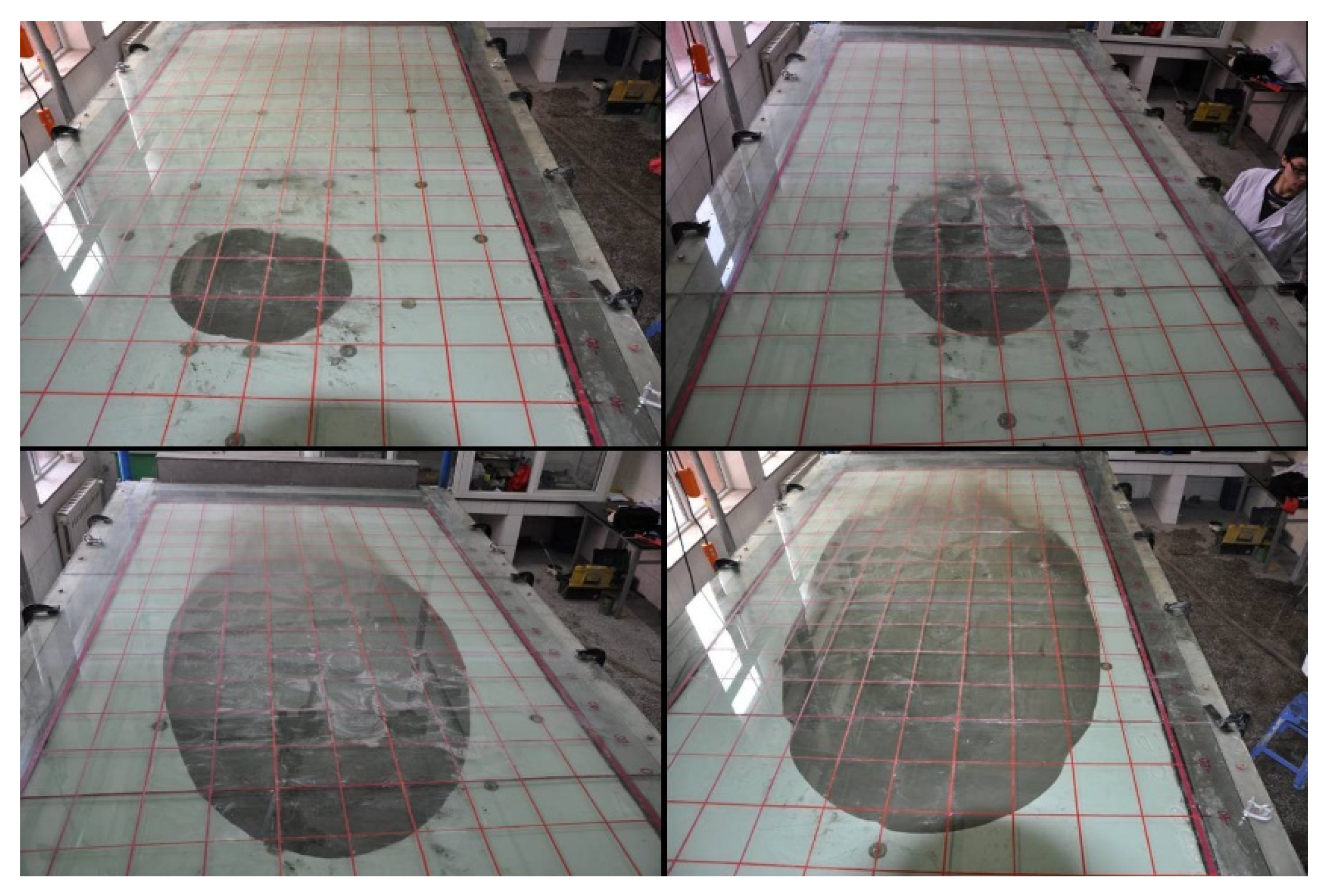
(1) The grout diffuses in an asymmetric ellipse throughout the entire process.
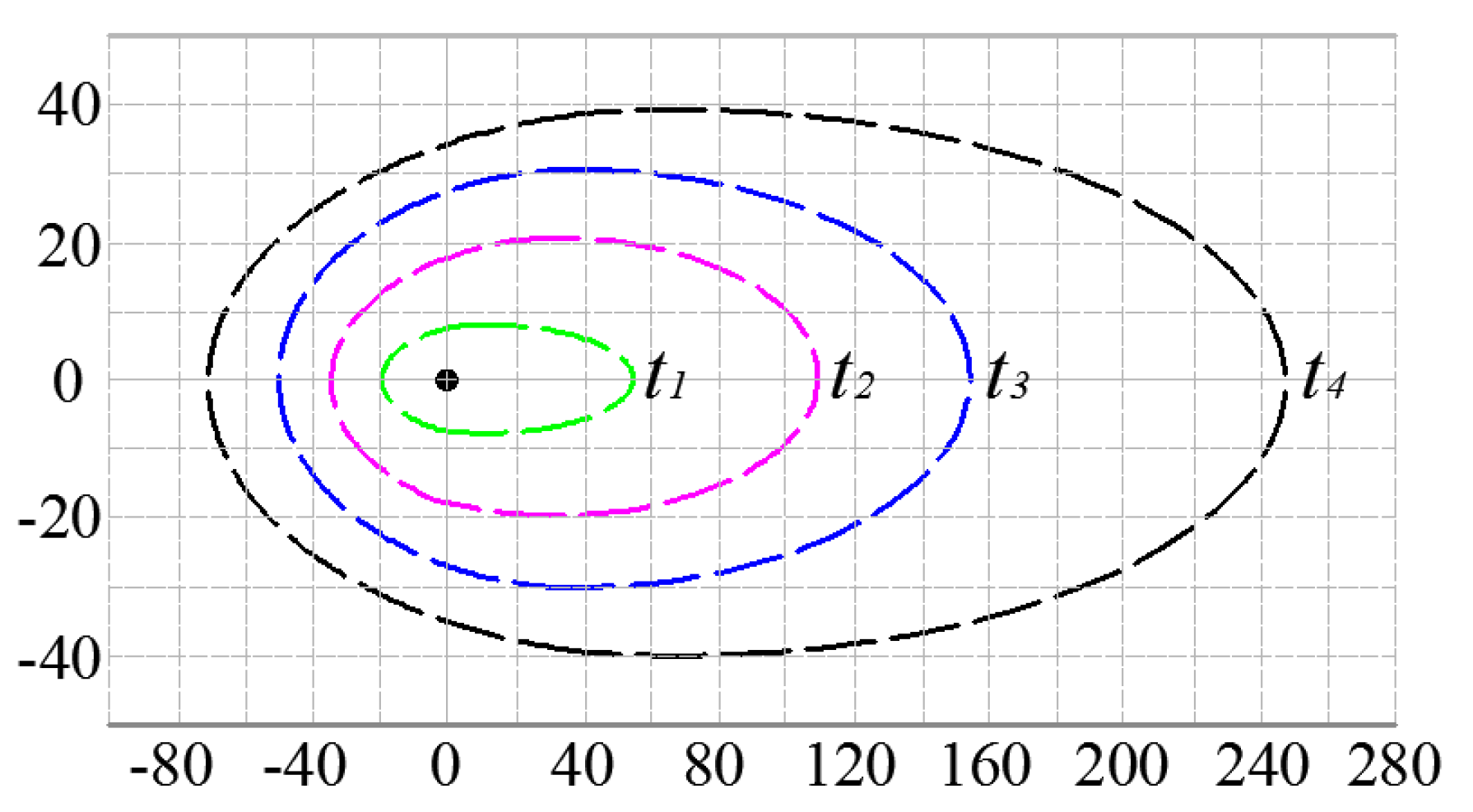
The grouting diffusion traces at representative times are depicted in Figure 5. The diffusion path lines of the grout at a representative time are sketched in Figure 6.
The grout diffusion patterns remain asymmetrically elliptical and the range expands with time. After the grout has solidified, the grout diffusion zone fails to reach the boundary of the fracture replica. The grout diffusion region is always symmetric about the x axis.
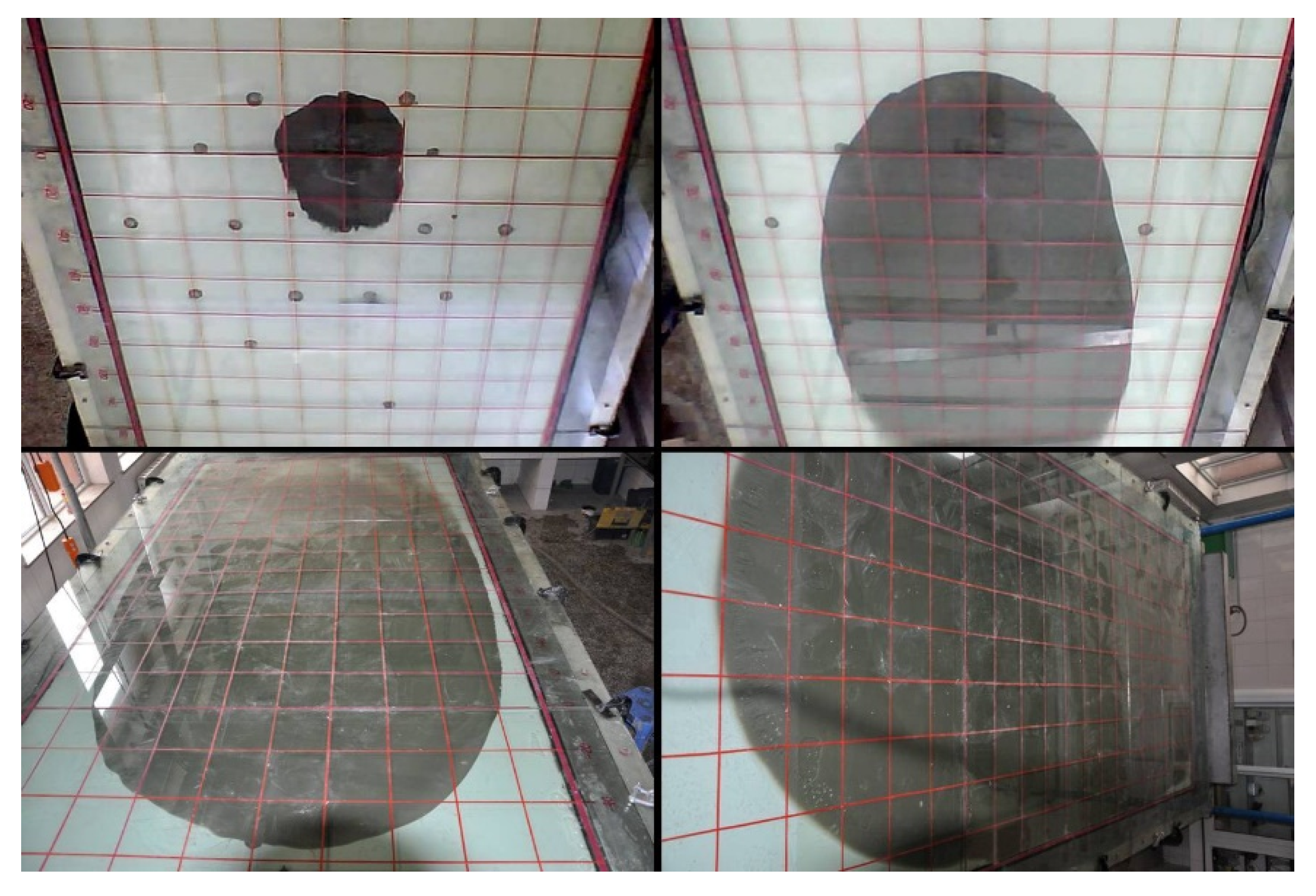
(2) The grout diffuses to the fracture boundary in an asymmetric ellipse.
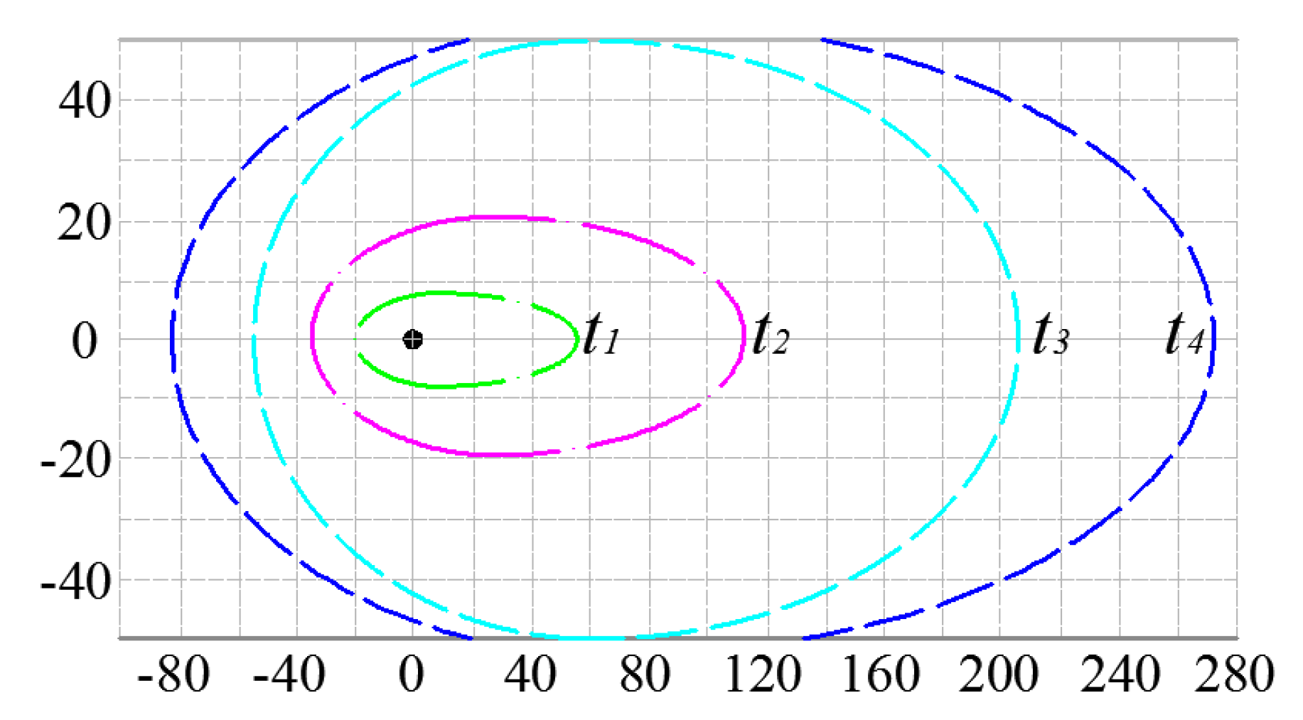
The grouting diffusion traces at representative times are depicted in Figure 7. The diffusion path lines of the grout at a representative time are sketched in Figure 8.
During the initial stage, the grout diffusion patterns remain asymmetrically elliptical and the diffusion range expands with time. At a certain time t, the grout diffusion boundary reaches the fracture boundary. At that moment, both grout diffusion traces with and against the current remain asymmetrically elliptical and the middle part of the diffusion path overlaps the boundary of the fracture replica. The grout diffusion region is always symmetric about the x axis.
In summary, the grout diffusion path lines always resemble asymmetric ellipses. The grout diffusion region should be enclosed, however it exhibits different characteristics because of the boundary of the fracture replica.
3.2. Variation of Grouting Pressure
The pressure field is one of the most important physical laws in the grout diffusion process. The variation of the grouting pressure field with different grout takes and initial velocities of the flowing water were studied with a constant fracture aperture of 5 mm. In the experiment, it is difficult to precisely control the grout take and velocity of flowing water. An error rate of <5% in the velocity of the flowing water and grout take is acceptable. The temporal and spatial variations of the fluid pressure on the x = 0 line are shown in Figure 9 (where the initial water velocity is Vw and the grout take is q).
From Figure 9, we can conclude the following:
(1) A longer grouting time corresponds to a greater grout pressure. The grout pressure declines most rapidly around the grouting hole, and the decay rate of the grouting pressure decreases with the increase in diffusion radius;
(2) A greater grout take leads to a higher grouting pressure at the same velocity of flowing water. With the increase in initial velocity of flowing water, the pressure of the slurry gradually increases if the grout take remains constant.
4. Sealing Mechanism in Fractures with Flowing Water
4.1. Three Stages of Fracture Sealing by Grouting
The grout diffuses in an asymmetric ellipse until it reaches the boundary of the fracture replica parallel to the water flow. Then, the grout diffuses into the quasi-steady state. With the solidification reaction in the diffusion process, a stable solidified body is formed and fracture sealing in flowing water is accomplished. The solidification process is as follows:
(1) The grout diffuses to the fracture boundary in an asymmetrical ellipse.
Then, it enters the quasi-steady diffusion stage, as shown in Figure 10.
At time t3, the grout diffuses to the fracture boundary parallel to the water flow. Over time, the grout diffusion zone expands. At time t6, it enters the quasi-steady diffusion stage.
(2) The solidified body of grout develops.
With time, the solidification reaction in the diffusion process proceeds, and the solidified sealing body of grout gradually forms. The grout solidified sealing body gradually expands from the periphery of the grout diffusion zone to the grouting hole, as shown in Figure 11.
(3) The stable solidified body forms.
When the slurry sealing body continues expanding, displacement no longer occurs in the slurry sealing body under the grouting pressure and groundwater pressure. When the grouting pressure increases and reaches the designed ultimate pressure, the fracture is sealed in the flowing water.
In accordance with whether the initial solidified sealing body remains in the fracture, the final diffusion form of the grout can be divided into three types, as shown in Figure 12.
The sealing of quick-setting grout in rock fractures with flowing water is always accompanied by a phase change and diffusion of the grout. According to Figure 10, the best time for fracture sealing is t3–t5. When the formation of the grout-solidified body is earlier than t3, the grout cannot diffuse to the fracture boundary parallel to the water flow, which leads to failure of the fracture sealing. When the formation of the solidified plugging body is later than t6, the grout cannot form an effective sealing body, which can result in excessive grout loss. Therefore, the effective solidification sealing body can only be formed from t3 to t5 and the sealing process shown in Figure 11 and Figure 12 will occur.
4.2. Factors Influencing Fracture Sealing with Flowing Water
4.2.1. Sealing Efficiency
It is important to select a reasonable evaluation index for the fracture sealing efficiency to study the sealing mechanism of quick-setting grout in rock fractures with flowing water. An ideal evaluation index should be able to show the plugging effect. Furthermore, it should be simple and easy to obtain. Carter et al. [22] used the decrease in hydraulic conductivity after grouting. Eriksson [23] used the decrease in drainage to evaluate the grouting quality, which is also used in this study. The sealing efficiency (SE) can be evaluated as follows:
where Q0 is the initial water flow rate prior to grouting and Qgrouted is the water flow rate after grouting, which are measured at the end of the fracture.
4.2.2. Factors Influencing Fracture Sealing with Flowing Water
Table 2 lists the orthogonal arrays of 16 experiments with 5 factors, each of which change at 4 levels, along with the SE results for each trial.
The test results were analyzed using the range analysis method and the effects of various factors on the flowing water sealing efficiency of quick-setting grout were obtained. The results of the range analysis are given in Table 3.
The orthogonal experiment and range analysis of experimental results show that the influence hierarchy (from strong to weak) on the fracture sealing efficiency is in the order of: the mixture ratio of grout, initial velocity of flowing water, grout take, fracture plane width, and fracture aperture.
The factor that has the greatest influence on the sealing efficiency is the mixture ratio of grout. Different mixing volume ratios of grouts exhibit significant differences in gelling time. Therefore, the gelling time is the most critical factor that influences fracture sealing with flowing water. These experiments gave different results from those in the study by Sui et al. [16], who showed that the gelling time of grout had a small effect on fracture sealing in flowing water. In the experiments in this work, all grouting control parameters, fracture sizes, and water inflow velocities were based on actual project statistical data, ensuring that the experimental parameters match one another and are consistent with reality.
The grout take, water flow velocity, and fracture size were much smaller than the actual engineering values in the experiments by Sui et al. [16]. Because there is not a well-developed similarity theory for grouting, it is difficult to ensure that the experimental control parameters are reasonable. Therefore, the experimental results obtained by Sui et al. [16] inevitably have some limitations.
4.2.3. SE Fitting Equation
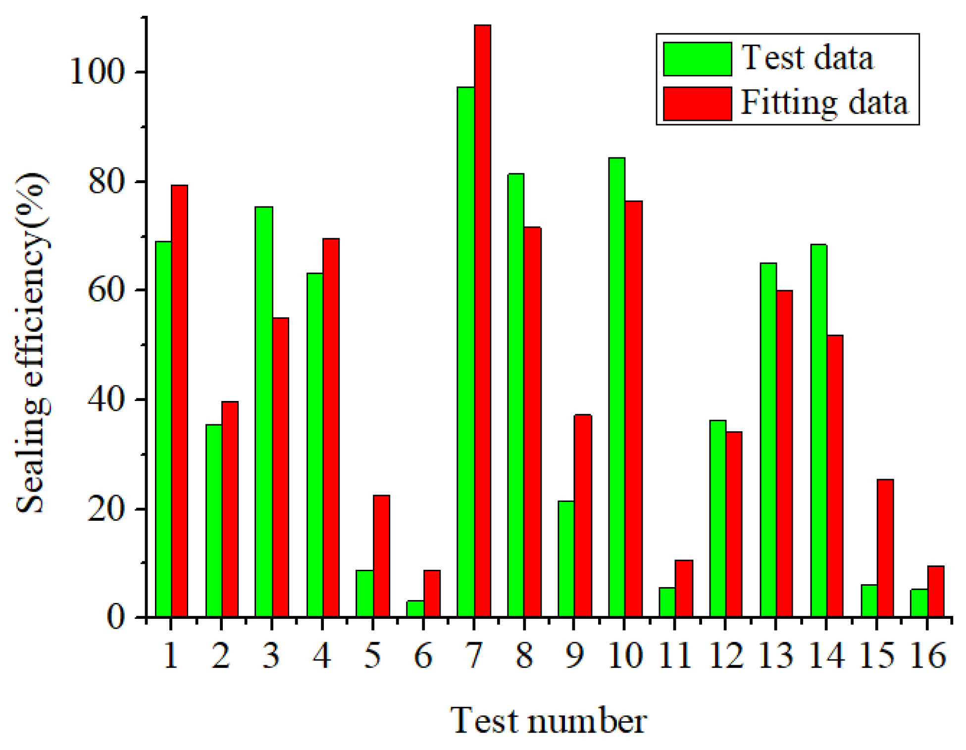
Based on the experiments above, a power law SE fitting equation was obtained through the regression analysis software Origin 9.0. The equation used to fit the experimental data can be acquired through Origin 9.0 (OriginLab Corporation, Northampton, MA, USA) automatically. The fitting equation describing the relationship between SE and the initial water flow velocity, fracture plane width, fracture aperture, mixture ratio of C-S grout, and grout take is as follows:
where SE is the sealing efficiency (in percent), W is the fracture plane width (in meters), A is the fracture aperture (in millimeters), V is the initial water flow velocity (in cm/s), M is the mixture ratio of C-S grout, and T is the grout take (in L/min). The correlation coefficient of Equation (2) was 0.912. The contrast between experimental data and fitting data are shown in Figure 13. Equation (2) could play a significant role in practical engineering.
4.2.4. Influence of Experimental Parameters
In this study, we analyzed the effects of experimental factors on the fracture sealing efficiency based on orthogonal experimental data using multiple regression analysis:
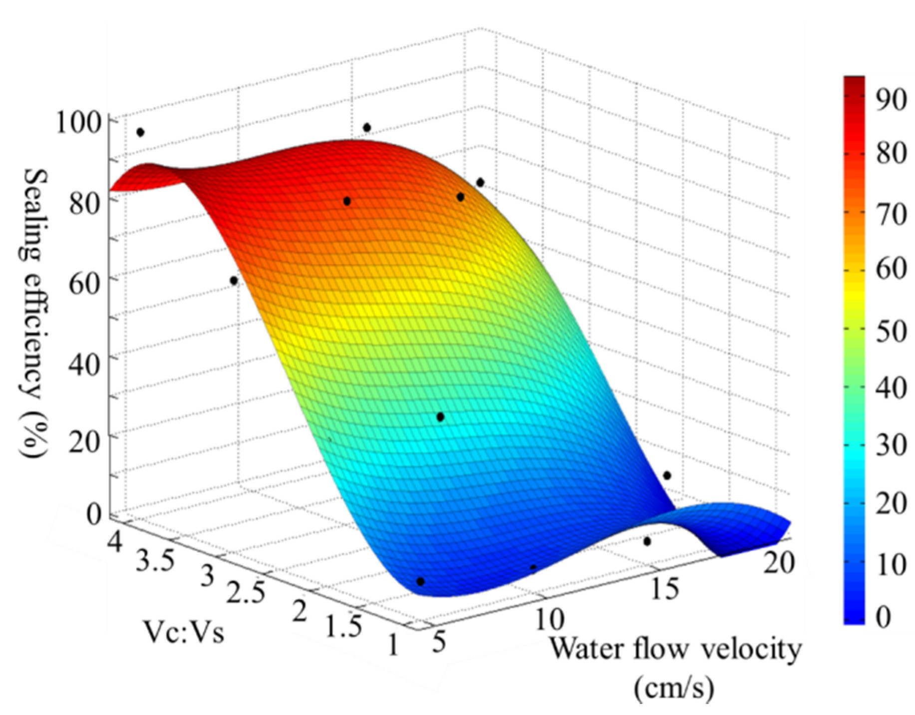
(1) Velocity of the initial water flow and mixture ratio of grout.
Figure 14 shows the fitting surface of the sealing efficiency and the effect of a combination of initial water flow velocity and the mixture ratio of grout on the sealing efficiency. Figure 14 shows that the mixture ratio of grout is the most significant factor affecting sealing efficiency. When the mixture ratio varies from 1:1 to 2:1, the sealing efficiency is <41%. With the increase in the mixing ratio, the sealing efficiency is significantly improved. When the mixture ratio reaches 4:1, the sealing efficiency is >80%. The velocity of flowing water has less effect on the sealing efficiency than the mixture ratio. In general, a higher water flow speed corresponds to a lower sealing efficiency. With the increase in the mixture ratio, the effect of the flowing water velocity on the sealing efficiency is enhanced. When the mixture ratio of grout is <2:1, the change in the water flow velocity barely affects the sealing efficiency.
When the mixture ratio of grout is 4:1, the velocity of flowing water is 5 cm/s and the sealing efficiency can exceed 85%. When the mixture ratio of grout is 4:1, the velocity of flowing water is 20 cm/s and the sealing efficiency is only 50%.
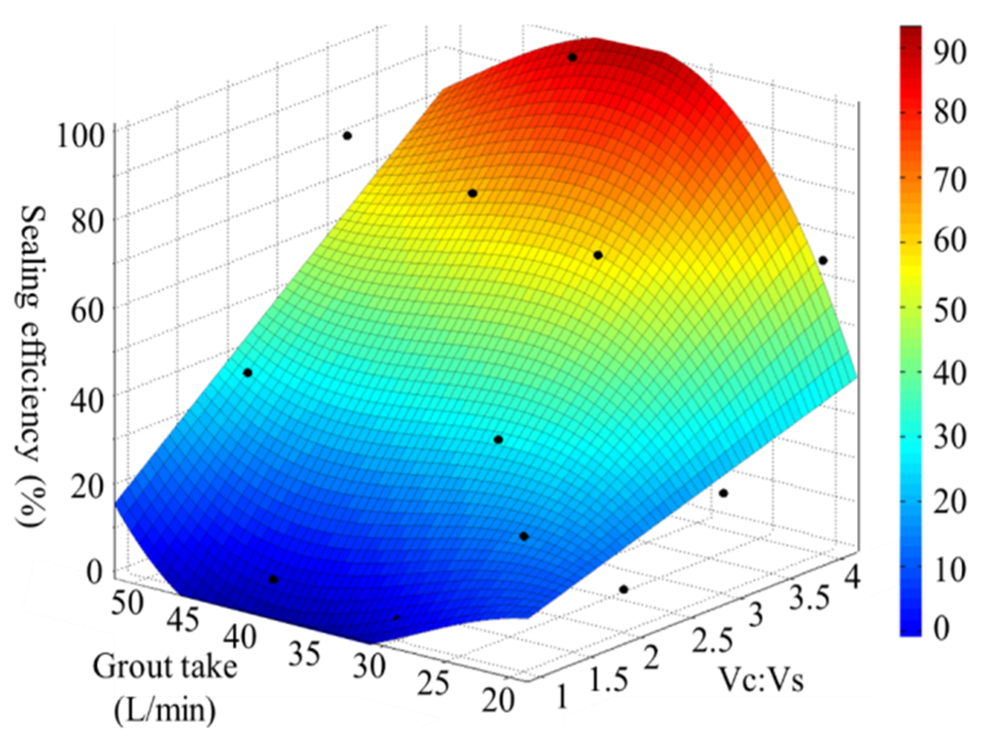
(2) Grout take
Figure 15 shows the effect of a combination of the grout take and mixture ratio of grout on the sealing efficiency. With the increase in grouting rate, the sealing efficiency is improved. In addition, a greater increase in the mixture ratio corresponds to a greater improvement of the sealing efficiency produced by the increased grout take. When the mixture ratio of grout is 1:1 or 2:1, the increase in grout take barely affects the sealing efficiency. When the mixture ratio is 4:1, the grouting rate increases from 20 to 40 L/min and the corresponding sealing efficiency increases from 40% to 90%. When the rate of grout take is further increased, the sealing efficiency slightly decreases.
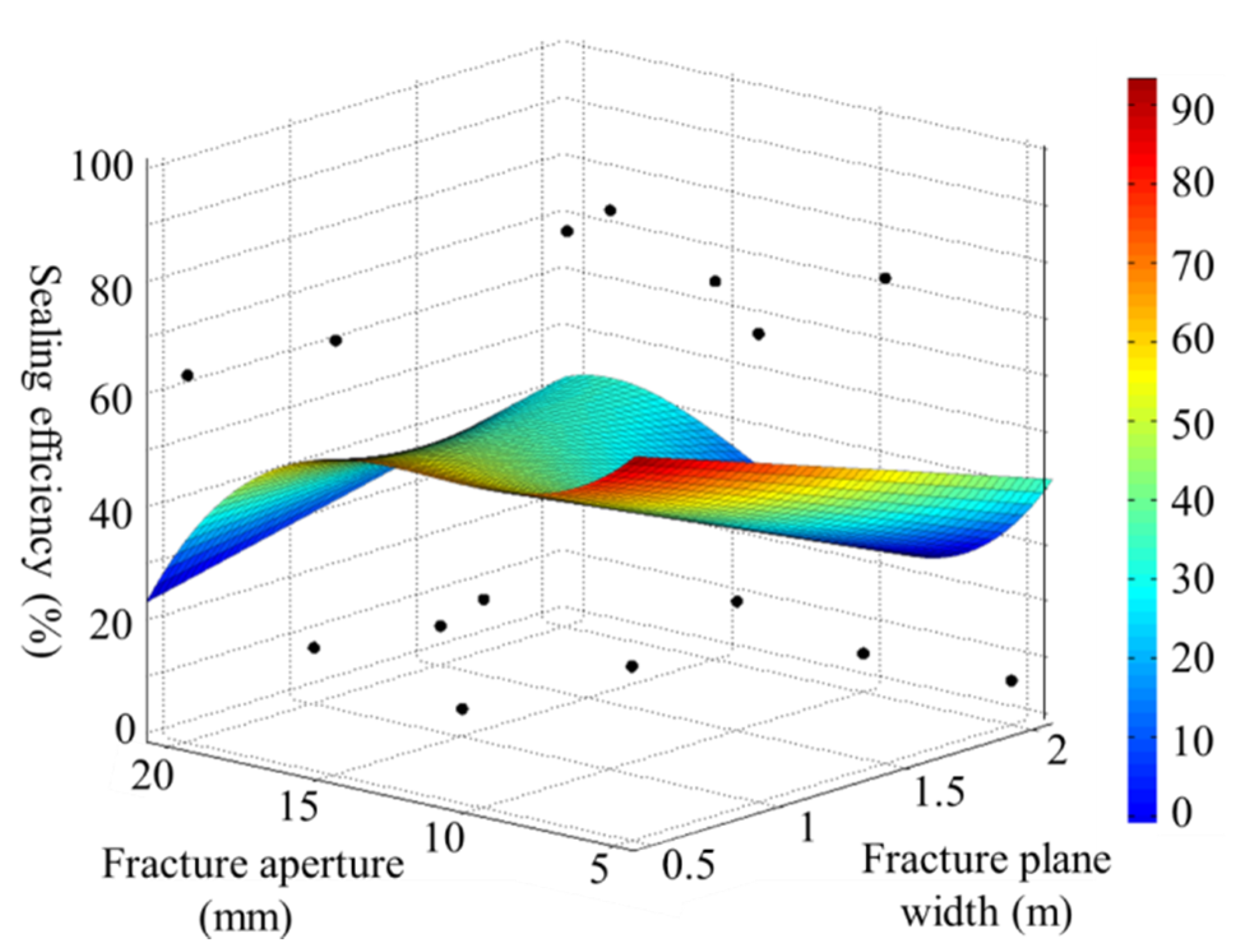
(3) Influence of the fracture plane width and fracture aperture.
Figure 16 shows that the combination of the fracture plane width and fracture aperture has a relatively minor effect on the sealing efficiency. Either a smaller fracture aperture or smaller fracture plane width correspond to a higher sealing efficiency.
5. Conclusions
Based on a large-scale quasi-three-dimensional simulation test platform of grouting with dynamic water in a fracture, an orthogonal experiment involving the plugging of flowing water with C-S grout was performed. In total, five major factors influencing the sealing efficiency were considered in the experiments: initial water flow velocity, fracture plane width, fracture aperture, mixture ratio of C-S grout, and grout take. Based on the analysis of the diffusion pattern and sealing process of quick-setting grout, the asymmetric elliptical diffusion pattern of the grout and the three stages of the fracture sealing process were obtained. The three stages of the fracture sealing process are: (1) grout diffusing to the fracture boundary in an asymmetrical ellipse; (2) a solidified body of grout developing; and (3) a stable solidified body forming.
The decrease in drainage was used to evaluate the sealing quality. The range analysis of the experimental results showed that the most significant factors that affect the sealing efficiency are the mixture ratio of C-S grout and the velocity of flowing water.
To evaluate the rock fracture sealing efficiency accurately, the calculation formula of the sealing efficiency, i.e., Equation (2), was established. In practical engineering, the initial water flow velocity, fracture plane width, and fracture aperture can be measured. Using Equation (2), the mixture ratio of the C-S grout and grout take can be adjusted to improve the sealing efficiency.
Author Contributions
Conceptualization, G.Z. and Q.Z.; methodology, Q.Z.; software, X.L.; validation, G.Z.; formal analysis, G.Z.; investigation, R.L.; data curation, X.L. and L.Z.; writing—original draft preparation, G.Z.; writing—review and editing, Q.Z., R.L. and X.L.; supervision, X.L. and J.Z.; project administration, Q.Z. and R.L.; funding acquisition, L.Z. and J.Z. All authors have read and agreed to the published version of the manuscript.
Funding
This research was funded by “National Key Research and Development Project, grant number 2016YFC0801604”, “Joint Funds of the National Natural Science Foundation of China, grant number U1706223”, “National Natural Science Foundation of China, grant number 51879152”, and “Joint Funds of the National Natural Science Foundation of China, grant number U1906229”.
Conflicts of Interest
The authors declare no conflict of interest.
References
- Gustafson, G.; Claesson, J.; Fransson, Å. Steering parameters for rock grouting. J. App. Math. 2013, 1, 1–9. [Google Scholar] [CrossRef]
- Tion Puay, H.; Hosoda, T. Mathematical modeling of the injection of grout into a horizontal slot. Int. J. Geomech. 2015, 16, 06015011. [Google Scholar] [CrossRef]
- Draganović, A.; Stille, H. Filtration of cement-based grouts measured using a long slot. Tunn. Undergr. Space Technol. 2014, 43, 101–112. [Google Scholar] [CrossRef]
- Zhang, Q.; Zhang, L.; Zhang, X.; Liu, R.; Zhu, M.; Zheng, D. Grouting diffusion in a horizontal crack considering temporal and spatial variation of viscosity. Chin. J. Rock Mechan. Eng. 2015, 34, 1198–1210. [Google Scholar]
- Ruan, W. Spreading model of grouting in rock mass fissures based on time-dependent behavior of viscosity of cement-based grouts. Chin. J. Rock Mechan. Eng. 2005, 24, 2709–2714. [Google Scholar]
- Li, S.; Liu, R.; Zhang, Q.; Sun, Z.; Zhang, X.; Zhu, M. Research on C-S grout diffusion mechanism with time-dependent behavior of viscosity. Chin. J. Rock Mechan. Eng. 2013, 32, 2415–2421. [Google Scholar]
- Hassler, L.; Hakansson, U.; Stille, H. Computer-simulated flow of grouts in jointed rock. Tunn. Undergr. Space Technol. 1992, 7, 441–446. [Google Scholar] [CrossRef]
- Gustafson, G.; Stille, H. Prediction of groutability from grout properties and hydrogeological data. Tunn. Undergr. Space Technol. 1996, 11, 325–332. [Google Scholar] [CrossRef]
- Eriksson, M.; Stille, H.; Andersson, J. Numerical calculations for prediction of grout spread with account for filtration and varying aperture. Tunn. Undergr. Space Technol. 2000, 15, 353–364. [Google Scholar] [CrossRef]
- Rafi, J.Y.; Stille, H. Control of rock jacking considering spread of grout and grouting pressure. Tunn. Undergr. Space Technol. 2014, 40, 1–15. [Google Scholar] [CrossRef]
- Zheng, Z.; Li, S.; Liu, R.; Zhu, G.; Zhang, L.; Pan, D. Analysis on grout-rock coupling effect during grouting in fractured rocks. Chin. J. Rock Mech. Eng. 2015, 34, 4054–4062. [Google Scholar]
- Saeidi, O.; Stille, H.; Torabi, S.R. Numerical and analytical analyses of the effects of different joint and grout properties on the rock mass groutability. Tunn. Undergr. Space Technol. 2013, 38, 11–25. [Google Scholar] [CrossRef]
- Yang, M.J.; Yue, Z.Q.; Lee, P.K.K.; Su, B.; Tham, L. Prediction of grout penetration in fractured rocks by numerical simulation. Can. Geotech. J. 2002, 39, 1384–1394. [Google Scholar] [CrossRef] [Green Version]
- Li, S.; Zhang, X.; Zhang, Q.; Sun, K.; Xu, Y.; Zhang, W.; Li, H.; Liu, R.; Li, P. Research on mechanism of grout diffusion of dynamic grouting and plugging method in water inrush of underground engineering. Chin. J. Rock Mechan. Eng. 2011, 30, 2377–2395. [Google Scholar]
- Zhan, K.; Sui, W.; Gao, Y. A model for grouting into single fracture with flowing water. Chin. J. Rock Soil Mechan. 2011, 32, 1659–1663, 1689. [Google Scholar]
- Sui, W.; Liu, J.; Hu, W.; Qi, J.; Zhan, K. Experimental investigation on sealing efficiency of chemical grouting in rock fracture with flowing water. Tunn. Undergr. Space Technol. 2015, 50, 239–249. [Google Scholar] [CrossRef]
- Al-Labadi, K.R.; Al-Humaidi, H.M.; Tan, F.H. Safety assessment in tunnel grouting using fuzzy rotational and angular models. J. Perform. Constr. Facil. 2009, 23, 423–431. [Google Scholar] [CrossRef]
- Zhang, D.; Fang, Q.; Lou, H. Grouting techniques for the unfavorable geological conditions of Xiang’an subsea tunnel in China. J. Rock Mech. Geotech. Eng. 2014, 6, 438–446. [Google Scholar] [CrossRef]
- Zhang, W.; Li, S.; Wei, J.; Zhang, Q.; Liu, R.; Zhang, X.; Yin, X. Grouting rock fractures with cement and sodium silicate grout. Carbonates Evaporites 2018, 33, 211–222. [Google Scholar] [CrossRef]
- Zhang, Q.; Zhang, L.; Liu, R.; Li, S.; Zhang, Q. Grouting mechanism of quick setting slurry in rock fissure with consideration of viscosity variation with space. Tunn. Undergr. Space Technol. 2017, 70, 262–273. [Google Scholar] [CrossRef]
- Yuan, J.; Chen, W.; Tan, J.; Yang, D.; Zhang, Q. New Method to Evaluate Antiwashout Performance of Grout for Preventing Water-Inrush Disasters. Int. J. Geomech. 2020, 20, 06019021. [Google Scholar] [CrossRef]
- Carter, T.G.; Dershowitz, W.; Shuttle, D.; Jefferies, M. Improved methods of design for grouting fractured rock. In Grouting and Deep Mixing 2012; Lawrence, F.J., Donald, A.B., Michael, J.B., Eds.; Geotechnical Special Publications (GSP): New Orleans, LA, USA, 2012; No. 228; pp. 1472–1483. [Google Scholar]
- Eriksson, M. Prediction of grout spread and sealing effect—A Probabilistic Approach. Ph.D. Thesis, Division of Soil and Rock Mechanics, Royal Institute of Technology, Stockholm, Sweden, May 2002. [Google Scholar]
Figure 1.
SV-100 vibrating type viscometer.

Figure 2.
Curves of viscosity change with time for different mixture ratios of cement-sodium silicate (C-S) grout.
Figure 2.
Curves of viscosity change with time for different mixture ratios of cement-sodium silicate (C-S) grout.

Figure 3.
Schematic of the fissure in the grouting model test.

Figure 4.
Fracture platform and sensor arrangement.

Figure 5.
Grouting diffusion traces at a representative time (type 1).

Figure 6.
Grouting diffusion sketch at a representative time (type 1).

Figure 7.
Grouting diffusion traces at a representative time (type 2).

Figure 8.
Sketch of grouting diffusion at a representative time (type 2).

Figure 9.
Variation of fluid pressure in the fracture replica during grouting.

Figure 10.
Schematic of the asymmetric ellipse diffusion process.

Figure 11.
Formation process of waterpower infiltration jam.

Figure 12.
Schematic of the plugging process in dynamic grouting.

Figure 13.
Contrast between experimental data and fitting data.

Figure 14.
Influence of the initial water flow velocity and the mixture ratio of grout on the sealing efficiency.
Figure 14.
Influence of the initial water flow velocity and the mixture ratio of grout on the sealing efficiency.

Figure 15.
Combined influence of the grout take and the mixture ratio of grout on sealing efficiency.
Figure 15.
Combined influence of the grout take and the mixture ratio of grout on sealing efficiency.

Figure 16.
Influence of fracture plane width and fracture aperture on sealing efficiency.


Table 1.
Test values of influencing factors used in the study.
| Factor | Level | |||
|---|---|---|---|---|
| 1 | 2 | 3 | 4 | |
| Fracture plane width (m) | 0.5 | 1 | 1.5 | 2 |
| Fracture aperture (mm) | 5 | 10 | 15 | 20 |
| Initial velocity of flowing water (cm∙s−1) | 5 | 10 | 15 | 20 |
| Volume ratio (Vc:Vs) | 1:1 | 2:1 | 3:1 | 4:1 |
| Grout take (L∙min−1) | 20 | 30 | 40 | 50 |
Table 2.
Orthogonal arrays and their results.
| Trial Number | Fracture Plane Width (m) | Fracture Aperture (mm) | Initial Velocity of Flowing Water (cm∙s−1) | Mixture Ratio of Grout (Vc:Vs) | Grout Take (L∙min−1) | Sealing Efficiency (%) |
|---|---|---|---|---|---|---|
| 1 | 0.5 | 5 | 5 | 1:1 | 20 | 69.1 |
| 2 | 0.5 | 10 | 10 | 2:1 | 30 | 35.5 |
| 3 | 0.5 | 15 | 15 | 3:1 | 40 | 75.5 |
| 4 | 0.5 | 20 | 20 | 4:1 | 50 | 63.2 |
| 5 | 1 | 20 | 15 | 2:1 | 20 | 8.9 |
| 6 | 1 | 15 | 20 | 1:1 | 30 | 3.1 |
| 7 | 1 | 10 | 5 | 4:1 | 40 | 97.3 |
| 8 | 1 | 5 | 10 | 3:1 | 50 | 81.4 |
| 9 | 1.5 | 10 | 20 | 3:1 | 20 | 21.5 |
| 10 | 1.5 | 5 | 15 | 4:1 | 30 | 84.3 |
| 11 | 1.5 | 15 | 10 | 1:1 | 40 | 5.7 |
| 12 | 1.5 | 20 | 5 | 2:1 | 50 | 36.2 |
| 13 | 2 | 15 | 10 | 4:1 | 20 | 65.1 |
| 14 | 2 | 20 | 5 | 3:1 | 30 | 68.4 |
| 15 | 2 | 5 | 20 | 2:1 | 40 | 6.2 |
| 16 | 2 | 10 | 15 | 1:1 | 50 | 5.3 |
Table 3.
Range analysis for main effects on sealing efficiency.
| Level | Average Sealing Efficiency (%) | ||||
|---|---|---|---|---|---|
| Fracture Plane Width (m) | Fracture Aperture (mm) | Initial Velocity of Flowing Water (cm∙s−1) | Mixture Ratio of Grout (Vc:Vs) | Grout Take (L∙min−1) | |
| 1 | 50.825 | 50.25 | 57.75 | 10.8 | 31.15 |
| 2 | 47.675 | 39.9 | 46.925 | 21.7 | 47.825 |
| 3 | 36.925 | 44.975 | 43.5 | 61.7 | 46.175 |
| 4 | 36.25 | 36.55 | 23.5 | 77.475 | 46.525 |
| R | 14.575 | 13.7 | 34.25 | 66.675 | 16.675 |
© 2020 by the authors. Licensee MDPI, Basel, Switzerland. This article is an open access article distributed under the terms and conditions of the Creative Commons Attribution (CC BY) license (http://creativecommons.org/licenses/by/4.0/).
Share and Cite
MDPI and ACS Style
Zhu, G.; Zhang, Q.; Lin, X.; Liu, R.; Zhang, L.; Zhang, J. Analysis of the Sealing Mechanism of Cement-Sodium Silicate Grout in Rock Fractures with Flowing Water. Water 2020, 12, 1935. https://doi.org/10.3390/w12071935
AMA Style
Zhu G, Zhang Q, Lin X, Liu R, Zhang L, Zhang J. Analysis of the Sealing Mechanism of Cement-Sodium Silicate Grout in Rock Fractures with Flowing Water. Water. 2020; 12(7):1935. https://doi.org/10.3390/w12071935
Chicago/Turabian StyleZhu, Guangxuan, Qingsong Zhang, Xin Lin, Rentai Liu, Lianzhen Zhang, and Jianwei Zhang. 2020. "Analysis of the Sealing Mechanism of Cement-Sodium Silicate Grout in Rock Fractures with Flowing Water" Water 12, no. 7: 1935. https://doi.org/10.3390/w12071935
Note that from the first issue of 2016, this journal uses article numbers instead of page numbers. See further details here.