Use Ultra-Wideband Discone Rectenna for Broadband RF Energy Harvesting Applications †
by
 , ,
, ,
Manolis G. Tampouratzis
1,* ,
,
Demosthenes Vouyioukas
1 ,
,
Dimitrios Stratakis
2 and
Traianos Yioultsis
3 1
Department of Information and Communication Systems Engineering, University of the Aegean, GR 83200 Karlovasi, Greece
2
Department of Electrical and Computer Engineering (ECE), Hellenic Mediterranean University (HMU), GR 71004 Heraklion, Greece
3
Department of Electrical and Computer Engineering (ECE), Aristotle University of Thessaloniki (AUTH), GR 54124 Thessaloniki, Greece
*
Author to whom correspondence should be addressed.
†
This paper is an extended version of our paper published in 8th International Conference on Modern Circuits and Systems Technologies (MOCAST), Thessaloniki, Greece, 13–15 May 2019.
Technologies 2020, 8(2), 21; https://doi.org/10.3390/technologies8020021
Submission received: 19 February 2020
/
Revised: 16 April 2020
/
Accepted: 20 April 2020
/
Published: 23 April 2020
(This article belongs to the Special Issue MOCAST 2019: Modern Circuits and Systems Technologies on Communications)
Abstract
:In this study, a broadband Radio Frequency (RF) energy harvester implementation is presented. The system uses a broadband discone antenna, which can operate efficiently in a broad frequency spectrum, including LTE, DCS 1800 and UMTS 2100 cellular frequency bands. The system is able to harvest energy from various electromagnetic field sources, thus has the potential to efficiently charge a storage energy element in a short time. The prototype broadband RF energy harvester was tested in the laboratory and also in a typical urban environment.
1. Introduction
Energy harvesting from radio waves is possible through devices that are called Radio Frequency Harvesters. A basic radio frequency energy harvester consists of an antenna, a matching network, a high frequency rectifier and an energy storage element. A rectenna is a rectifying antenna, a special type of receiving antenna that is used for converting electromagnetic energy into direct current (DC), and is usually found in the bibliography to describe both the antenna and the rectifier sections of a harvesting system [1]. The total power harvested from a radio frequency harvester, depends on: (a) the available power spectral density (W/m2/Hz), (b) the effective area of the antenna and (c) the operating bandwidth of the system [2,3].
The available power spectral density depends only on the electromagnetic environment. Limitations on the physical size of a RF energy harvester imposes limitations on the physical size of the antenna and hence on its effective area. The proposed antenna in [4] could be a solution for this problem. The study introduced a novel multiport rectenna system, allowing the available area for the rectenna to be fully utilized at all operating frequencies by using different numbers of antenna ports for RF energy harvesting. Measurements proved that this rectenna type could achieve output DC voltages of up to 2.2 V and DC power up to −13.6 dBm.
Thus, the most efficient way to increase the total power is by increasing the bandwidth of the system, in order to collect energy from more sources in a wider frequency range. Multiband and broadband rectennas could be a solution for increasing the bandwidth of the system, in order to collect energy from more ambient wireless sources that are distributed in a wide frequency range. Multiband rectennas normally have high conversion efficiency contrary to a narrow operating bandwidth, and can be ideal for energy harvesting from wireless communications systems, such as DCS-1800, LTE, UMTS [5].
The authors in [6] proposed a complimentary split ring resonator (CSRR) metamaterial multiband antenna with a hybrid junction ring rectifier as a multiband rectenna that was able to utilize wireless transmissions from four communication bands such as GSM, UMTS, LTE, WiFi, using separately rectifier branches. Subrectifiers have been matched by the hybrid ring junction at each operating band. With this setup, the rectenna has a peak conversion efficiency up to 67% at 1.8 GHz. Additionally, the proposed multiband rectenna was tested in an urban environment.
Broadband rectennas usually have lower conversion efficiency in contrary to a wide operating bandwidth. The design of this type of rectenna is a difficult process due to the complex matching network and the nonlinearity of the rectifiers’ diodes [5]. Tapered line matching networks could be a solution for this problem as proposed by the authors of [7] with impedance transformation from the source (50 Ω) to the load (140 Ω). The proposed broadband rectenna exhibits an improved conversion efficiency above 30% across the entire frequency range from 1.2 to 5 GHz, using an Archimedean Spiral Antenna and a wideband-tapered microstrip balance-unbalanced transmission line (BALUN).
The authors in [8] proposed a broadband rectenna using a double-sided printed monopole antenna consists of circular patch with a truncated ground plane. This type of rectenna, has an operating bandwidth range from 0.9 to 5.5 GHz and offers maximum efficiency (62.5%) with a resistive terminal load of 5 kΩ at 1.8 GHz, as shown from measurements results.
The work in [9] introduced a compact broadband rectenna using a coplanar waveguide (CPW) rectangular monopole antenna with an inverted-L open circuit stub as the matching network and a rectifying circuit based on a voltage doubler with a minimum footprint size (58 × 55 mm2). The proposed rectenna operates from 1.8 to 3.5 GHz and 5.4 to 6 Ghz, and is able to utilize transmissions from wireless applications such as GSM 1800, UMTS 2100, WLAN 802.11 a, b and g systems and also WiMAX signals efficiently up to 28% for power conversion.
Although the above systems can effectively operate in several microwave frequency bands (1 to 6 GHz), none of them is a capacitor-based RF harvester. To the best of the authors’ knowledge, the only proposed capacitor-based RF harvester is the work in [10], which can efficiently operate in the medium wave frequency band (531–1.611 KHz) using a tunable loop antenna. The system was able to harvest enough energy to charge a super capacitor to 2.8V, and sustain the voltage while no load connected to the circuit. This charge is sufficient to power a 1 kΩ load for approximately 1 h. However, in the latest system the efficiency estimation as a function of time is not mentioned.
In this work, a broadband capacitor-based RF energy harvester was fabricated consisting of a 3D discone antenna, a Dickson rectifier and a storage capacitor element for terminal load. For the total efficiency estimation of the harvesting system, we followed a methodology by enhancing the work in [11]. Our approach has taken into consideration the average power of a capacitor, which is a function of charging time and corresponds to the variation rate of its energy. The values of power density, antenna’s active surface and storage capacitor’s voltage were measured at the place of installation to determine the efficiency of the system. The prototype was tested on the laboratory and also in the urban environment. In summary, the main contributions of this study were:
- A broadband discone antenna was designed and fabricated, with efficient operation in a wide frequency spectrum to acquire ambient RF energy from many electromagnetic field sources, with excellent broadband characteristics (1.5:1 or less standing wave ratio (SWR) at a frequency range up to 10:1).
- In our work, we have introduced a novel approach of capacitor-based energy harvester’s total efficiency estimation, and its maximization at the transient state, as proven from laboratory measurements.
The rest of this article is organized as follows: the discone antenna design is presented and analyzed in Section 2. Section 3 gives a description of the Dickson rectifier basic theory and its implementation is described in Section 4. Section 5 gives a short report of the rectifier element. Section 6 is devoted to the experimental performance and measurement set-up. In Section 7, we present and analyze the efficiency estimation approach of the proposed rf harvester and finally, Section 8 gives the conclusion and a discussion on future work.
2. The Broadband Discone Antenna
The discone antenna is a version of the biconical antenna, in which one of the two cones have been replaced by a disc. A coaxial cable is usually attached at the point of intersection of the disc with the cone, to feed the antenna. The discone antenna is omni-directional, linear polarized and has a gain similar to that of a half wavelength dipole. It has excellent broadband characteristics at a frequency range up to 10:1. This type of antenna can be ideal for RF energy harvesting, besides its large size and its 3D geometry. The sensitivity of this antenna is highest in the direction of the horizon because of the narrow radiation pattern in the vertical plane. The standing wave ratio (SWR), is typically 1.5:1 or less in several octave frequencies. The behavior of this antenna as a function of frequency, is like a high-pass filter. Below the active cut-off frequency, significant standing waves appear in the feed line [12,13].
2.1. Structure Description
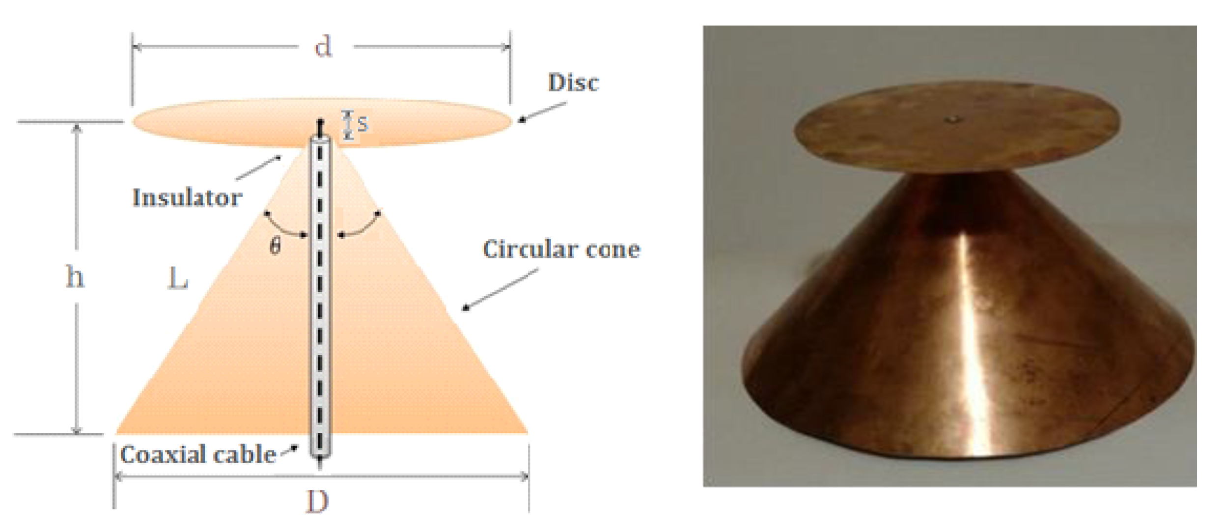
A discone antenna can be made from solid metal foil. At lower frequencies, a sufficient number of metal wires or rods are often used, thereby simplifying construction and reducing wind resistance at the same time. The rays may be made from rigid wire or welding rods. The optimal number of rods found in the bibliography, including the disc and the cone, is from 8 to 16 [14,15]. The discone antenna consists of three main components: (a) the disc, (b) the circular cone and (c) the insulator (Figure 1):
- The disc has a diameter equal to 70% of the cone diameter. The antenna’s feed point is located in the center of the disc. It is usually powered by a 50 Ω coaxial cable, with the main conductor connected to the tray and the outer conductor to the cone;
- The height of the cone must be 30% of the wavelength of the lowest operating frequency of the antenna. The inner cone angle is generally from 30 up to 100 degrees;
- The disc and the cone are separated by an insulator. The thickness of the insulator, determines some of the antenna’s properties, especially near its high frequency limits [12].
2.2. Radio Amateurs’ Construction Combinations
Different dimensional combinations of the discone antenna previously tested by radio amateurs, have demonstrated the following [16,17]:
The construction is not extremely dimensional, if 0.58D < d < 0.75D and s ≪ λ (where s is the gap between the disc and the cone). Angles from 60° to 100° represent the angle θ values range that there is a satisfactory matching for coaxial lines of 75 Ω and 50 Ω. Smaller angles, reflect better matching with an 75 Ω line, while larger angles are best adapted to the 50 Ω line. However, the gain stability and the mean gain of the antenna in the useful bandwidth seems to be inversely proportional to the inner cone angle θ.
The useful bandwidth is defined by a peak SWR ratio of 3:1, at a frequency range of 10:1. For higher frequencies the s/λ ratio increases, while the useful bandwidth is constantly decreasing. The lower operating frequency is determined by the height h. At the lower operating frequency (VSWR 3:1) h ~ 0.21λ. At this point, the gain of the antenna seems to increase as the length L (up to ~5dBi) is increased, as opposed to the useful bandwidth, which decreases. The discone antenna can be operated with a SWR ratio 2:1 at a frequency range of 4.5:1 in HF and 3:1 at the upper UHF band.
The horizontal radiation pattern (H-plane) is omnidirectional and the polarization is vertical. The gain of the antenna varies between 1.5 and 5 dBi (1.5 dBi at the frequency where L ~ 0.28λ and 5 dBi at the frequency where L ~ 0.7λ, where L is the side length of the cone). Additionally, by approaching the upper frequency limit of the useful operating range, maximum radiation occurs at small angles (3–10°) below the plane of the disc. At these frequencies, the discone antenna behaves as a conical monopole.
2.3. Discone Antenna Construction–Design Expressions
With the aid of the design equations connecting the disc dimension to the antenna cone, the prototype that is described in this study was made from 0.3-mm thick copper foil, with a cone angle of 90° (Figure 1). The height h for the antenna is 12 cm, which determines the lower cut-off frequency (in the present design corresponds to the frequency of Fmin = 750 MHz), such as the response of a high-pass filter [14]. The mathematical expression that connects the height h (in m) of the cone with the wavelength λ (in m), and consequently the cut-off frequency Fmin (MHz) of the discone antenna is h/λ = 0.3. Considering that the height h of the antenna is given by:
The disc diameter d is correlated to the diameter of the cone D, by:
A cylindrical SMA (female) type connector is attached to the top of the cone. The design that is described in this work has been based on conclusions from measurements on several structures [16], with common features: h > 0.21λ at the lowest operating frequency, 30° < θ < 100° and 0.58D < d < 0.75D as shown in Table 1. Measurements have shown that the gain of the antenna is somehow inversely proportional to its bandwidth, thus the design that is optimized for maximum bandwidth has minimum gain. In this study, maximizing the bandwidth while keeping the impedance of the antenna as possible near to 50 Ω was the main design criterion.
2.4. Antenna Simulation
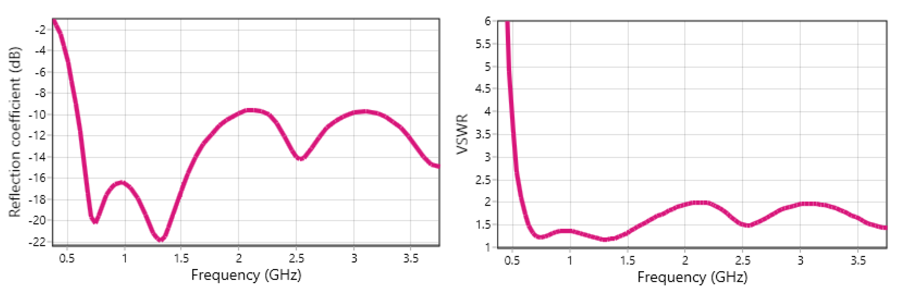
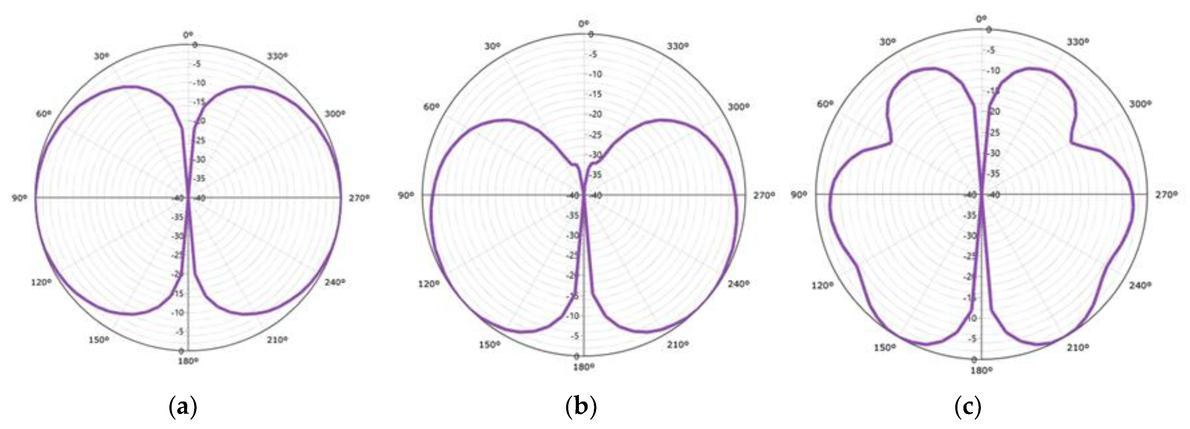
The simulation of this antenna type was carried out with Antenna Magus software, to extract the electrical characteristics and the radiation patterns in polar and cartesian form. The SWR is about 1.5:1, and the reflection coefficient (S11) ranges from −10 dB to −20 dB in a wide band of frequencies, as shown in Figure 2. Simulation results fully confirmed the theoretical lower cut-off frequency of the proposed prototype antenna as given by Equation (1). The 3D radiation charts were carried out in cooperation with CST Microwave Studio Suite software, as shown in Figure 3. Radiation patterns simulations were done at minimum (Fmin = 0.75 GHz), center (Fcent = 1.5 GHz) and maximum (Fmax = 3 GHz) operation frequencies, respectively.
3. Basic Theory of the Dickson N-Stage Rectifier
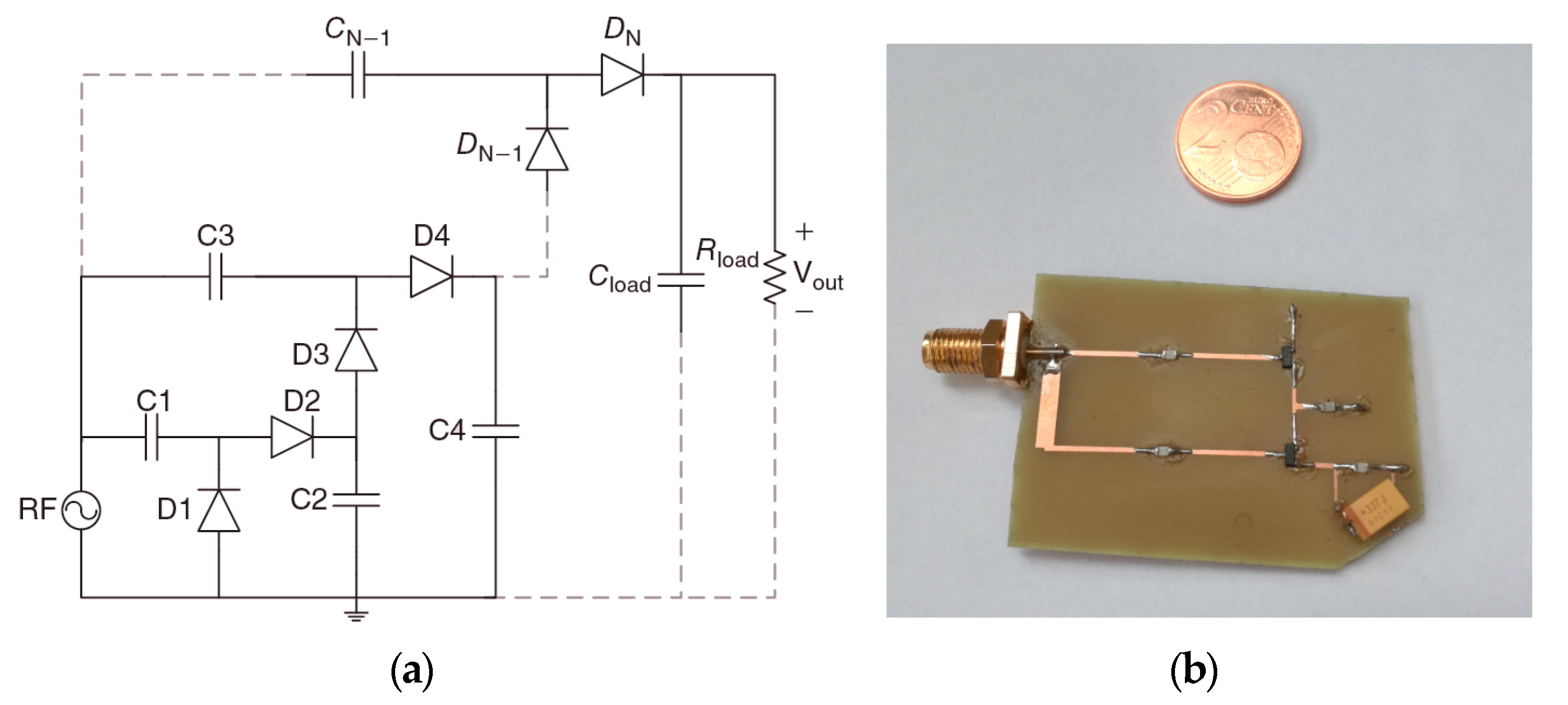
A famous RF signal rectifier topology is the Dickson rectifier with two or N-stages, as depicted in Figure 4a. The output of the circuit as a Voltage Doubler Rectifier (VDR) is given by:
where Vth1, Vth2 are threshold voltages of the diodes D1, D2 respectively and VRFin is the RF input voltage. It consists of two sections in cascade: a clamp consisting of elements C1 and D1 and a peak rectifier, consisting of C2 and D2. When the circuit is excited by a sine wave signal with amplitude Vp, the clamping section produces a waveform that positive peaks are bounded to 0, while the negative ones reach −2Vp. Taking this waveform, the peak detector segment provides, along C2, a negative DC voltage of magnitude 2Vp [18].
The individual stages of the VDR circuit can be in sequence (N steps), so as to increase the rectifier output voltage at a resistive load, which is defined as [19]:
where ILoad is the load current, C is the capacity of the blocking capacitors and fo is the operating frequency of the system. Considering the losses of the substrate, the average input power is given by the following equation:
where VT is the thermal voltage, B1 is the modified first order Bessel function, RSub and CSub are the resistance and the substrate capacity, respectively [20]. By solving (5), it is noteworthy that for a constant output voltage and power consumption, the larger the number of stages, the smaller the input voltage required to obtain a given DC output voltage and thus power consumption. However, the optimal number of stages is the trade-off between high DC output voltage and low power losses due to diode consumption and substrate losses. Experimental tests have shown that the optimum number of stages is between 1 and 2. High saturation current (ID,Sat), low crossover capacitance (CJ) for low threshold voltage Vth, small resistor in series (Rs), and finally low cross-resistance (RJ), are some characteristics of a diode for loss reduction. The HSMS series of Avago diodes are a good solution, commercially available for these applications [21,22].
4. The Rectifier Circuit Design
The rectifier design described in this study was based on a Dickson 2-Stage Rectifier; this topology is actually a voltage doubler. The specific design was studied and simulated on Agilent ADS software and was finally manufactured on a FR4 substrate with dielectric constant εr = 4.35. For the simulation of HSMS-2862 Schottky diode [23], the corresponding models from the ADS software library were used. For the passive components, general purpose models were used. The rectifier’s capacitors values were selected at 100 pF to satisfy the condition for the time constant τ, to be much greater than 10 RF cycle for the operating frequency of the circuit, which corresponds to 0.58 nsec at 1700 MHz. The storage element was connected at the rectifier’s output. The storage element is an AVX (TAJ Series) 330 μF surface mount device (SMD) tantalum capacitor, with very low equivalent series resistance (ESR) value. In series with the tantalum capacitor, a half-turn coil with low thickness (~0.6 mm) was placed, to act as a “RF choke” having an induction, approximately of 100 nH (Figure 4b).
5. The RF Rectifier Diode HSMS—2862
The basic rectifying element of the device was the AVAGO Schottky HSMS-2862 diode [23], ideal for radio frequency applications due to its features, such as low switching time, low voltage drop, short recovery time and low contact capacity. According to the manufacturer’s datasheet, this component is capable of rectifying broadband signals with operating frequencies ranging from 915 MHz to 5.8 GHz used by modern wireless communications systems, such as DCS-1800, LTE, UMTS and Wi-Fi. Indicatively, according to the datasheet, the sensitivity of the component reaches 35 mV/μW at 2.45 GHz.
6. Broadband RF Energy Harvesting at the Electromagnetic Field
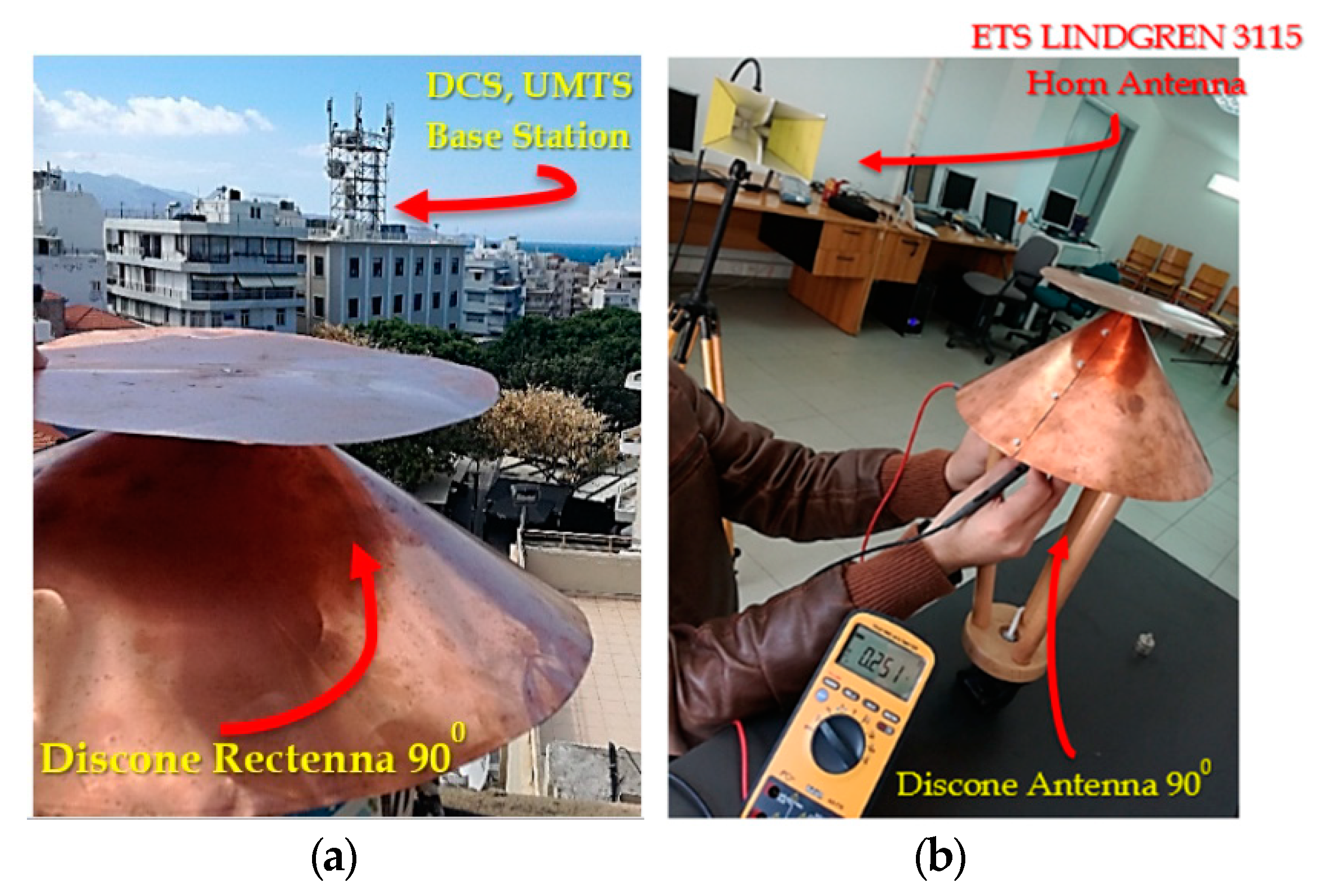
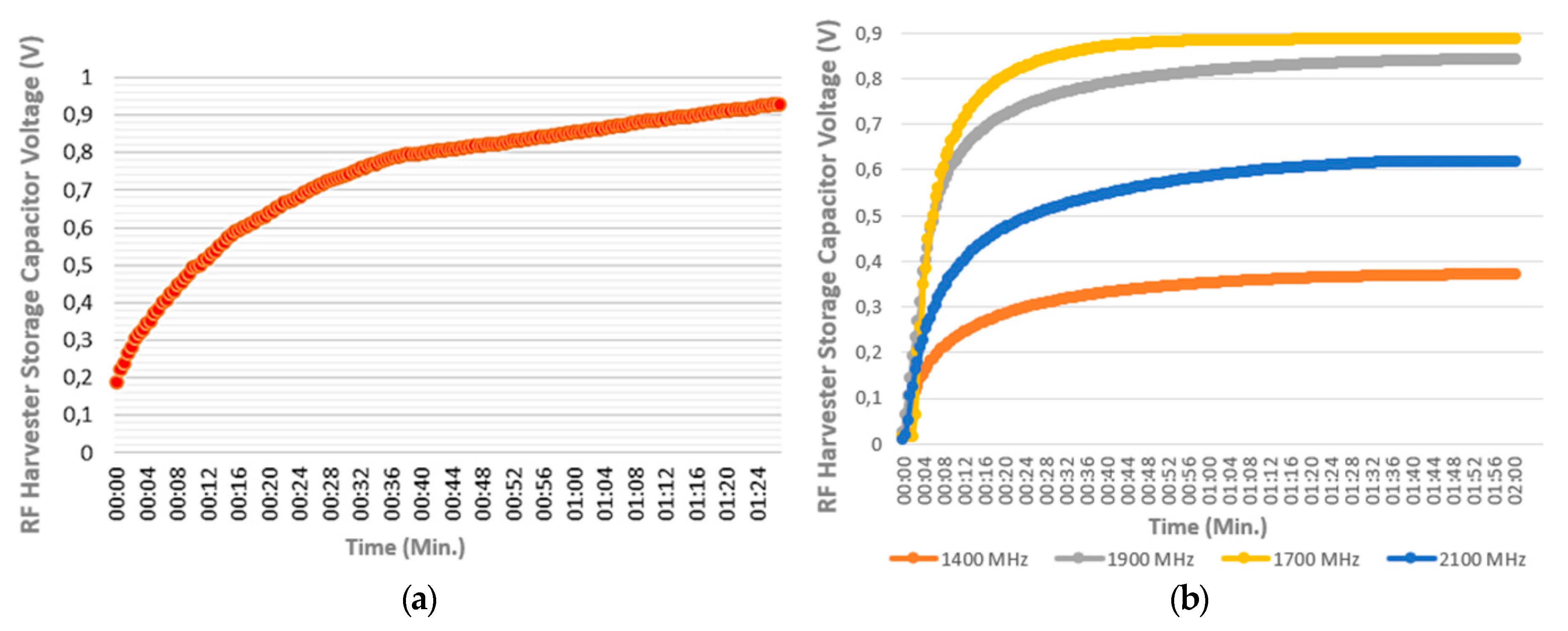
The proposed RF harvester was placed for testing at the laboratory and nearby a base station in the urban environment, with transmissions from wireless communications systems, such as DCS-1800, LTE, UMTS in the town of Heraklion, Crete, Greece. At the place of harvester installation, the broadband electric field average value (about 3 V/m) and the equivalent power density average value (about 0.023 W/m2) measured from a Narda AMS-8061/G frequency selective EMF area monitor of the EMF project [24]. The storage capacitor’s voltage at a given time t, was measured with an Axiomet AX-176 True RMS Multimeter / Datalogger. At the laboratory, the harvester was irradiated from a 3115 ETS LINDGREN Horn antenna driven by Agilent E4438C generator, for the performance evaluation of the system in several frequencies. The electric field value E and the equivalent power density average value S, were measured from a Rohde & Schwarz—FSH8 Spectrum Analyzer, at the place of harvester installation. Finally, the discone antenna’s active surface (Aeff) value was simulated and also measured approximately according to ANSI C63.5 2006 EMC standard [25,26] at the laboratory in several operating frequencies. The experiment setup is showed in Figure 5 and the measurement results (storage capacitor charging response) are presented in Figure 6, respectively.
7. Evaluation of Measurements and Applicability
From the obtained measurements, the storage capacitor’s (330 μF) maximum voltage value (Vmax) was approximately 1 V. Thus, the stored energy can be calculated according to Equation (10), and corresponds to 165 μJ. The storage element could have higher capacitance for higher energy storage in contrast to a slower charging time. To sum up, the storage capacitor’s harvested energy derived from the electromagnetic field, which was sufficient to power a load of 10 kΩ for 15 s, if we consider that:
Thus, for a 10 kΩ load and a 330 μF storage capacitor, the constant time is τ = 3.3 s. Knowing that a capacitor is completely discharged at a time of 5τ, with these component’s setup, it can be assumed that for 15 s the capacitor’s voltage will exponentially reduce to zero. For a constant time (τ = 3.3 s), the voltage will exponentially reduce due to 0.368Vmax value as described by the solution of the 1st order differential equation:
where Vc (t) is the capacitor’s voltage at time t, Vmax is the initial maximum voltage value from charging at time t = 0, C is the capacitance value and R, the terminal resistive load value, respectively.
In general, small electronic devices with minimum power consumption requirements (e.g., WSN’s node), can be powered from ambient RF Energy. The applicability of the proposed improved version of storage-based RF energy harvesting system could be the power supply of a WSN’s node for Internet of Things (IoT) applications [27]. A WSN’ node can be self-powered from ambient RF energy by the storage-based harvester when the “wake-up” mode is active (e.g., for wireless data transmission). On the contrary, at “sleep” mode of WSN’s node, the harvester’s storage capacitor will be charged from the beginning etc.
8. RF Energy Harvesting Total Efficiency Estimation Approach
The performance of a RF Energy Harvester is defined as the ratio of the power delivered to its output to the total available power in the harvester antenna. The average power of a capacitor, is a function of charging time and corresponds to the variation rate of its energy as described by (8). In this case, where the power is not constant, it is meant to refer to the energy at a given time.
8.1. Total Efficiency of Narrow Band RF Energy Harvesting Systems
Assuming that, the total efficiency of a harvesting system (α), at a given time (t), can be described by the following equation:
where Ecap (t), the harvesting energy at the storage capacitor at time (t), and ERF (t), the energy of the RF field at time (t). Knowing that, the harvesting energy at the storage capacitor at the same time (t), is given by:
where C, the capacitance value and V(t), the voltage at the storage capacitor at time (t). The RF field power is given by the following Equation:
where S is the power density (W/m2) and Aeff, is the antenna’s active surface [3]. We can claim that the energy of RF field at time (t), is given by:
The time (t) can be considered a stable quantity and extracted out of the integral. Therefore, (12), takes the form:
Thus from (9), (10) and (13) we can assume that the total efficiency (α) of a single carrier (narrow band) harvesting system, at a given time (t), can be described by:
It is worth mentioning that all quantities in the above equations are measurable, and important to determine for the efficiency of the harvesting systems.
8.2. Total Efficiency of Broadband RF Energy Harvesting Systems
We can assume that the RF energy of the operating bandwidth at time t is given by:
where f1, f2 the lower and the upper RF frequency of the operating bandwidth respectively, S the power density (W/m2), Aeff the antenna’s active surface, and (t), a given time can be considered a stable quantity and extracted out of the integral. Therefore (15), takes the form:
From (9), (10) and (16) we can claim that the total efficiency (α) of a broadband RF-EH system at a given time t, can be described by:
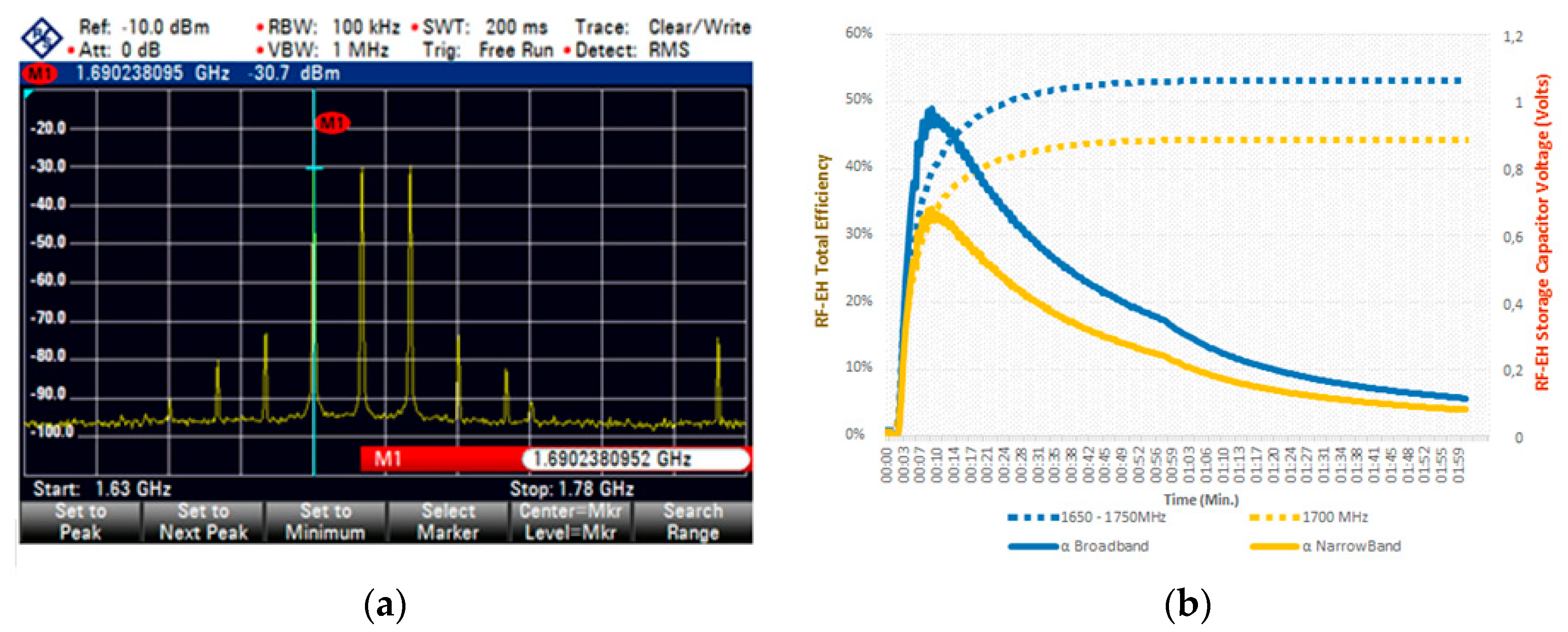
The narrowband total efficiency estimation of the system was computed according to (14) as shown in Figure 7, and the broadband total efficiency estimation of the system was computed according to (17) as shown in Figure 8, respectively.
The capacitor’s charging is a transitional process. Knowing that, from the obtained measurements it can be concluded that the storage element save energy only at the Transient state and ceases to save at Steady state.
8.3. RF-EH Storage Efficiency Maximization
Knowing that the capacitor’s voltage is a function of the charging time, that exponentially reduces to Vmax, as described by the solution of the 1st order differential equation:
where Vc(t), is the capacitor’s voltage at time t, Vmax is the maximum voltage value, C is the storage capacitor value and Reqv, is the Thevenin equivalent resistance of the Dickson rectifier in the proposed topology.
Considering (10), the storage capacitor saves maximum value of RF energy, when the variation rate of its voltage is maximized, and thus the total efficiency (a) of the system is maximized. The variation rate of storage capacitor’s voltage dVc(t)/dt, corresponds to the 1st derivative of the charging curve. Thus, the 1st derivative of Vc(t) from (18) is given by:
From (19), we can claim that the variation rate of storage capacitor’s voltage dVc(t)/dt is maximized, at the beginning of the charging (Transient state), and thus the total efficiency (α) of the system, as shown in Figure 8. When the storage capacitor’s voltage reaches its maximum value, the element ceases to save more energy (Steady state), and the average power Paver is minimized [28].
9. Conclusions and Future Aspects
This study demonstrates a broadband energy harvesting system implementation to utilize base station signals from LTE, DCS-1800 and UMTS-2100 mobile systems in the downlink frequency band, in order to charge a storage energy element (330 μF) efficiently at the urban environment in a short time (about 1 min) at 1 V. Measurements proved that a 10 kΩ load can be powered for 15 s from ambient RF harvested energy with broadband E-field average strength value of 3 V/m (0.023 W/m2 power density average value). The total efficiency a of the proposed harvester system is maximized at the beginning of the storage capacitor’s charge, as proven from measurements. Thus, a future aspect can be the construction of a pulse harvester system by switching of storage elements to utilize the efficiency maximization at the transient state, taking full advantage of inactive charging time. A prototype rectifier implementation with higher harvesting sensitivity characteristics, will be a new challenge as another future aspect. The available total harvested power can be increased by increasing the bandwidth of the system, in order to collect energy from more sources in a wider frequency range, using an ultra-wideband (UWB) antenna, such as the proposed discone antenna.
Author Contributions
Writing—original draft, M.G.T.; Writing—review & editing, D.V., D.S. and T.Y. All authors have read and agreed to the published version of the manuscript.
Funding
This research received no external funding.
Conflicts of Interest
The author declares no conflict of interest.
References
- Divakaran, S.K.; Krishna, D.D. RF energy harvesting systems: An overview and design issues. Int. J. RF Microw. Comput. Aided Eng. 2019, 29, 1–15. [Google Scholar] [CrossRef] [Green Version]
- Valenta, C.R.; Durgin, G.D. Harvesting Wireless Power: Survey of Energy-Harvester Conversion Efficiency in Far-Field, Wireless Power Transfer Systems. IEEE Microw. Mag. 2014, 15, 108–120. [Google Scholar]
- Mikeka, C.; Arai, H. Design Issues in Radio Frequency Energy Harvesting System. In Sustainable Energy Harvesting Technologies—Past, Present and Future; Intech: London, UK, 2011; pp. 236–256. [Google Scholar]
- Shen, S.; Zhang, Y.; Chiu, C.Y.; Murch, R. An Ambient RF Energy Harvesting System Where the Number of Antenna Ports Is Dependent on Frequency. IEEE Int. J. Microw. Theory Tech. 2019, 67, 9. [Google Scholar] [CrossRef]
- Song, C.; Huang, Y.; Zhou, J.; Paul Carter, P. Recent Advances in Broadband Rectennas for Wireless Power Transfer and Ambient Energy Harvesting. In Proceedings of the 11th European Conference on Antennas and Propagation (EUCAP), Paris, France, 19–24 March 2017. [Google Scholar]
- Benayad, A.; Tellache, M. A Compact Energy Harvesting Multiband Rectenna Based on Metamaterial Complementary Split Ring Resonator Antenna and Modified Hybrid Junction Ring Rectifier. Wiley Int. J. RF Microw. Comput. Aided Eng. 2019, 30, e22031. [Google Scholar] [CrossRef]
- Mansour, M.; LePolozec, X.L.; Kanaya, H. Enhanced Broadband RF Differential Rectifier Integrated with Archimedean Spiral Antenna for Wireless Energy Harvesting Applications. Sensors 2019, 19, 655. [Google Scholar] [CrossRef] [PubMed] [Green Version]
- Dardeer, O.; Elsadek, H.; Abdallah, E. Compact Broadband Rectenna for Harvesting RF Energy in WLAN and WiMAX Applications. In Proceedings of the IEEE International Conference on Innovative Trends in Computer Engineering (ITCE’2019), Aswan, Egypt, 2–4 February 2019. [Google Scholar]
- Agrawal, S.; Parihar, M.S.; Kondekar, P.N. Broadband Rectenna for Radio Frequency Energy Harvesting Application. IETE Int. J. Res. 2017, 64, 347–353. [Google Scholar] [CrossRef]
- Aminov, P.; Agrawal, J.P. RF Energy Harvesting. In Proceedings of the IEEE 64th Electronic Components & Technology Conference (ECTC), Orlando, FL, USA, 27–30 May 2014; pp. 1838–1841. [Google Scholar]
- Tampouratzis, M.G.; Vouyioukas, D.; Stratakis, D. Discone Rectenna Implementation for Broadband RF Energy Harvesting. In Proceedings of the 2019 8th International Conference on Modern Circuits and Systems Technologies (MOCAST), Thessaloniki, Greece, 13–15 May 2019; pp. 1–4. [Google Scholar]
- Kandoian, A. Three New Antenna Types and Their Applications. Proc. IRE 1946, 34, 70–75. [Google Scholar]
- Balanis, C. Antenna Theory, Analysis & Design, 3rd ed.; John Wiley & Sons: Chichester, UK, 2005; p. 521. [Google Scholar]
- Stutzman, W.; Thiele, G. Antenna Theory and Design; John Wiley & Sons: Chichester, UK, 1981; p. 243. [Google Scholar]
- Kennedy, G.; Davis, B. Electronic Communication Systems, 4th ed.; McGraw-Hill: New York, NY, USA, 1992; pp. 298–300. [Google Scholar]
- Adamidis, G. Discone Antenna Implementation. Master’s Thesis, Physics Department, Aristotle University of Thessaloniki, Thessaloniki, Greece, 2001. [Google Scholar]
- Goncalves, R.; Pinho, P.; Carvalho, N.B. Design and Implementation of a 3D Printed Discone Antenna for TV Broadcasting System. In Proceeding of the IEEE International Symposium on Antennas and Propagation & USNC/URSI National Radio Science Meeting, Vancouver, BC, Canada, 19–24 July 2015. [Google Scholar]
- Sedra, A.; Smith, K. Microelectronic Circuits, 5th ed.; Oxford University Press: Oxford, UK, 2004; pp. 189–190. [Google Scholar]
- Karthaus, U.; Fischer, M. Fully Integrated Passive UHF RFID Transponder IC with 16.7-μm Minimum RF Input Power. IEEE Int. J. Solid State Circuits 2003, 38, 1602–1608. [Google Scholar] [CrossRef]
- De Vita, A.; Lannaccone, G. Design Criteria for the RF Section of Long-Range Passive RFID Systems. In Proceedings of the Norchip Conference Proceedings, Oslo, Norway, 8–9 November 2004; pp. 107–110. [Google Scholar]
- Pavone, D.; Buonanno, A.; D’Urso, M.; Corte, F.D. Design Considerations for Radio Frequency Energy Harvesting Devices. Prog. Electromagn. Res. B 2012, 45, 19–35. [Google Scholar] [CrossRef] [Green Version]
- Buted, R.R. Zero Bias Detector Diodes for the RF/ID Market. Hewlett Pack. J. 1995, 46, 94. [Google Scholar]
- Avago Technologies HSMS-2862 Series Surface Mount Microwave Schottky Detector Diode. August 2009. Available online: https://docs.broadcom.com/doc/AV02-1388EN (accessed on 19 April 2020).
- National Observatory of Electromagnetic Fields. Greek Atomic Energy Commission. Available online: https://paratiritirioemf.eeae.gr (accessed on 19 April 2020).
- Tampouratzis, M.G. RF Energy Harvesting Circuits—Design & Implementation. Master’s Thesis, Open University of Cyprus (OUC), Nicosia, Cyprus, 2017. [Google Scholar]
- Ansi C63.5-2017 (Revision of Ansi C63.5-2005): American National Standard for Electromagnetic Compatibility—Radiated Emission Measurements in Electromagnetic Interference (emi) Control—Calibration and Qualification of Antennas (9 Khz to 40 Ghz). IEEE: Piscataway, NJ, USA, 2017. Available online: https://ieeexplore.ieee.org/document/7920447 (accessed on 19 April 2020).
- Eltresy, N.; Dardeer, O.; Al-Habal, A.; Elhariri, E.; Hassan, A.; Khattab, A.; Elsheakh, D.; Taie, S.; Mostafa, H.; Elsadek, H.A.; et al. RF Energy Harvesting IoT System for Museum Ambience Control with Deep Learning. Sensors 2019, 19, 4465. [Google Scholar] [CrossRef] [PubMed] [Green Version]
- Kushnerov, A. Transient and Steady-State Analysis of a Single Switched Capacitor Converter. Int. J. Power Electron. Drive Syst. 2019, 10, 342–350. [Google Scholar]
Figure 1.
The main parts of the discone antenna: (i) the disc, (ii) the circular cone (iii) the insulator (left) and the antenna prototype from copper foil, with an inner cone angle 90°, height 12 cm and low-cut frequency 750 MHz (right).
Figure 1.
The main parts of the discone antenna: (i) the disc, (ii) the circular cone (iii) the insulator (left) and the antenna prototype from copper foil, with an inner cone angle 90°, height 12 cm and low-cut frequency 750 MHz (right).

Figure 2.
Reflection Factor in dB (left) and standing wave ratio (SWR) versus frequency (right) of the discone antenna’s simulation results.
Figure 2.
Reflection Factor in dB (left) and standing wave ratio (SWR) versus frequency (right) of the discone antenna’s simulation results.

Figure 3.
Radiation patterns (vertical plane) of the discone antenna at (a) minimum operation frequency (left), (b) center operation frequency (center), (c) maximum operation frequency (right).
Figure 3.
Radiation patterns (vertical plane) of the discone antenna at (a) minimum operation frequency (left), (b) center operation frequency (center), (c) maximum operation frequency (right).

Figure 4.
(a) Basic topology of the Dickson N-Stage Rectifier [2], (b) The proposed rectifier circuit implementation from FR4 PCB board with dielectric constant εr = 4.35.
Figure 4.
(a) Basic topology of the Dickson N-Stage Rectifier [2], (b) The proposed rectifier circuit implementation from FR4 PCB board with dielectric constant εr = 4.35.

Figure 5.
(a) The broadband Discone rectenna experiment setup nearby a base station in the urban environment, at Heraklion, Crete, Greece and (b) testing at the N.I.R.L laboratory of the Hellenic Mediterranean University (HMU).
Figure 5.
(a) The broadband Discone rectenna experiment setup nearby a base station in the urban environment, at Heraklion, Crete, Greece and (b) testing at the N.I.R.L laboratory of the Hellenic Mediterranean University (HMU).

Figure 6.
The RF-EH’s storage capacitor (330 μF) charging response (a) from ambient broadband RF energy harvesting with equivalent power density average value 0.023 W/m2, 200 m away from base station in the urban environment, (b) testing in several frequencies at the N.I.R.L laboratory.
Figure 6.
The RF-EH’s storage capacitor (330 μF) charging response (a) from ambient broadband RF energy harvesting with equivalent power density average value 0.023 W/m2, 200 m away from base station in the urban environment, (b) testing in several frequencies at the N.I.R.L laboratory.

Figure 7.
(a) The RF-EH’s total efficiency response (a) at 1700 MHz and (b) the RF-EH’s total efficiency in several operating frequencies, tested at the laboratory. The RF-EH’s storage capacitor charging response is showen by the dashed lines, respectively.
Figure 7.
(a) The RF-EH’s total efficiency response (a) at 1700 MHz and (b) the RF-EH’s total efficiency in several operating frequencies, tested at the laboratory. The RF-EH’s storage capacitor charging response is showen by the dashed lines, respectively.

Figure 8.
(a) The broadband received RF signal (1650 MHz–1750 MHz) at Rohde & Schwarz—FSH8 Spectrum Analyzer and (b) the RF-EH’s broadband total efficiency response (a).
Figure 8.
(a) The broadband received RF signal (1650 MHz–1750 MHz) at Rohde & Schwarz—FSH8 Spectrum Analyzer and (b) the RF-EH’s broadband total efficiency response (a).


Table 1.
The Proposed Discone Antenna’s Dimensions.
| Fmin (GHz) | h (cm) | d (cm) | D (cm) | L (cm) | Θ (deg.) | S (cm) |
|---|---|---|---|---|---|---|
| 0.75 | 12 | 16 | 23 | 17 | 90 | 0.5 |
© 2020 by the authors. Licensee MDPI, Basel, Switzerland. This article is an open access article distributed under the terms and conditions of the Creative Commons Attribution (CC BY) license (http://creativecommons.org/licenses/by/4.0/).
Share and Cite
MDPI and ACS Style
Tampouratzis, M.G.; Vouyioukas, D.; Stratakis, D.; Yioultsis, T. Use Ultra-Wideband Discone Rectenna for Broadband RF Energy Harvesting Applications. Technologies 2020, 8, 21. https://doi.org/10.3390/technologies8020021
AMA Style
Tampouratzis MG, Vouyioukas D, Stratakis D, Yioultsis T. Use Ultra-Wideband Discone Rectenna for Broadband RF Energy Harvesting Applications. Technologies. 2020; 8(2):21. https://doi.org/10.3390/technologies8020021
Chicago/Turabian StyleTampouratzis, Manolis G., Demosthenes Vouyioukas, Dimitrios Stratakis, and Traianos Yioultsis. 2020. "Use Ultra-Wideband Discone Rectenna for Broadband RF Energy Harvesting Applications" Technologies 8, no. 2: 21. https://doi.org/10.3390/technologies8020021
Note that from the first issue of 2016, this journal uses article numbers instead of page numbers. See further details here.