
mmWave Beam Tracking for V2I Communication Systems Based on Spectrum Environment Awareness

1
The Key Laboratory of Dynamic Cognitive System of Electromagnetic Spectrum Space, College of Astronautics, Nanjing University of Aeronautics and Astronautics, Nanjing 211106, China
2
The Key Laboratory of Dynamic Cognitive System of Electromagnetic Spectrum Space, College of Electronic and Information Engineering, Nanjing University of Aeronautics and Astronautics, Nanjing 211106, China
*
Author to whom correspondence should be addressed.
Symmetry 2022, 14(4), 677; https://doi.org/10.3390/sym14040677
Submission received: 16 February 2022
/
Revised: 23 March 2022
/
Accepted: 23 March 2022
/
Published: 24 March 2022
(This article belongs to the Section Computer)
Abstract
:Real-time matching of millimeter wave (mmWave) narrow beams is a great challenge in dynamic vehicle to infrastructure (V2I) environments due to the mobility of vehicles. In this paper, a novel beam search strategy based on spectrum-environment awareness is proposed. Combining the technique of label iterative optimization with three-dimensional (3D) grid encoding, the strategy treats the optimal beam pair indexes (BPIs) as labels and encodes the environments as features. Three-dimensional grid encoding is a symmetry-based environmental coding technology. A new Convolutional Neural Network (CNN) model is also constructed, which is trained by the features. The situational beam search of actual vehicles is performed under the trained CNN model. As a result, real-time mmWave narrow beam matching can be achieved. Simulation results demonstrate that the proposed strategy can effectively reduce the beam search overhead and improve the efficiency while guaranteeing the matching accuracy.
1. Introduction
In recent years, with the dramatic growth of vehicles, a growing number of vehicles access the network, increasing the demands on telematic latency, computing power, data volume, system sum-capacity and total energy efficiency [1]. It is necessary to improve data rates and widen signal transmission bandwidths [2,3]. Conventional non-orthogonal multiple access (NOMA) promises to meet the resource-intensive demands of the future internet of vehicles (IOV) [4,5]. Currently, millimeter wave (mmWave) communication with an ultra-high transmission rate is considered for internet of vehicle networks to meet the high throughput and time delay requirements [6,7]. However, the high frequency nature of mmWave leads to severe path losses when signals transmit [8]. Multiple antenna technology is an effective method that can be used to generate directional narrow beams to solve this problem. Nevertheless, due to the mobility of vehicles and the interaction between them [9], it is difficult to align narrow beams in real time, which affects the communication quality.
Beam search is a widely used method to match mmWave beams. Traditional beam search methods use an exhaustive search to match all beams at the transmitter and the receiver one by one to obtain the optimal beam pair. These methods are computationally intensive and they only consider the current state of scenarios. IEEE 802. 15. 3c [10] and IEEE 802. 11. ad standards optimize the beam search process. They reduce the number of operations by separating the search process into a sector-level search [11] and beam-level search [12]. However, the complexity of these methods increases with the number of codebook dimensions. One approach to solving this problem is a hierarchical search [13]. This approach searches multiple beams by using a pre-designed analog hierarchical codebook, and the pre-designed codebook has an oversampling layer to guarantee the estimation accuracy of the beam direction. However, the high vehicle mobility and short beam coherence time in vehicular communications lead to great difficulties in the implementation of these methods. By combining vehicle traffic simulators with Ray Tracing (RT) to generate channel state parameters for 5th Generation (5G) mmWave massive multiple-input multiple-output (MIMO) communications, Klautau A et al. simplified the process of creating data in complex mobile scenarios [14]. They also used a deep learning approach to realize the beam selection. Nevertheless, this method does not encode environmental characteristics and ignores possible environmental impacts in the actual implementation.
The ignorance of environmental factors in IOV scenarios makes it difficult to achieve real-time alignment of narrow mmWave beams. A number of works have shown that this problem can be overcome by using edge-information-assisted mmWave beam training methods [15,16,17,18]. The methods use information from sensors (such as radar) as auxiliary information for mmWave communication link configuration. The sensors can be connected to share their observations while having the ability to learn [19,20]. These methods can achieve fast alignment of the initial beam, but the mobility of the vehicle and the characteristics of the narrow beam also make the beams difficult to align in real time [21]. Vutha Va et al. quantified the receiver position as pixels, implemented beam training through machine learning of the position features, and recommended possible beam pairs by combining statistical learning methods [22]. They also proposed a method, Learning to Rank (LtR), which uses location information and past beam measurements to narrow the beam training to a restricted area [23]. However, these method only consider the relevant location of the target vehicle. Other information, such as the influence of other vehicles, is ignored.
There have been extensive works on beam alignment for simulation studies in different environments. A deep learning neural network for classification was proposed by Sajad Rezaie et al. [24] to perform a beam search. The neural network takes the receiver location and incoming wave direction as the input and takes the probability of each beam pair becoming the best beam pair as the output. It trains the model along the path direction of the best power to recommend a candidate list of the best beam pairs. However, the method only considers indoor scenarios, which are different from those in the case of IOV communication. Imtiaz Nasim et al. [25] considered a multi-vehicle interference management mechanism, which formulates the beam selection problem to a combinatorial multi-armed bandit (CMAB) pattern. This pattern can not only accurately estimate the optimal beam pair for multiple users simultaneously in a multi-vehicle environment, but also identify and adapt to the changes in vehicle environments. Yusuke Koda et al. [26] proposed a feasible system for tracking directional beams using historical values of the position and the velocity with an on-wire mmWave node. They leveraged deep reinforcement learning (DRL) to determine beam steering angles based on past position/velocity information of a mmWave node. This method is expected to shed light on mmWave node deployments in unstable environments. However, the adaptive beam tracking schemes proposed in [25,26] only consider the position and the size of the target terminal, ignoring the possible effects of the height.
To fill the gaps mentioned above, in this paper we propose a Convolutional Neural Network (CNN) -based beam search method. The major contributions and innovations of this paper are summarized as follows:
- (1)
- Considering the environment, vehicular motion and vehicular characteristics, a novel CNN-based beam search strategy is proposed. The strategy takes into account a crowded urban environment and the state of moving vehicles. As a result, the tradeoff between the generality and practicability is achieved, which maximizes beam search efficiency while guaranteeing the accuracy. Meanwhile, the strategy saves the system power by eliminating the requirement for real-time beam training.
- (2)
- A symmetry-based three-dimensional (3D) grid coding method is developed to optimize the CNN model establishment. The method simultaneously considers the vehicular positions, height, lanes and other information to encode the transmission scene, and provides a coding characteristic matrix with the characteristics of the four-dimensional tensor. The method expands the feature space to fully exploit the environmental information, and thus, contributes greatly to the improvement of beam search accuracy.
- (3)
- A CNN-based labels iterative optimization is developed to improve the accuracy of the proposed beam search method. It applies the label data of known scenes to train the model, so that, the optimal beam pairs for unknown scenes can be predicted, further improving the beam search accuracy.
The rest of the paper is organized as follows: Section 2 introduces the urban two-lane scenarios and channel models. Section 3 presents the 3D grid encoding method and the specifics of label iteration optimization. The simulation and tested results are provided in Section 4. The conclusions are drawn in Section 5.
2. Channel Model and Problem Formulation
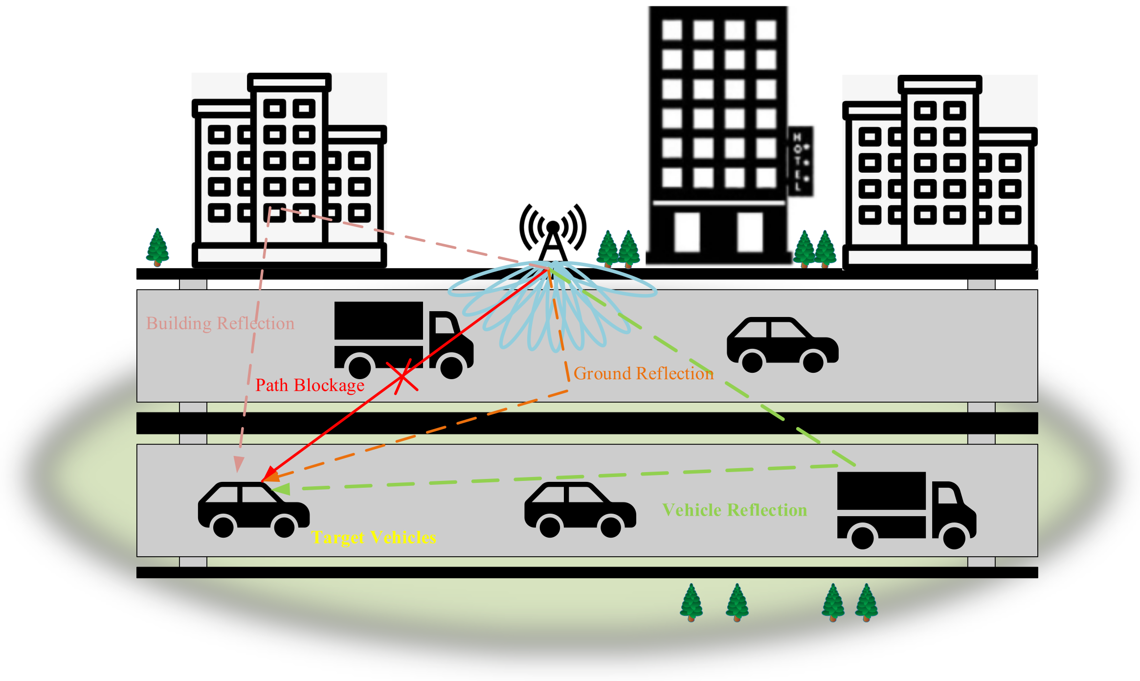
Let us consider a typical vehicle to infrastructure (V2I) communication scenario as shown in Figure 1, where the base stations (BSs) with low heights are deployed on both sides of the urban road and the vehicles, consisting of small cars and large trucks, are randomly distributed. The line of sight (LOS) path from the vehicle to the BS may be obscured due to the presence of a large number of vehicles with different sizes and motion states [27]. In addition, various objects distributed on both sides of urban roads can reflect electromagnetic waves, forming none-LOS paths (NLOSs). We treat ground buildings or other roadside structures as static reflectors, and vehicles, moving bicycles and the moving crowd on the road as mobile reflectors [28]. In this paper, we do not consider the effects of bicycles and the crowd with low heights or marginal locations. The location, size and type of vehicles can be tracked by the sensors.
For the BSs with low heights, the vehicles are the main contributors to block the signal propagation. Since antennas are typically placed on top of vehicles, the location and the size of vehicle can determine the direction and intensity of the beam.
In this paper, a two-lane scenario is built. Considering the symmetry relationship between the two-lane scenario and the simulation parameters, a ray-tracing simulator is used to collect data and create a database. Buildings on both sides of roads are modeled as cubes made of concrete and with random sizes. Two types of vehicles are mainly considered, namely cars and trucks, both of which are modeled as rectangular bodies with metal shells and obey random distribution over the lanes. The length of the street is set to approximately 200 m. Due to the high height of the truck, no path blockage occurs when the receiver is deployed on top of the truck, and machine learning is not required for prediction during beam searching. Therefore, our searching strategy is only designed for the cars with low-height receivers.
When searching beams, a ray-tracing simulator is used to calculate the strongest paths [29] between the transmitter and the receiver. Based on the strongest path information output from the ray-tracing simulator, a received signal model including channel and beam information can be constructed. Based on the model, the best beam pair can be obtained by comparing the received power.
On account of the communication scenario mentioned above, the channel model can be expressed as:
where is the number of antennas for the transmitter, is the number of antennas for the receiver, and is the path gain of the l-th path, and are the antenna array response of the receiver and transmitter, respectively, where and denote the arrival azimuth and elevation angles of the l-th path, and and are the departure azimuth and elevation angles of the l-th path.
Since mmWave V2I communication requires dense deployment of BSs and short distances between the BSs and vehicles, the channel is susceptible due to variations of vehicle height and elevation angle extensions [30]. To reduce the possible impact on the channel, uniform planar arrays (UPA) are used at both the transmitter and receiver. The antenna array of the transmitter is oriented towards the street and the antenna of the receiver is deployed on the top of the car facing upward. Let , , and be the wave number, then, the steering vector can be expressed as:
where and are the numbers of elements along two coordinates of the x-axis and y-axis, and are defined by the distance between the horizontally contiguous elements and vertically contiguous elements, respectively, and ⊗ denotes Kronecker product and we make .
The two-dimensional (2D) Discrete Fourier Transform (DFT) codebooks are used at both the transmitter and the receiver, which are expressed as and , respectively. We take in our work and the i-th beam vector in and is . The 2D DFT can be represented as:
where , . We make:
We columnize G as , F as . The vector g and f constitute the DFT-based beamforming codebooks C, which makes . Therefore, this 2D DFT-based beamforming weight-vector can be expressed as:
where k corresponds to the k-th element of vector f, which is the u-th row and v-th column of matrix F, and j corresponds to the j-th element of vector g, which is the x-th row and y-th column of matrix G. Therefore, we have and . If the beam codebook is designed adaptively according to the actual scene, satisfactory performance can be obtained.
A beam pair can be converted into a unique corresponding beam pair index , where . For the i-th beam pair, its effective channel [22] can be given by:
Based on (2), the optimal beam pair index (BPI) can be expressed as:
3. V2I Beam Tracking Using Deep Learning
In this section, a V2I mmWave beam training scenario is established. We encode the environment, iteratively optimize the data labels, and combine the CNN algorithm to achieve the optimization of the beam search.
When the target vehicle enters the coverage area of BS, it automatically detects the network and connects to the BS. During this process, basic information about vehicles, such as the manufacturer and model, is transmitted to the BS. Such information can help the BS to determine the size and type of the vehicles used to encode the environmental characteristics. At the same time, the vehicles send a request to the BS to start the beam training, and the BS performs beam searching among the target vehicles to find the optimal beam pair. Due to the mobility of vehicles, the BS receives the location update information regularly from the target vehicle to keep the position tracking. After obtaining the information of all vehicles, we can develop a vehicle situational awareness map and store the map as a feature in the BS database. The optimal beam pair index for each data sample is defined as a classified label in order to facilitate the subsequent optimal beam matching of the actual vehicle.
3.1. Environmental Feature Coding
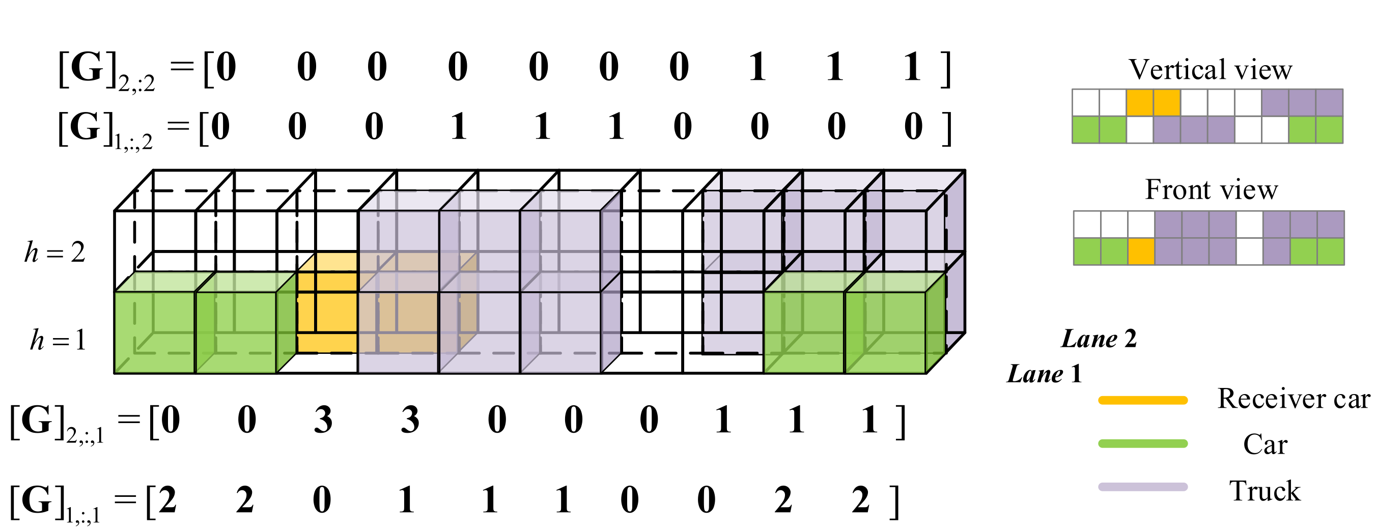
In order to apply the deep learning (DL) method for beam training, we establish a functional relationship between the DL and the beam training. This functional relationship can address the problem of the location describing of the vehicle and the characteristic expressing of its surrounding environment. To address this problem, a 3D grid coding approach is proposed in this paper. On account of the symmetry relationship between the IOV environment and the occupancy grid, the 3D grid coding approach can transform the raw data collected by the sensors into feature patterns, which is applicable for the DL operations.
Encoding the environment by creating an image in a 3D grid is an effective way to produce the feature matrix. We quantify the horizontal area covered by the BS into a regular occupancy grid with a certain granularity , which is quantified by the distance between the centers of horizontally contiguous grids. Moreover, the vertical coverage area of the BS is quantified as an occupancy grid with granularity , which is quantified by the distance between the centers of vertically contiguous grids. Assume that the size of the simulated area covered by the BS is and the height of it is . Then the occupied grid of the simulation area can be represented by a matrix , where the denotes the rounding operation.
Considering the V2I communication scenario established in Section 2, there are three types of vehicles in the grid: adjacent trucks, adjacent cars, and cars where the receivers are located. We define the number of lanes as l and the height of the simulated area as h, where , and . In order to facilitate the operation, we restrict the height of the car into a grid with and the truck into the grid with or . An illustration of 3D encoding of the occupancy grid is shown in Figure 2. If there are no vehicles in the g-th grid of the l-th lane, we set ; If the grid is occupied by a truck, we set , where ; If the grid is occupied by a car (excluding the car with the receiver), we have and . If a car equipped with a receiver is in a grid, we have and , because the receiver is installed in a small car with a low height. The environmental coding model can be expressed as:
where l is the number of lanes, , , and , are the type of vehicle at the current location and they can be quantified as 0, 1, 2, 3. Note that categorical variables 1, 2, 3, and 0 of the vehicles defined in this paper can be further coded as 1000, 0100, 0010, and 0001 to facilitate computer calculations.
Since the symmetry-based 3D grid encoding has some characteristics similar to an image composed of pixels, its grid type features offer great flexibility. Environmental coding with 3D grids allows any type of urban environment to be encoded into an image. Since DL algorithms can effectively use image type features to train and predict, the 3D grid coding is more suitable for the DL algorithm to work than conventional Cartesian coordinate coding and 2D grid coding. However, due to quantization, there is a loss in the encoding of vehicle locations and types by using the 3D occupancy grid. High quantization resolution can enlarge feature dimensions and increase calculation costs, while using lower quantization resolution cannot provide accurate vehicle location and type features.
3.2. Label Iterative Optimization
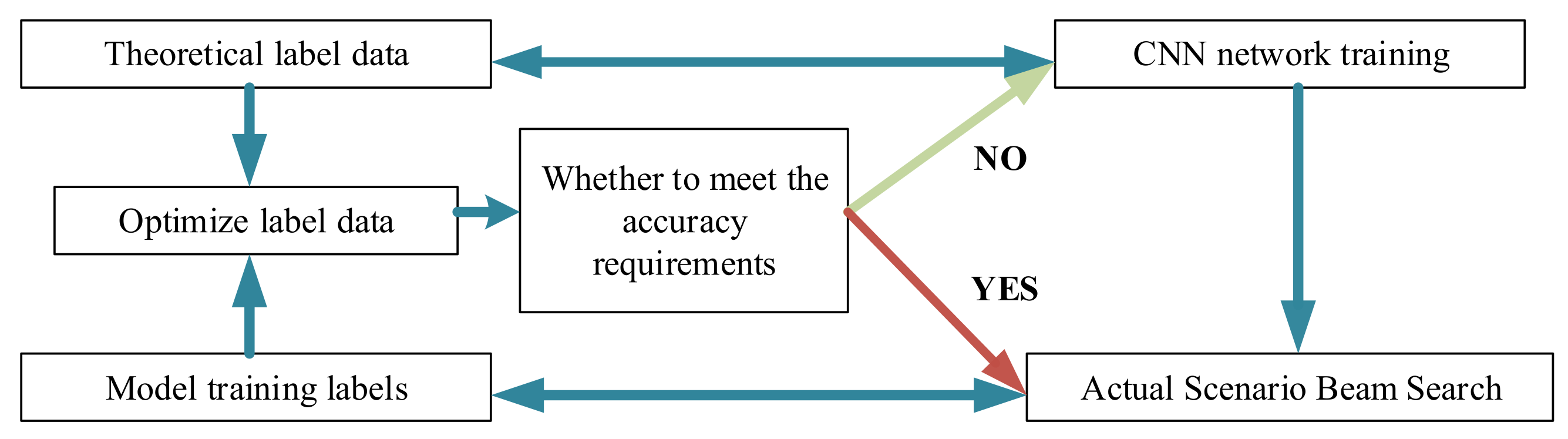
In this paper, an iterative label optimization method is developed. The CNN-based beam searching method is a kind of supervised DL approach. It requires prior information to produce labeled data for neural network training, which can help it to recognize and predict the unknown IOV communication scenes. Therefore, the correctness of labeled data is the key point which can affect the accuracy of the beam search methods [31]. The representativeness and the pervasiveness are considered as the judgment criteria of the labeled data correctness. According to these two criteria in the labeling process, we discuss whether the vehicle situation in an actual scenario can be reflected by the optimal BPI obtained through the training operation, and whether the generalized ability of the network model can be well revealed after the DL operation.
The theoretical label data obtained using the ray-tracing simulator is a good representation of the current scene. However, due to the complexity and diversity of vehicle scenarios in the real world, obtaining matching results in real time becomes a very time-consuming work and the creating of ’big data tags’ turns into a very difficult problem. To address this issue, we propose a tag iteration optimization approach in this paper.
The procedure of label iterative optimization is shown in Figure 3. Assuming that the training dataset is , , and the corresponding predicted values can be expressed as:
where i is the BPI of the a-th training data. After iteration, we can obtain the labeled dataset and the feature matrix dataset expressed as follows:
where t is the number of iterations, i is the BPI and G is the environmental feature matrix. Detailed label iterative optimization steps are provided in Algorithm 1.
| Algorithm 1 Label Iterative Optimization in Algorithm |
|
The basic principles of Algorithm 1 can be described as follows:
- (1)
- Firstly, the labeled dataset obtained by the ray tracing method is applied to train the first neural network model using the CNN algorithm, and then the matching results of 1000 simulated scenes are achieved.
- (2)
- The training results of the first step are segmented and divided according to the size of the label data, and then re-added to the original label dataset to increase the quantity and representativeness.
- (3)
- The new label dataset is used to retrain the neural network model and new label predictions are obtained.
- (4)
- Steps (2) and (3) are repeated until the beam matching results are satisfactory. The final optimized label dataset and its corresponding neural network model are considered as the optimal criterion for subsequent beam matching in the real scene.
- (5)
- The optimized neural network model is employed to complete the beam searching of the final real scene.
3.3. CNN-Based Beam Searching Algorithm
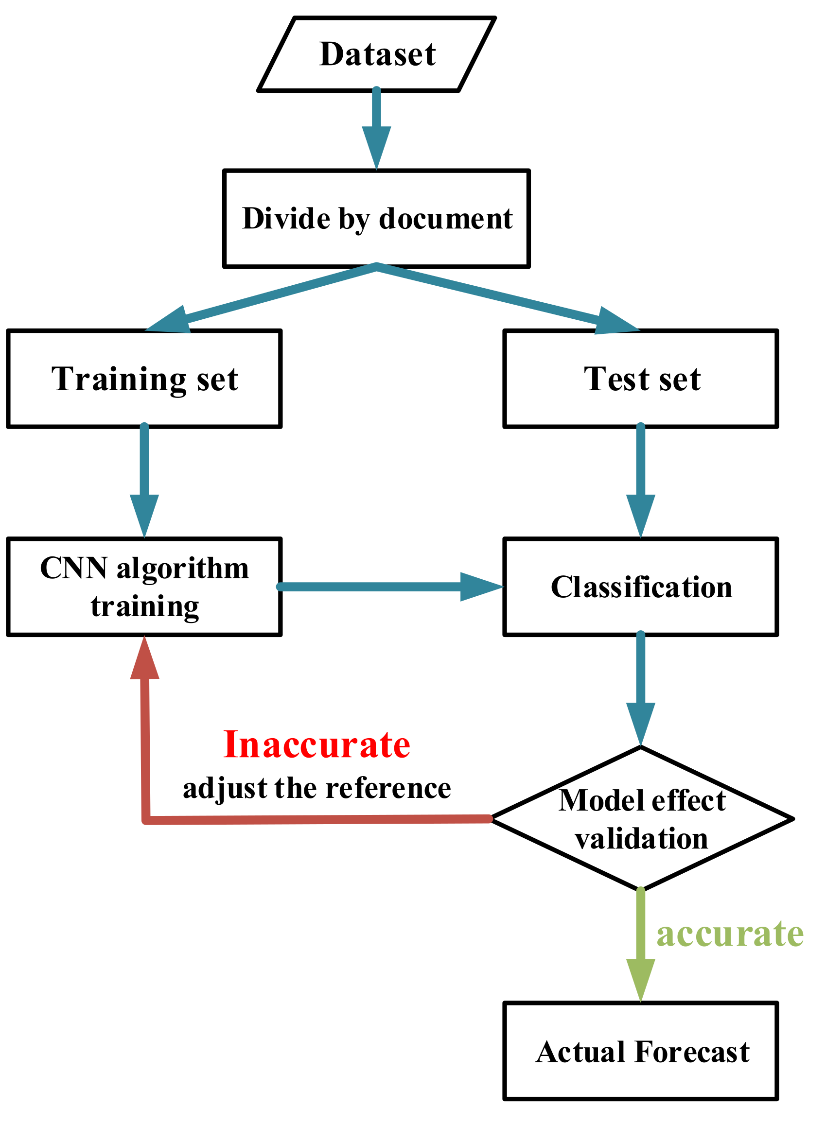
We select environmental parameters, including the locations of vehicles and BS, and the characters of surrounding buildings as features, and obtain the best BPI as a label simultaneously. By using these selected parameters and the CNN method to train the model, we classify and predict the candidate beams.
We propose a new CNN-based beam selection strategy, which can be divided into two main stages; the training stage and the prediction stage. The specific process, as shown in Figure 4, is in the training stage, where the beam is trained by dividing the dataset into a training set and a test set. The division ratio used in this paper is 80% for the training set and 20% for the test set. We train the classifier with the training set and verify the performance of the DL model using the test set [29]. Finally, by optimizing the parameters, we can obtain a well-trained DL model. In the actual prediction stage, the trained DL model is used to classify and predict the beams in a real scene to achieve the best beam pair. After finishing the work of the two stages, the obtained training model is used for actual beam selection. Note that the difficulty of the proposed algorithm implementation is mainly dependent on BPI optimization for the corresponding environmental features.
4. Simulation Results and Analysis
In order to demonstrate the effectiveness of the CNN-assisted V2I beam searching strategy, the alignment probability [32] is used as the evaluation criterion, which can be expressed as:
where denotes the predicted BPI of the i-th ample data in the test set obtained by the training CNN model, is the optimal BPI defined above, m is the total number of samples in the test set obtained after the database division, and is an arithmetic symbol. If , we have and .
We assume a two-lane straight urban scenario, and the length of the investigated street is set to 200 m. Buildings are randomly distributed, and only small cars and large trucks are considered. Note that the effects of pedestrians and trees are ignored. The BS is placed at the roadside, and it is 100 m from the middle of the road. When ray tracing is performed, the effects of reflection, transmission and diffraction should be considered [33]. In every scene, the strongest 25 paths are selected for beam comparison. The detailed parameters can be found in Table 1.
4.1. Alignment Probability Performance Comparison
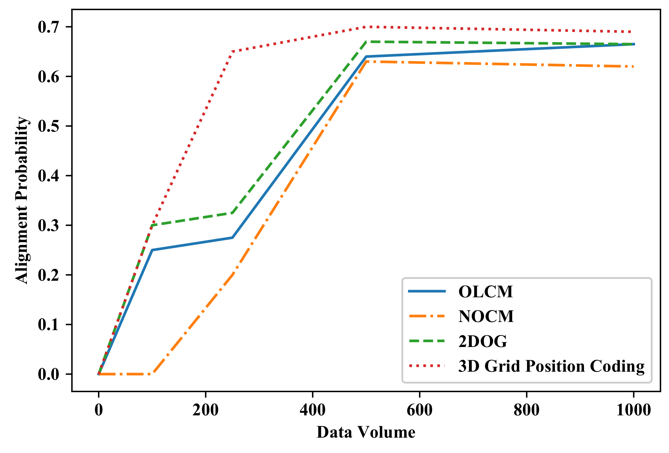
In this paper, 80% and 20% of 1000 samples are used as two disjoint datasets for training and testing, respectively. In order to demonstrate the 3D grid coding method proposed in this paper, the performance of three typical coding methods, namely the ordered location coding method (OLCM) [34], natural order coding method (NOCM) [35] and two-dimensional occupancy grid (2DOG) [29] are also provided.
The alignment probabilities of these methods with the same CNN model are shown in Figure 5. We can see that the 3D grid coding method achieves the best performance in terms of the alignment probability by comparing with the other typical methods. This is because our proposed method orders the location features based on the positions, heights, and lanes of all vehicles in the target scene, taking into account the influence of neighboring vehicles. It is worth mentioning that when the amount of sampling data is small, the performance of the 3D grid coding method is still excellent and the growth rate is relatively smooth. This indicates that the CNN model trained by 3D grid coding can deal with the dataset disequilibrium well even with a relatively small data size.
4.2. Noise Characteristics
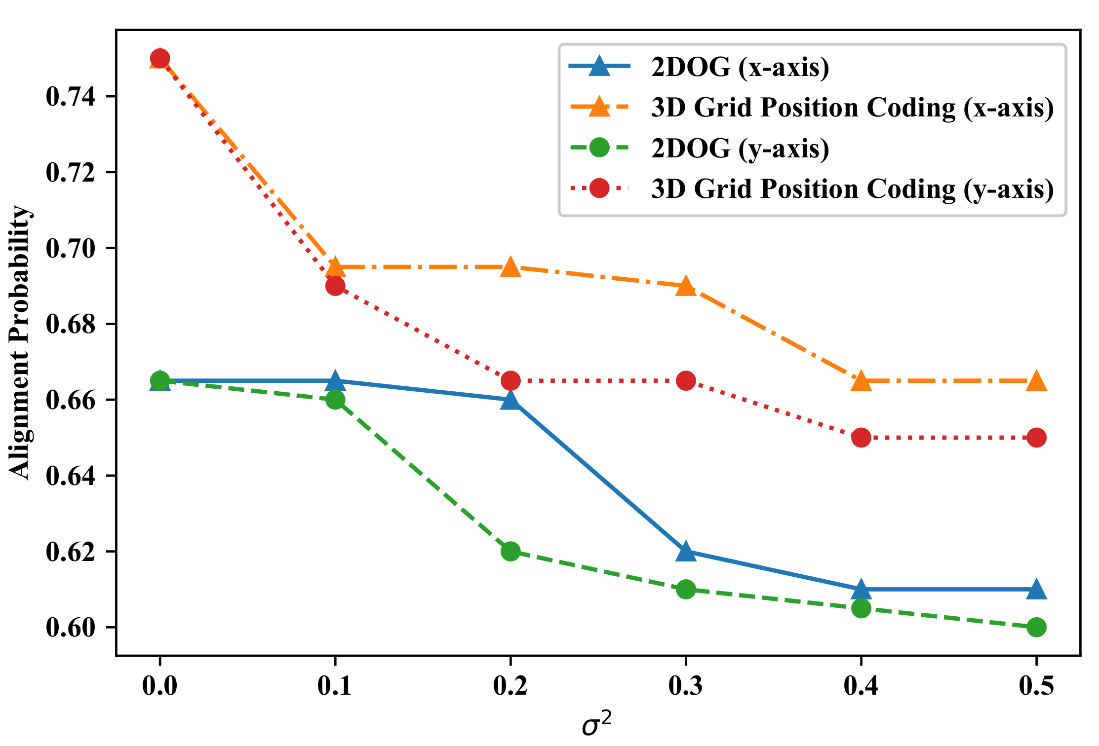
The location information of vehicles is generally acquired by sensors such as radar, GPS, etc. However, all of the sensors have certain measurement errors. In this paper, the Gaussian distribution is used to model the positioning error along two coordinates of the x-axis and y-axis. In the x-axis, the positioning error is directly added to the vehicle location, and in the y-axis, the added positioning error is quantified to the lane index. Lane changes may lead to incorrect environmental feature vectors and result in larger beam alignment errors. The localization error should be added to both the testing set and the training set. In this case, we add positioning errors to the 2D and 3D coding methods.
The comparison of alignment probabilities at different positioning accuracy levels with the CNN model is shown in Figure 6. We can see that inaccurate coordinate positions have a large impact on the prediction accuracy. The error in the y-axis has a greater impact on alignment probability, since the error in the y-axis represents the deviation of the lane. The simulation results also prove that the CNN-trained model with 3D grid coding has better performance than typical 2DOG. Therefore, our proposed method has good immunity to positioning errors provided by different sensors.
4.3. Effectiveness Evaluation of Environmental Situation Awareness
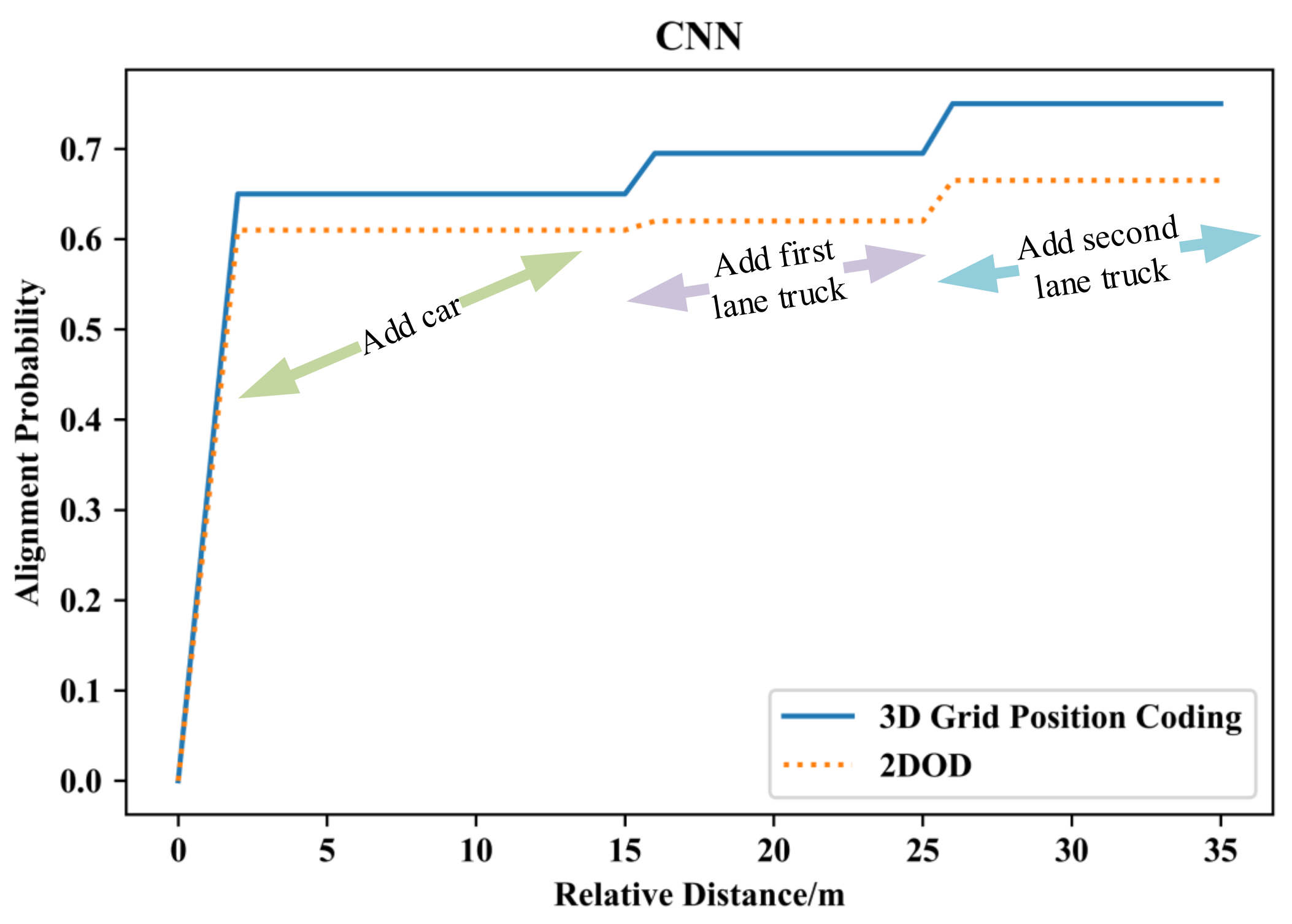
In this section, we evaluate the performance of the trained model by incorporating different degrees of situational awareness. We quantify the degrees of situational awareness by completing the environmental information, as shown in Figure 7, where three degrees of situational awareness are presented. We first start by using all cars, and then add additional features, i.e., the first-lane trucks and the second-lane trucks locations, sequentially. With features classification, the simulation results are shown in Figure 7. Figure 7 shows that the alignment probability is about 65% after adding all cars as a feature, and the alignment probability increases to 75% with adding a truck in the second lane. The results indicate that the trucks in the second lane are closer to the receiver and the huge size of the truck has a greater impact on the receiver than small cars, resulting in a significant increase in the probability of alignment.
4.4. Iterative Optimization Effect Validation
Figure 8 shows the performance of the proposed iterative optimization method for labeled data in this paper. As mentioned above, CNN-based beam searching is a kind of supervised machine learning method, and the correctness of the label data becomes the core element affecting the accuracy of the search results. It can be seen that the performance of alignment probability obtained by using our iteratively optimized label-data is significantly better than that by using only theoretical label-data. The simulation result also shows that after several iterations of optimization, the curve of alignment probability tends to be stable and can achieve a satisfactory result of nearly 95%.
Figure 9 shows the simulation results of the iterative optimization of 10 tags with different positioning accuracies. The results show that after labels iterative optimization, the impact of the positioning errors becomes small. It is worth mentioning that the alignment probability only changes by about 5% when the positioning error reaches 0.5. Figure 9 also shows that comparing with the y-axis, the alignment probability of the x-axis decreases slightly. This is because the positioning error of the x-axis can only change the vehicle position. However, the positioning error of the y-axis results in a positioning error of lane, which has a relatively large impact on the performance.
5. Conclusions
In this paper, a beam searching strategy using the CNN model has been proposed for IOV mmWave communications. We have obtained the environmental features through vehicle situational awareness to establish the database, and encoded the environmental features in a 3D grid type by using label iterative optimization. We have trained the CNN model by the optimized database and used the trained model to compare the target vehicle with the existing features library to find the optimal beam pair. The performance of the proposed 3D grid coding has been evaluated in the urban scenario by comparing with OLCM, NOCM and 2DOG. The simulation results have demonstrated that the proposed strategy can effectively reduce the beam search overhead while guaranteeing the matching accuracy of the beam alignment requirements. Simulation results have shown that our proposed method outperforms OLCM, 2DOG and NOCM by about 0.4%, 0.5% and 1% in terms of alignment probability, respectively. Meanwhile, the proposed label iterative optimization methods can further improve the beam search accuracy by about 3% compared to unoptimized method. In the future, some other communication scenarios will be performed to verify the effectiveness of the strategy presented in the paper.
Author Contributions
Conceptualization, L.Z. and W.Z.; investigation, L.Z., J.Z., Z.Y. and J.W.; software, L.Z. and W.Z.; writing-original draft preparation, L.Z., J.Z. and Z.Y.; writing-review and editing, L.Z., W.Z., J.Z., Z.Y. and J.W.; funding acquisition, W.Z. and Z.L. All authors have read and agreed to the published version of the manuscript.
Funding
This work was supported by the National Key Scientific Instrument and Equipment Development Project under Grant No. 61827801.
Institutional Review Board Statement
Not applicable.
Informed Consent Statement
Not applicable.
Data Availability Statement
The code used for the numerical computations are available upon request.
Acknowledgments
The authors are thankful to anonymous reviewers for their instructive reviewing of the manuscript.
Conflicts of Interest
The authors declare no conflict of interest.
Abbreviations
The following abbreviations are used in this manuscript:
| mmWave | Millimeter wave |
| V2I | Vehicle to infrastructure |
| 3D | three dimensional |
| BPI | Beam pair index |
| CNN | Convolutional Neural Network |
| NOMA | non-orthogonal multiple access |
| IOV | Internet of vehicles |
| RT | Ray tracing |
| 5G | 5th Generation |
| MIMO | multiple-input multiple-output |
| LtR | Learning to Rank |
| CMBA | Combinatorial multi-armed bandit |
| DRL | Deep reinforcement learning |
| BSs | Base stations |
| LOS | Line of sight |
| NLOS | None-LOS |
| UPA | Uniform planar arrays |
| DFT | Discrete Fourier Transform |
| DL | Deep Learning |
| OLCM | Ordered location coding method |
| NOCM | Natural order coding method |
| 2DOG | two dimensional occupancy grid |
References
- Khan, W.U.; Li, X.; Ihsan, M.A.; Menon, V.G.; Ahmed, M. NOMA-Enabled Optimization Framework for Next-Generation Small-Cell IoV Networks Under Imperfect SIC Decoding. IEEE Trans. Intell. Transp. Syst. 2021, 1–10. [Google Scholar] [CrossRef]
- Choi, J.; Va, V.; Gonzalez-Prelcic, N.; Daniels, R.; Bhat, C.R.; Heath, R.W. Millimeter-Wave Vehicular Communication to Support Massive Automotive Sensing. IEEE Commun. Mag. 2016, 54, 160–167. [Google Scholar]
- Huang, S.; Zhang, M.; Gao, Y.; Feng, Z. MIMO Radar Aided mmWave Time-varying Channel Estimation in MU-MIMO V2X Communications. IEEE Trans. Wirel. Commun. 2021, 20, 7581–7594. [Google Scholar]
- Khan, W.U.; Javed, M.A.; Nguyen, T.N.; Khan, S.; Elhalawany, B.M. Energy-Efficient Resource Allocation for 6G Backscatter-Enabled NOMA IoV Networks. IEEE Trans. Intell. Transp. Syst. 2021, 1–11. [Google Scholar] [CrossRef]
- Khan, W.U.; Jameel, F.; Sidhu, G.A.; Ahmed, M.; Li, X.; Jäntti, R. Multiobjective Optimization of Uplink NOMA-Enabled Vehicle-to-Infrastructure Communication. IEEE Access 2020, 8, 84467–84478. [Google Scholar]
- Xu, X.; Liu, M.; Xiong, J. Key technology and application of millimeter wave communications for 5G: A survey. Cluster Comput. 2019, 22, 12997–13009. [Google Scholar]
- Niu, Y.; Li, Y.; Jin, D. A survey of millimeter wave communications (mmWave) for 5G: Opportunities and challenges. Wirel. Netw. 2015, 21, 2657–2676. [Google Scholar]
- Tan, Y.; Wang, C.; Jesper, Ø.; Gert, F.; Zhu, Q. A Novel B5G Frequency Nonstationary Wireless Channel Model. IEEE Trans. Antennas Propag. 2021, 69, 4846–4860. [Google Scholar]
- Qi, N.; Wang, W.; Xiao, M.; Jia, L.; Jin, S.; Zhu, Q. A Learning-Based Spectrum Access Stackelberg Game: Friendly Jammer-Assisted Communication Confrontation. IEEE Trans. Veh. Technol. 2021, 70, 700–713. [Google Scholar]
- ISO/DIS 21216 Std; Intelligent Transport Systems—Communication Access for Land Mobiles (CALM)–Millimeter Wave Air Interface. ISO: Geneva, Switzerland, 2012.
- Liu, L. Algorithm study of beam millimeter wave communication in an optimized searching. Tech. Autom. Appl. 2014, 33, 33–36. [Google Scholar]
- Zou, W.X.; Du, G.L.; Li, B. A novel beam search algorithm for 60 GHz millimeter wave communication. J. Electron. Inf. Technol. 2012, 34, 683–688. [Google Scholar]
- Xiao, Z.; Xia, P.; Xia, X. Channel estimation and hybrid precoding for millimeter-wave MIMO systems: A low-complexity overall solution. IEEE Access 2017, 5, 16100–16110. [Google Scholar]
- Klautau, A.; Batista, P.; Gonzalez-Preclc, N. 5G MIMO data for machine learning: Application to beam-selection using deep learning. In 2018 Information Theory and Applications Workshop (ITA); IEEE: San Diego, CA, USA, 2018; pp. 1–9. [Google Scholar]
- Ali, A.; Gonzalez-Preclc, N.; Heath, R.W. Millimeter wave beam-selection using out-of-band spatial information. IEEE Trans. Wirel. Commun. 2018, 17, 1038–1052. [Google Scholar]
- Asadi, A.; Alex, S.; Sim, G.H. FML: Fast machine learning for 5G mmWave vehicular communications. In Proceedings of the IEEE INFOCOM 2018-IEEE Conference on Computer Communications. Honolulu, HI, USA, 16–19 April 2018; pp. 1961–1969. [Google Scholar]
- Alkhateeb, A.; Alex, S.; Varkey, P. Deep learning coordinated beamforming for highly-mobile millimeter wave systems. IEEE Access 2018, 6, 37328–37348. [Google Scholar]
- Klautau, A.; Gonzalez-Preclc, N.; Heath, R.W. LIDAR Data for Deep Learning-Based mmWave Beam-Selection. IEEE Wirel. Commun. Lett. 2019, 8, 909–912. [Google Scholar]
- Wu, Q.; Ding, G.; Xu, Y. Cognitive internet of things: A new paradigm beyond connection. IEEE Internet Things J. 2014, 1, 129–143. [Google Scholar]
- Ding, G.; Wu, Q.; Zhang, L.; Lin, Y.; Tsiftsis, A.; Yao, D. An amateur drone surveillance system based on the cognitive internet of things. IEEE Commun. Mag. 2018, 56, 29–35. [Google Scholar]
- Dias, M.; Klautau, A.; Gonzalez-Preclc, N.; Heath, R.W. Position and LIDAR-Aided mmWave Beam Selection using Deep Learning. In Proceedings of the 2019 IEEE 20th International Workshop on Signal Processing Advances in Wireless Communications (SPAWC), Cannes, France, 2–5 July 2019; pp. 1–5. [Google Scholar]
- Va, V.; Choi, J.; Shimizu, T. Inverse multipath fingerprinting for millimeter wave V2I beam alignment. IEEE Trans. Veh. Technol. 2018, 67, 4042–4058. [Google Scholar]
- Va, A.; Shimizu, T. Position-aided millimeter wave V2I beam alignment: A learning-to-rank approach. In Proceedings of the 2017 IEEE 28th Annual International Symposium on Personal, Indoor and Mobile Radio Communications (PIMRC), Montreal, QC, Canada, 8–13 October 2017; pp. 1–5. [Google Scholar]
- Rezaie, S.; Manchon, C.N.; Decarvalho, E. Location- and orientation-aided millimeter wave beam selection using deep learning. In Proceedings of the ICC 2020-2020 IEEE International Conference on Communications (ICC), Dublin, Ireland, 7–11 June 2020; pp. 1–6. [Google Scholar]
- Nasim, I.; Ibrahim, A.S.; Kim, S. Learning-based beamforming for multi-user vehicular communications: A combinatorial multi-armed bandit approach. IEEE Access 2020, 8, 219891–219902. [Google Scholar]
- Koda, Y. Millimeter Wave Communications on Overhead Messenger Wire: Deep Reinforcement Learning-Based Predictive Beam Tracking. IEEE Trans. Cogn. Commun. Netw. 2021, 7, 1216–1232. [Google Scholar]
- Huynh, N.; Nguyen, D.N.; Hoang, D.T.; Dutkiewicz, E. Optimal Beam Association in mmWave Vehicular Networks with Parallel Reinforcement Learning. In Proceedings of the GLOBECOM 2020-2020 IEEE Global Communications Conference, Electr Network, Taipei, Taiwan, 7–11 December 2020; pp. 1–6. [Google Scholar]
- Satyanarayana, K.; El-Hajjar, M.; Mourad, A.A.M.; Hanzo, L. Deep Learning Aided Fingerprint-Based Beam Alignment for mmWave Vehicular Communication. IEEE Trans. Veh. Technol. 2019, 68, 10858–10871. [Google Scholar]
- Wang, Y.Y.; Klautau, A.; Ribero, M. MmWave vehicular beam selection with situational awareness using machine learning. IEEE Access 2019, 7, 87479–87493. [Google Scholar]
- Nam, Y.H.; Ng, B.L.; Sayana, K. Full-dimension MIMO (FD-MIMO) for next generation cellular technology. IEEE Commun. Mag. 2013, 51, 172–179. [Google Scholar]
- Zhou, D.; Li, H.; Yan, J. Iterative optimization of label data in CNN algorithm and its application to small fault identification. Prog. Geophys. 2022, 37, 338–347. [Google Scholar]
- Geron, A. Hands-On Machine Learning with Scikit-Learn and TensorFlow: Concepts, Tools, and Techniques to Build Intelligent Systems. O’Reilly Media, Inc: Sebastopol, CA, USA, 2017. [Google Scholar]
- Zhu, Q.; Wang, Y.; Jiang, K.; Chen, X.; Zhong, W.; Ahmed, N. 3D non-stationary geometry-based multi-input multi-output channel model for UAV-ground communication systems. IET Microwaves Antennas Propag. 2019, 13, 1104–1112. [Google Scholar]
- Ngiam, J.; Khosla, A.; Kim, M.; Nam, J.; Lee, H.; Ng, A.Y. Multimodal deep learning. In Proceedings of the 28th International Conference on Machine Learning, Bellevue, DC, USA, 28 June–2 July 2011; pp. 689–696. [Google Scholar]
- Degli-Esposti, V.; Fuschini, F.; Vitucci, E.M.; Barbiroli, M.; Zoli, L.; Tian, X.; Yin, X.; Dupleich, D.A. Ray-tracing-based mm-Wave beamforming assessment. IEEE Access 2014, 2, 1314–1325. [Google Scholar]
Figure 1.
A typical V2I communication scenario.

Figure 2.
An illustration of 3D grid position coding.

Figure 3.
The diagram of the label iterative optimization process.

Figure 4.
The flowchart of the proposed CNN-based searching algorithm.

Figure 5.
The alignment probability vs. the data volume.

Figure 6.
The alignment probability vs. the noise variance.

Figure 7.
The alignment probability vs. the number of vehicle features.

Figure 8.
The alignment probability vs. the iteration number.

Figure 9.
The alignment probability vs. the noise variance.


Table 1.
Simulation parameters.
| Parameter | Value |
|---|---|
| Scenario | Urban |
| Building distribution | Random distribution |
| Carrier frequency | 28 Ghz |
| Antenna (Tx and Rx) | Half-wave dipole |
| Beamwidth | |
| Codebook (Tx and Rx) | DFT |
| Propagation model | X3D |
| Num L of strongest rays | 25 |
| Number of lanes | 2 |
| Length of street | 200 m |
| Vehicles | Car, Truck |
| Length of car and truck | 4 m, 10 m |
| Heights of car and truck | 1.5 m, 2 m |
| Sample size | 1000 |
| Label iteration sample size | 500/1000 |
| Number of antenna arrays () |
Publisher’s Note: MDPI stays neutral with regard to jurisdictional claims in published maps and institutional affiliations. |
© 2022 by the authors. Licensee MDPI, Basel, Switzerland. This article is an open access article distributed under the terms and conditions of the Creative Commons Attribution (CC BY) license (https://creativecommons.org/licenses/by/4.0/).
Share and Cite
MDPI and ACS Style
Zhang, L.; Zhong, W.; Zhang, J.; Lin, Z.; Yang, Z.; Wang, J. mmWave Beam Tracking for V2I Communication Systems Based on Spectrum Environment Awareness. Symmetry 2022, 14, 677. https://doi.org/10.3390/sym14040677
AMA Style
Zhang L, Zhong W, Zhang J, Lin Z, Yang Z, Wang J. mmWave Beam Tracking for V2I Communication Systems Based on Spectrum Environment Awareness. Symmetry. 2022; 14(4):677. https://doi.org/10.3390/sym14040677
Chicago/Turabian StyleZhang, Lulu, Weizhi Zhong, Junjie Zhang, Zhipeng Lin, Zhuoming Yang, and Junzhi Wang. 2022. "mmWave Beam Tracking for V2I Communication Systems Based on Spectrum Environment Awareness" Symmetry 14, no. 4: 677. https://doi.org/10.3390/sym14040677
Note that from the first issue of 2016, this journal uses article numbers instead of page numbers. See further details here.