
Scientometric Analysis for Mechanical Performance of Broken-Line Long-Span Steel Structure in Construction Considering Geometric Nonlinearity


1
Key Laboratory of New Technology for Construction of Cities in Mountain Area, Ministry of Education, Chongqing 400054, China
2
School of Civil Engineering, Chongqing University, Chongqing 400044, China
*
Author to whom correspondence should be addressed.
Symmetry 2021, 13(7), 1229; https://doi.org/10.3390/sym13071229
Submission received: 26 April 2021
/
Revised: 4 July 2021
/
Accepted: 4 July 2021
/
Published: 8 July 2021
Abstract
:A structure does not reach a stable state during the construction process, and hence its structural reliability is low. In order to ensure the safety of the construction process and final structural quality, it is necessary to analyze the safety and structural mechanical properties of large-span space steel structures during the construction process. Based on the engineering background of the polyline symmetrical large-span steel structure construction process, this research established a finite element model of the large-span steel structure on an ANSYS platform. The correctness of the model was verified by comparing the measured frequency of the large-span steel structure with the frequency calculated in the finite element model. Based on the life-death element method, the internal force and deformation response characteristics of the large-span steel structure in the construction process were analyzed, and the different effects of the on-time completion and step-by-step construction on the performance of the broken-line large-span steel structure were compared and analyzed. The study found that the long-span steel truss structure is more sensitive to the construction process, and the final forming state is greatly affected by the construction process. The construction sequence is different, and the structure process and size and distribution of the final stress and deformation are also different. The analysis result of the construction process is closer to that of the actual project. Therefore, appropriate construction paths should be used in the construction process to reduce the impact of path effects on structural performance. It is recommended to pay more attention to the displacement and stress response of the truss when it encounters similar a symmetrical long-span steel structure truss in-place of the forming construction.
1. Introduction
At present, with the improvement in economic levels and the continuous development of science and technology, mankind has put forward more complex appearance requirements and functional requirements for buildings. Due to its good mechanical properties, a large-span spatial steel structure [1] can achieve complex structural forms and functional requirements, and have a beautiful and simple appearance. It can be used in theaters [2], gymnasiums [3,4], museums [5], exhibition halls [6], and art centers [7]. It has many applications in airport terminals [8] and industrial plants [9]. Therefore, the demand for construction of spatial steel structures with huge spans and complex shapes is increasing in real life.
The analysis of the mechanical properties of long-span steel structures has always been a hot topic in the field of steel structure research. At present, most scholars are committed to the study of the normal use stage of large-span steel structures [10], mainly focusing on the dynamic characteristics of steel structures [11], seismic performance [12,13,14,15], wind resistance [16], fire resistance [17], temperature stress-effects [18], earthquake damage reduction [19], snow resistance [20], damage mode for earthquakes [21], comfort [22], and economy [23], among others.
At present, there is little research on the mechanical properties of large-span steel structures during the construction process, and studies on the force and path analysis of large-span steel structures during construction is relatively scarce. However, the most dangerous stage of a structure is not in the normal use stage, but in the aging and construction stages [24]. In the process of engineering construction, structural resistance and loads are dynamically changed, and the structure is in an unsteady state, failing to form a complete structural system. An incomplete structure may topple over due to loss of balance, collapse due to loss of stability, or be damaged due to insufficient strength [25], and failure probability is significantly higher than during normal use.
Therefore, studying the mechanical properties of large-span steel structures in the construction process is of great significance in the construction process. This paper analyzes the construction process of a broken-line large-span spatial steel truss. Based on the time-varying structural mechanics theory and nonlinear analysis solution method, the difference between the step-by-step construction process and the one-time forming process is analyzed by using the life-death element method [26]. The path effect in the construction process is also solved. By establishing an overall structure model combining roof truss structure and temporary support, the method of activating the truss section gradually after killing all the elements is used to simulate the in-place forming of the truss construction, and the spatial maximum response and time history characteristics of the structure are analyzed.
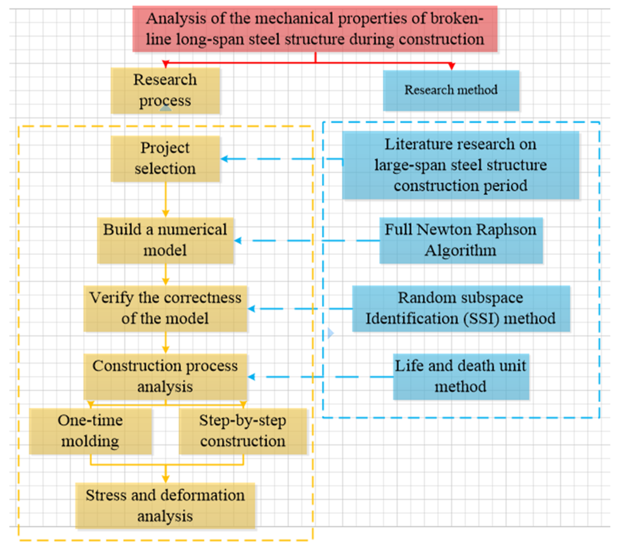
Analysis of the mechanical performance of a broken-line large-span steel structure during the construction period mainly includes the research process and research methods. Both stages consist of several steps, as shown in Figure 1. The flowchart followed in this study is given in Figure 1 for a comparative analysis.
2. Mechanical Analysis of the Construction Process Based on a Time-Varying Structure
2.1. Time-Varying Structure and Principles of Construction Mechanics
No matter how large the volume of the building structure and how complicated the structure is, the essence of structural analysis is always mechanical analysis. The theoretical basis of the whole process analysis of structure construction is construction mechanics, which belongs to a branch of time-varying mechanics, and is a four-dimensional mechanical problem that couples time and space. The structure in which the structure itself changes with time is called a time-varying structure, and the mechanics of studying a time-varying structure is called time-varying mechanics. Among them, the branch that studies the structural force during civil engineering construction is construction mechanics [27]. During the construction of the structure, material strength changes with age, the temporary structure of the construction is constantly added or subtracted, the structural system is constantly changing, and the load on the structure is also constantly changing. The analysis object itself will constantly change, which is the biggest difference between construction mechanics and traditional structural analysis.
2.2. Construction Mechanics Analysis Method
In time-varying structural analysis, the most commonly used analysis methods are step-by-step modeling and life-and-death element methods [28,29]. The step-by-step modeling method is a method of modeling and loading calculation step-by-step in accordance with the construction sequence. After single-stage analysis of the previous life and death is completed, the new components are modeled on the deformed model to enter the next stage of simulation. However, due to discontinuity of the model establishment, the stiffness matrix of each stage will change in size and order due to the changes in the number of structural nodes and the number of elements, so it is difficult to achieve in actual analysis. Therefore, the life-death element method is currently used more frequently. The life-death element method is a finite element method that realizes the addition or deletion of selected parts of the model through the activation or killing of the elements and the finite element method that simulates the addition or withdrawal of materials. In actual engineering, it can be applied to structural time-varying problems, such as geotechnical engineering excavation, structural installation, and dismantling. The life-and-death element method can calculate the entire process in one modeling, and realize the continuity of the model. The next stage of structural modeling analysis is based on the internal force and deformation of the previous stage of structure, reflecting on the mutual influence between the construction stages. Calculation of structural time-varying is mainly reflected in the change of the stiffness matrix. The life-death element method is realized by multiplying the stiffness matrix by the element life and death coefficient. The analysis principle is:
The construction process is divided into N construction phases, and the corresponding structure is also divided into N parts, which are called structure 1st, structure 2nd… structure nth, assuming that the structure in each stage is constant, analyze each stage separately. represents the stiffness matrix of the structure i in the jth construction section, represents the load array of structure i in the jth construction section, and represents the displacement of the overall structure of the jth construction section.
First, establish the full model of structural analysis. At this time, the overall control equation of the structure is Equation (1):
Here, kill all units and change the structure to its initial state. By multiplying the stiffness matrix by the life and death element coefficient , the total stiffness of the structure is close to 0, and all loads are set to zero at the same time. The governing equation at this time is Equation (2):
Activate the corresponding units according to the construction sequence, simulate the construction forming process of the structure, and apply the corresponding boundary conditions and loads to obtain the force situation at this stage. The governing equation of the kth stage is Equation (3):
If the component is removed, the element stiffness matrix of the component should be multiplied by the life-death coefficient. At the same time, the internal force of the removed component should be applied to the structure in the opposite direction to modify the structural constraints and load array. After the displacement at each stage is calculated, the corresponding structural strain and stress can be calculated through geometric equations and physical equations.
3. Geometric Nonlinearity of the Structure
The basic equation of linear elasticity has three characteristics: the stress-strain relationship of the constitutive equation is linear, the strain-displacement relationship of the geometric equation is linear, and the equilibrium equation of the state before and after deformation is linear. However, in many practical engineering problems, such as cable elements in pre-stressed structures, the above-mentioned linear relationship cannot be maintained, which leads to structural non-linear problems. Due to the non-linear stress-strain relationship of the material itself (Hooke’s theorem does not hold), the nonlinear response of the structure is called material nonlinearity. Because the structure undergoes large deformation and large rotation, the change in the geometric shape of the structure causes the corresponding nonlinearity of the structure, which is called the geometric nonlinearity of the structure [30]. For large-span steel structures, the design internal force of the material is generally lower than the yield stress, the constitutive equation satisfies the linear relationship, and the geometric nonlinearity issues need to be considered.
3.1. Geometric Equation
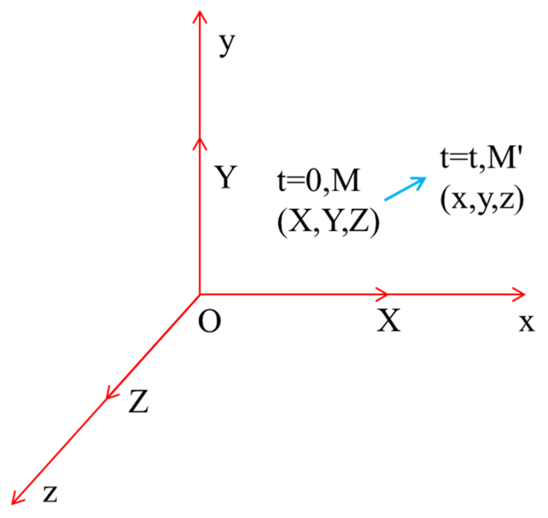
The geometric nonlinearity of the structure is highlighted in the geometric equation; it is a formula describing the relationship between macroscopic deformation (displacement) and microscopic deformation (strain). Suppose there is a point M with coordinates (X, Y, Z) on the deformable body, when the deformed body is subjected to an external force, it will produce displacement to move the point M to the point M’ with coordinates (x, y, z), as shown in Figure 2. In this process, the strain of a point can be described by the initial coordinates, and we call this strain the Green strain [31]. It is shown in Equations (4)–(9).
In addition, we can also use the deformed coordinates as a reference, which is called the Almansi strain [31], and it is shown in Equations (10)–(15).
The Green strain and Almansi strain are both approximate expressions of the first-order partial derivative quadratic formula and linear strain of the displacement to the coordinate, which retains the true strain.
3.2. Physical Equation
In the process of strain, the deformed body will generate stress at the same time. The physical equation acts as a bridge between stress and strain, and the stress and strain in the equation correspond to each other.
Therefore, the Green strain corresponds to Kirchhoff stress S, and Almansi strain corresponds to Cauchy stress σ [31]. At this time, the physical equation of the elastic body can be expressed in Equations (16) and (17):
—six-component engineering Green strain; —six-component engineering Almansi strain —Kirchhoff stress corresponding to six-component engineering strain; —Cauchy stress corresponding to six-component engineering strain; D—constitutive relation matrix, which is a function of the material.
3.3. Balance Equation
In order to ensure the accuracy and stability of the geometric nonlinear problem, the load on the structure is usually loaded on the structure in multiple steps in sequence, that is, the mathematical incremental equation is used to solve the problem. In this way, the physical parameters of the deformable body in equilibrium at discrete time points 0, 1Δt, 2Δt,…, (i − 1)Δt can be obtained. When calculating the physical quantity at time iΔt, the equilibrium configuration at the time (i − 1)Δt is taken as the initial configuration. However, this initial configuration is a function of time, so it is called the updated Lagrange format (Updated Lagrange Formulation, U.L format for short). On the contrary, if the physical initial configuration (the configuration at time 0) is used as the initial configuration, the initial configuration is constant throughout the calculation process, and it is called the Total Lagrange format (T.L format for short). Generally speaking, in order to reduce the amount of calculation when the magnitude of structural displacement under load is large, the U.L format should be adopted at this time.
Assuming that the coordinates of each particle in K_ij represent the stiffness matrix of structure i in the construction section j, F_ij represents the load array of structure i in the construction section j, and δj represents the displacement of the whole structure in the construction section j. The object at time iΔt is ; using to represent the displacement of each particle from time 0 to time iΔt, we can get Equations (18) and (19):
where i = 1, 2, 3, ..., i, ∆ui is the displacement increment of the ith load increment step. Therefore, the balance equation at the moment iΔt is based on the principle of virtual work [31]:
In the above formula, represents the Green strain from (i − 1)∆t to i∆t based on the coordinate system at time (i − 1)∆t, p is physical strength, q is the face force.
4. Engineering Background
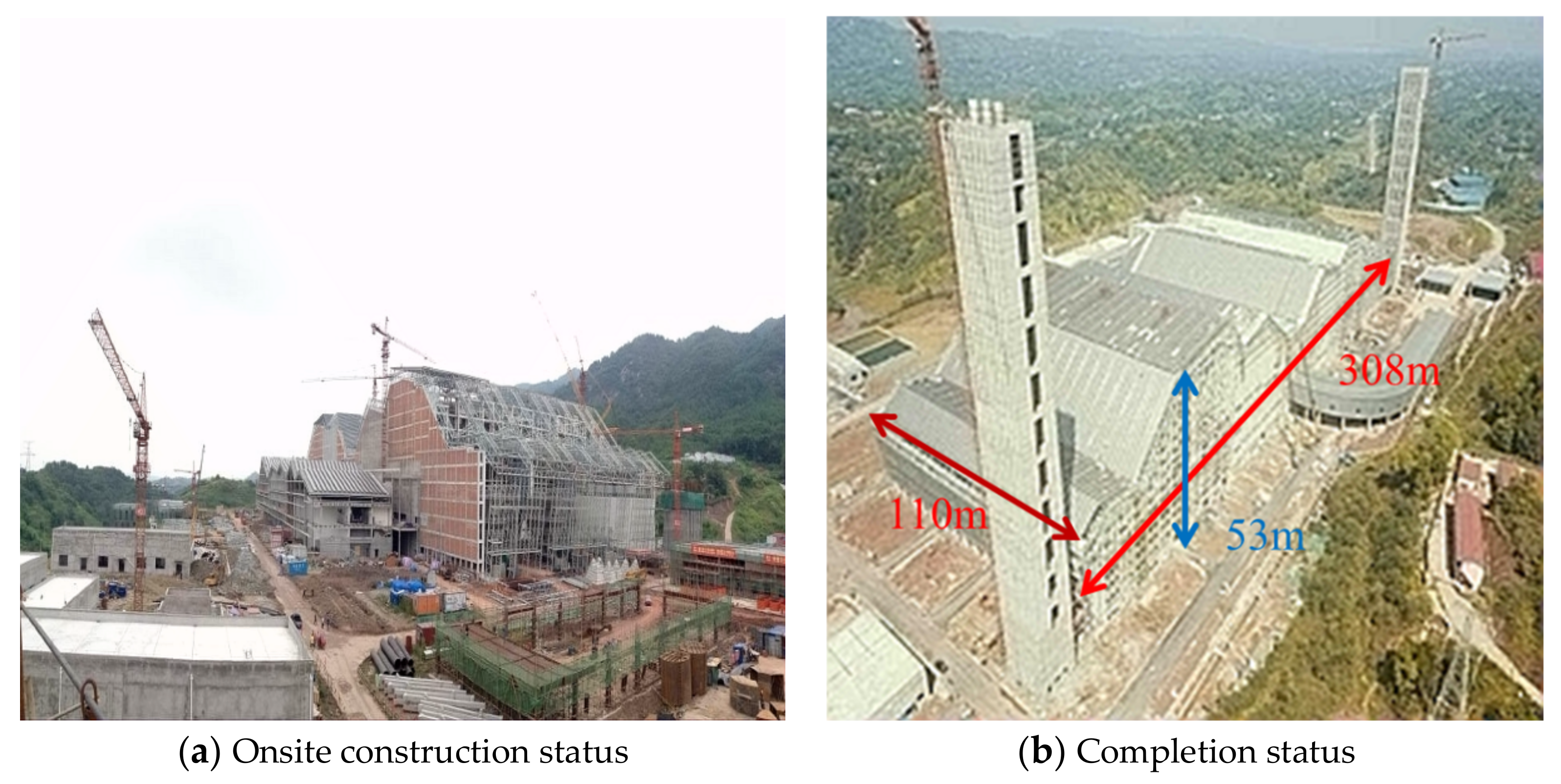
This study is based on the roof project of the third waste incineration power plant (TWIPP) in Chongqing. The roof steel structure is a symmetrical structure with a broken-line multi-span portal type steel pipe truss. Onsite construction and completion are shown in Figure 3. Because the project has a high degree of symmetry and is a typical symmetrical long-span steel structure, it is necessary to study the project. The projected size of the project is 308 m × 110 m, the maximum structure height is about 53 m, and the maximum span is 56 m. The roof is mainly composed of 11 to 7-span circular tube main trusses, 25 triangular circular tube secondary trusses, and a roof support system. The main truss section is inverted triangle and rectangle, and the section size is mainly 3 m × 3.5 m, 3 m × 3 m. Studying the construction process of the project has guiding significance for proposed symmetrical long-span steel structures and those under construction.
5. Numerical Model Establishment and Verification
5.1. Model Establishment
In the actual construction process of a large-span steel truss structure, the overall structure is a symmetrical structural system composed of roof trusses and temporary supports. The force state and displacement of the temporary supports directly affect the spatial position of the roof structure and whether the steel trusses can be accurately connected. Therefore, in the forming process of the long-span steel truss structure, not only the displacement and stress of the steel truss, but also the displacement and stress of the temporary support should be analyzed. In the actual construction process, the standard section of the tower crane was used as the standard section combined tower support. Because the structure uses temporary supports during the actual construction process, in order to be consistent with the actual construction process, temporary supports are also added when establishing the finite element model. Temporary support is only under pressure during actual construction, and Link10 is a rod unit that is axially pulled or compressed, so the Link10 rod unit is used to simulate temporary support.
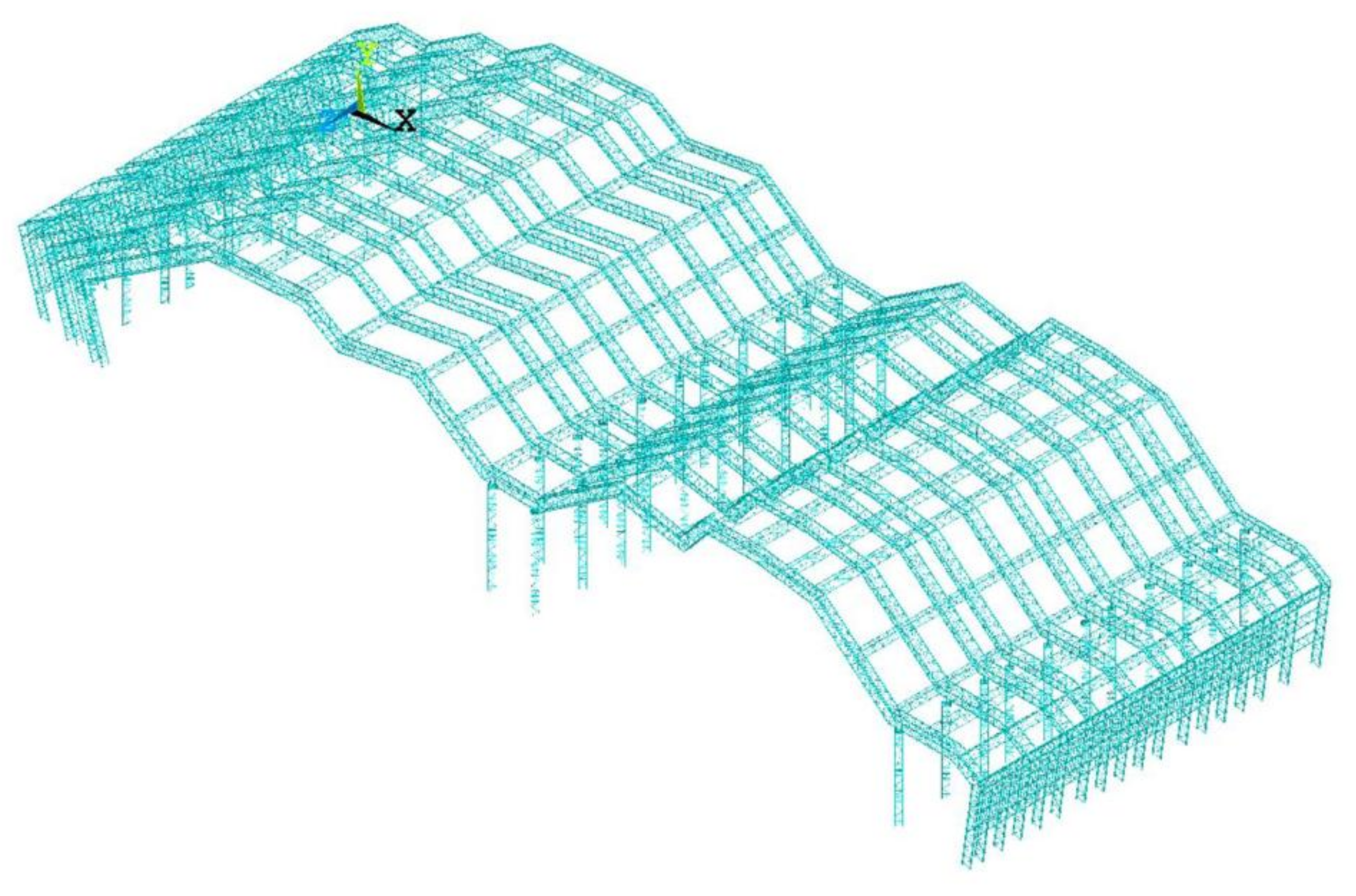
The steel model used in the steel truss structure is Q345. The truss members are simulated by the 3D secondary finite strain beam element beam189, with a Poisson’s ratio of 0.3, damping of 0.05, a density of 10205 kg/m3, and a modulus of elasticity of 206 GPa. This element is based on the Timoshenko beam theory, taking into account the influence of beam shear [32]. In the process of simulation analysis, the material used is assumed to be an ideal elastic material. The upper and lower chords of the space truss bear the combined action of axial force, shear force, and bending moment. Therefore, the main structural members of the steel truss adopt beam element members uniformly, which can consider axial force, shear force, and bending moment, and at the same time release the rod end bending moment for the web members that are only subjected to axial force. Among them, the temporary support and permanent support maintain a rigid connection with the ground, restrict all degrees of freedom, and maintain a hinged connection between the truss members. The large deformation option is used to automatically consider the nonlinear behavior, and the full Newton-Raphson algorithm is used to consider the change of the stiffness matrix between different sub-steps. The solution process will iterate until the results converge, because the stiffness matrix is related to deformation. Figure 4 shows the overall numerical model of the structure established by ANSYS finite element software, considering the updated Lagrange format and the complete Newton-Raphson large deformation. The software version is ANSYS18.0, the manufacturer is American ANSYS, and the country of manufacture is the United States.
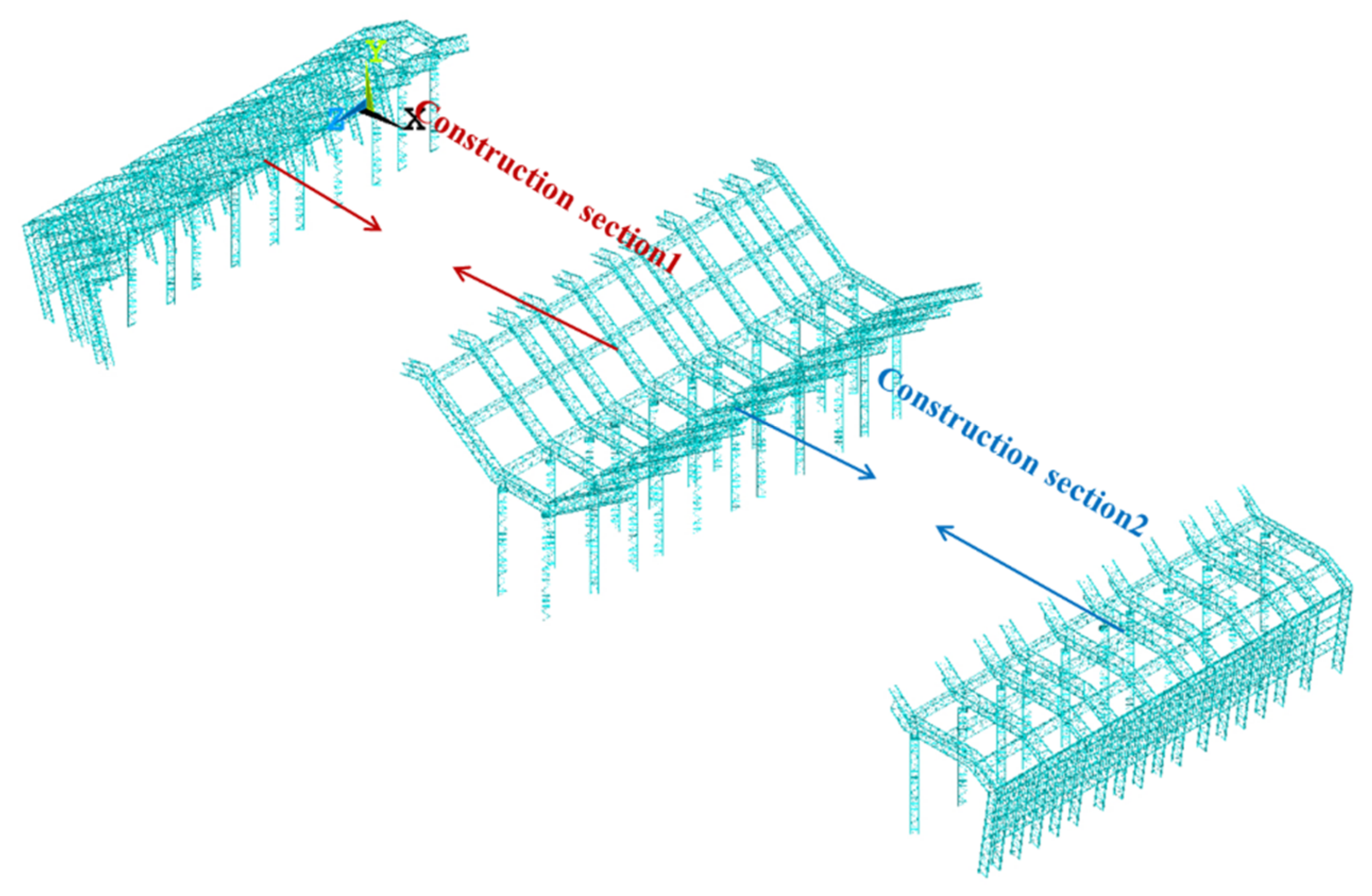
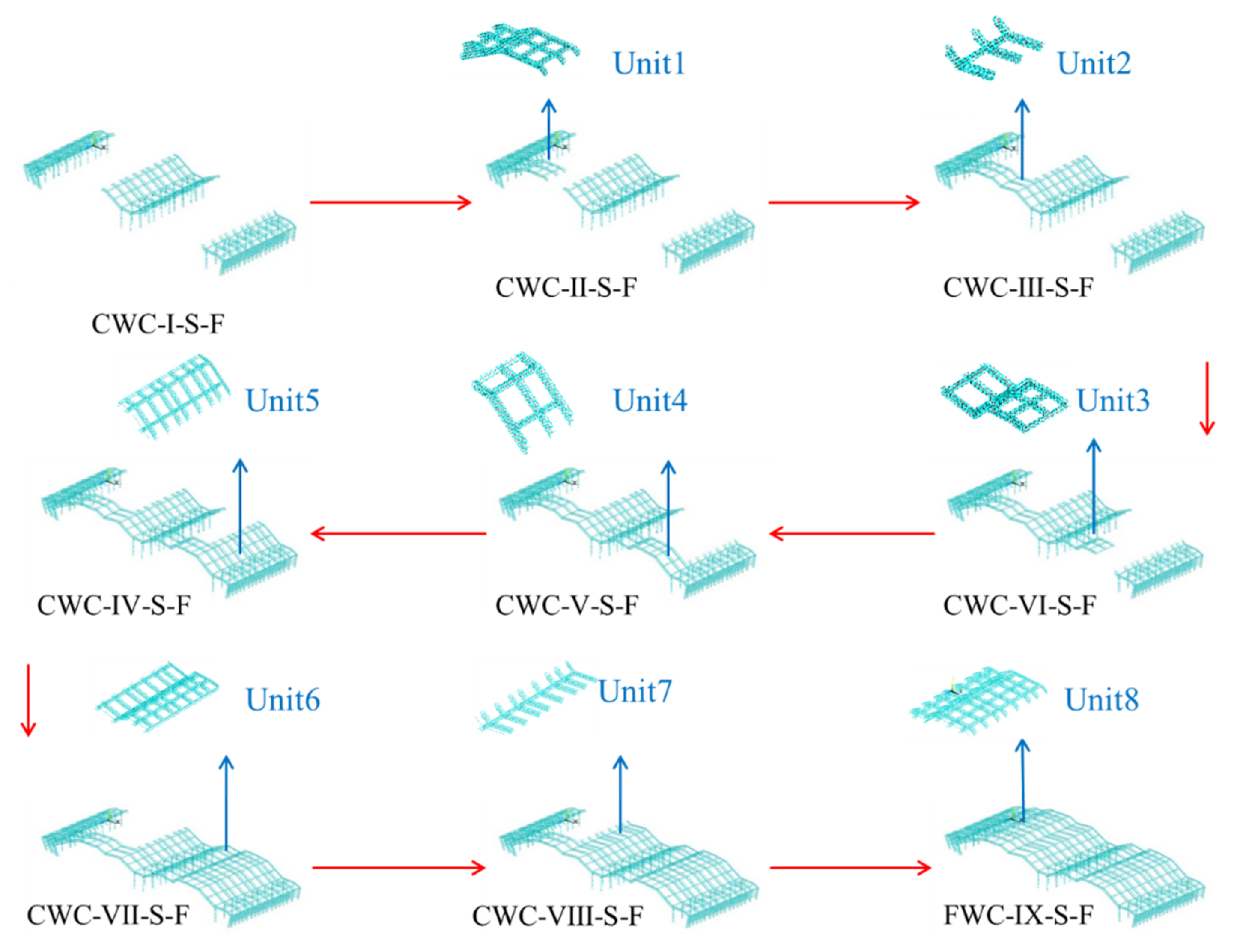
Combining the degree of independence in the truss forming process and the actual construction sequence onsite, the entire construction process is divided into nine working conditions for numerical analysis. The site construction was divided into two construction sections, starting from the side span and mid span, and proceeding to the middle, as shown in Figure 5.
The nine working conditions from the first to the ninth are named CWC-Ⅰ-S-F (where C is Construction, W is Working, C is Condition, Ⅰ is First, S is six permanent supports, F is four permanent supports), CWC-Ⅱ-S-F (where C is Construction, W is Working, C is Condition, Ⅱ is Second, S is six permanent supports, F is four permanent supports), CWC-Ⅲ-S-F (where C is Construction, W is Working, C is Condition, Ⅲ is Third, S is six permanent supports, F is four permanent supports), CWC-Ⅳ-S-F (where C is Construction, W is Working, C is Condition, Ⅳ is Fourth, S is six permanent supports, and F is four permanent supports), CWC-Ⅴ-S-F (where C is Construction, W is Working, C is Condition, Ⅴ is Fifth, S is six permanent supports, F is four permanent supports), CWC-Ⅵ-S-F (where C is Construction, W is Working, C is Condition, Ⅵ is Sixth, S is six permanent supports, F is four permanent supports), CWC-VII-S-F (where C is Construction, W is Working, C is Condition, VII is Seventh, S is six permanent supports, F is four permanent supports), CWC-VIII-S-F (where C is Construction, W is Working, C is Condition, VIII is Eighth, S is six permanent supports, F is four permanent supports), FWC-Ⅸ-S-F (F is Finial, W is Working, C is Condition, Ⅸ is Ninth, S is six permanent supports, F is four permanent supports).
CWC-Ⅰ-S-F is the active state of the mid-span and both side spans. At the same time, all permanent supports and temporary supports are activated in the CWC-Ⅰ-S-F working condition. FWC-Ⅸ-S-F is the fully activated state of the structure. Here, the model is a space structure system composed of the roof and supports, a total of six permanent support supports, four temporary supports, and the roof truss is a twelve-span steel pipe truss structure. Table 1 shows the number of supports in each working condition and the changes in the working condition itself. The sequence of working conditions is shown in Figure 6, and the section types and dimensions of the main components used in this project are shown in Table 2.
5.2. Validation of the Numerical Model
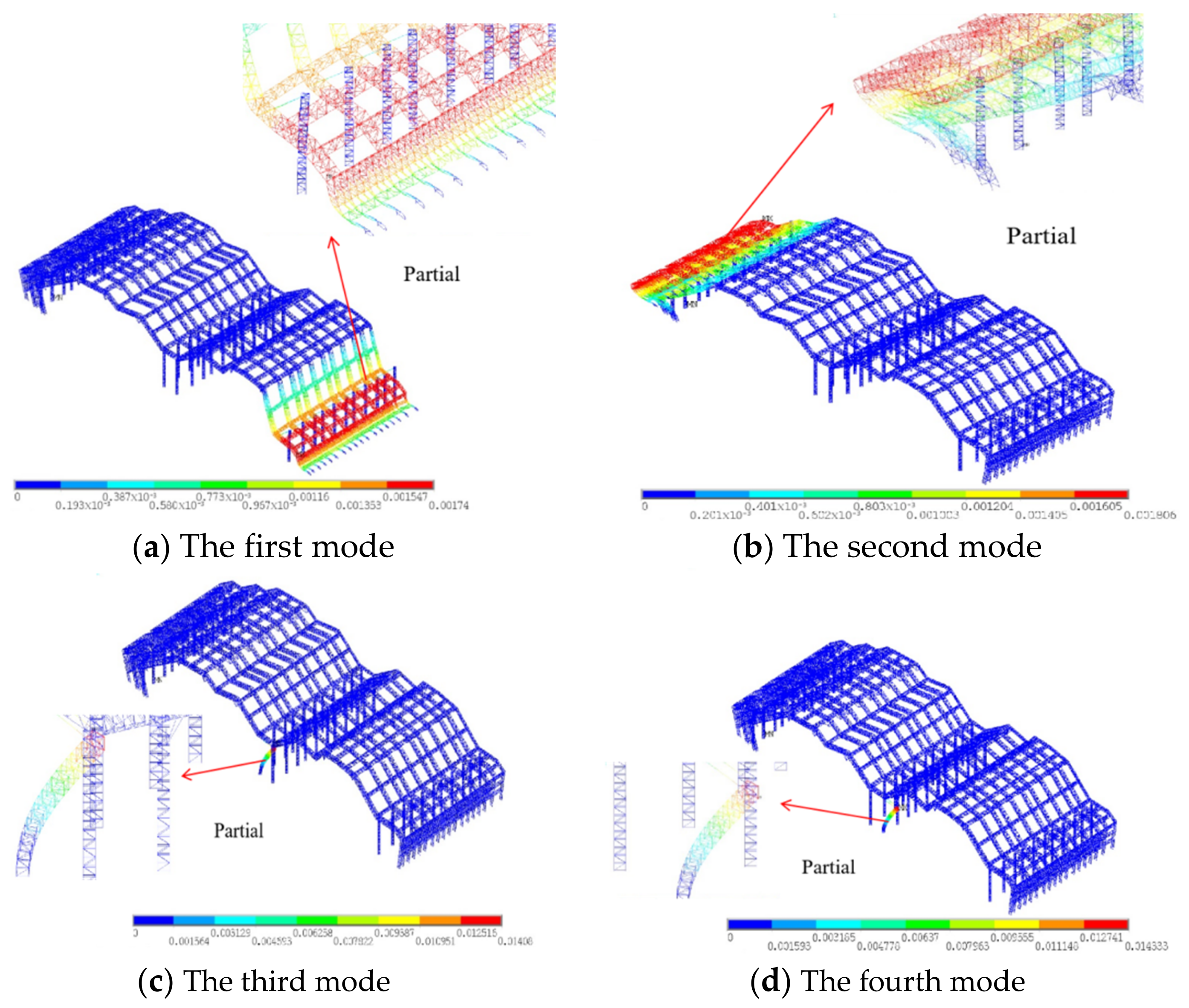
The natural frequency and mode shape of the structure can reflect the main characteristics of the structure. Although the structure has an infinite number of natural frequencies, usually only low-order frequencies are concerned, especially the first order (fundamental frequency). This is because the lower the first-order frequency is, the more sensitive the structure is to external excitation—the contribution of the low-order modes of the structure to the displacement response is greater than the contribution of the high-order modes to the displacement; in the actual structure, the higher modes are often discarded. Although it will cause a certain error, the order of the frequency response function will be greatly reduced, which reduces the workload. This method is used in finite element analysis, which is also called modal truncation [33]. This study uses finite element software to obtain the natural frequency and mode shape of the long-span steel structure and uses the modal truncation method to analyze the first four-order natural frequencies of the long-span steel structure, which are 0.8461 HZ, 1.0703 HZ, 1.4029 HZ, and 1.4286 HZ, respectively. The first four modes are shown in Figure 7.
The following can be seen from the first four-order modal analysis of the large-span spatial steel truss: In the first mode (Figure 7a), the rightmost support of the structure translates in the Z direction, and the part of the truss where the support moves, resulting in X direction translation and Y direction collapse displacement. In the second mode (Figure 7b), the leftmost permanent support of the structure is bent around the Z axis, and the temporary support is displaced in the Z direction, resulting in displacement of the truss in the X and Y directions. In the third mode (Figure 7c), the left permanent support of the middle span produces torsion around the X axis, but since the right support of the middle span has no displacement, there is no significant displacement of the truss at this time. In the fourth mode (Figure 7d), the permanent support on the right side of the middle span of the structure is twisted around the X axis, and the Y axis is displaced at the same time, but the truss has no obvious displacement.
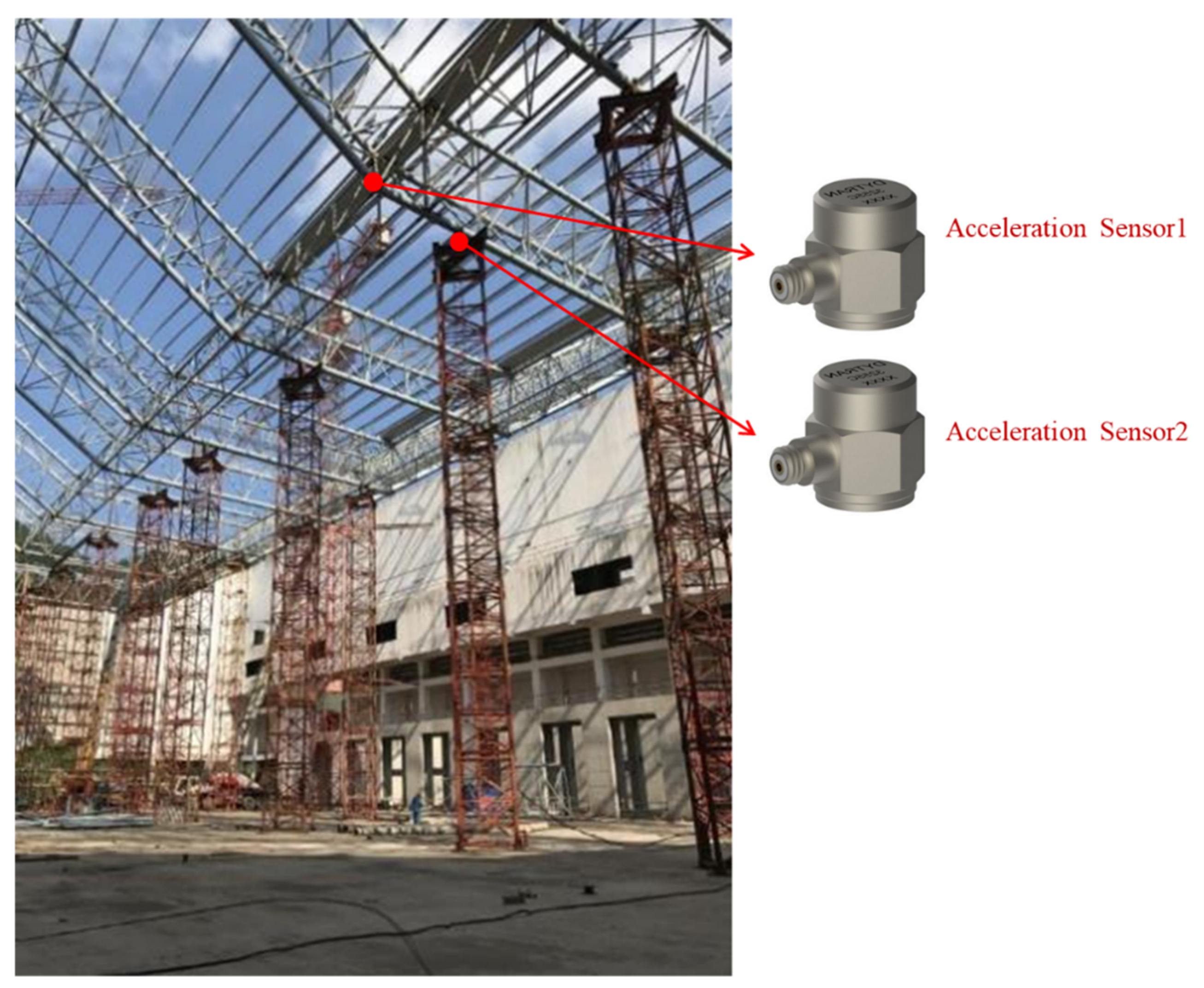
In order to verify the correctness of the numerical model, in this study, the natural frequency of the actual long-span steel structure was obtained by the environmental random vibration excitation method. An integrated circuit piezoelectric (ICP) acceleration sensor and Eastern Coca data acquisition instrument was used to perform data measurement and acquisition. The sampling frequency was 100.0 Hz, and the sampling time was 10.0 min. According to theoretical analysis and onsite construction conditions, the acceleration sensor should be placed in a position with greater structural response [34,35]. The acceleration sensors are respectively arranged at the position where the support and the truss are connected, and at the position where the connection point of the truss beside the support is located. The specific positions are shown in Figure 8.
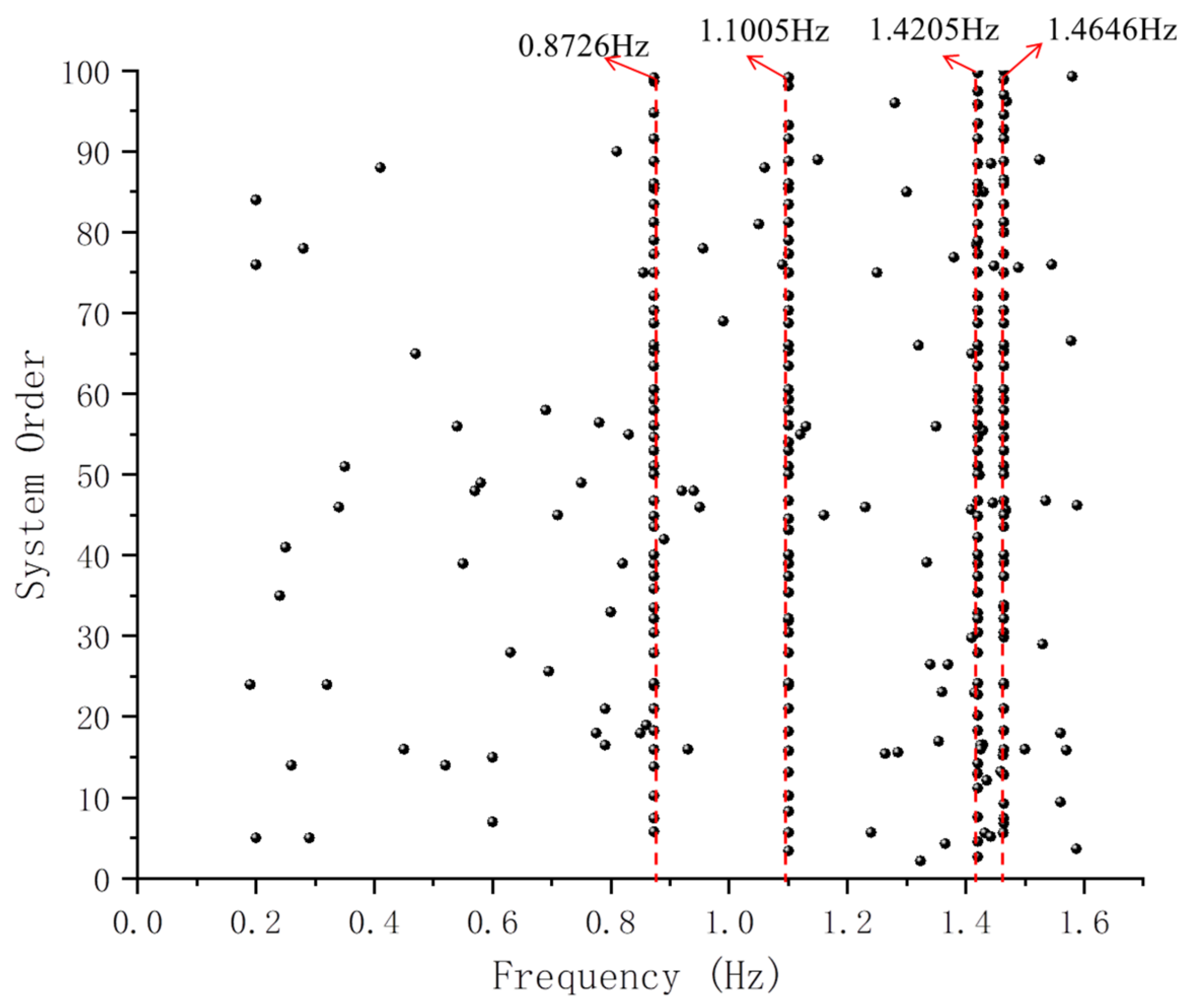
In this study, the stochastic subspace identification (SSI) method was used to identify the natural frequencies of long-span steel structures. The random subspace method is a linear system identification method developed in recent years, which can effectively obtain the modal parameters from the structural response of the environmental excitation. The natural frequencies of the first four-order modes of the long-span steel structure are obtained by the random subspace identification (SSI) method. The natural frequency results of the actual random subspace identification of the long-span steel structure are shown in Figure 9.
The abscissa of the graph is the frequency value, and the ordinate is the order of the system. From the frequency and system order display in Figure 9, it can be seen that the first four natural frequencies of the actual long-span steel structure are 0.8726 HZ, 1.1005 HZ, 1.4205 HZ, and 1.4646 HZ, respectively. The comparison results are shown in Table 3.
From the comparison between the numerical analysis results and the recognition results in Table 3, the minimum error is 1.2578%, the maximum error is 3.13%, the average error is 2.43045%, and the root means the square error is 2.5322%. The natural frequency obtained by the finite element model analysis is basically consistent with the actual structure. Therefore, the finite element model and analysis results of this study are credible.
6. Characteristic Analysis of the Forming Process
In this paper, considering the degree of independence in the forming process of the truss and the construction sequence of the site conditions, in the analysis, the structure forming process was simulated by the life-and-death element technique. The influence of the construction sequence of internal components in the same district was ignored, and the influence of the construction sequence between different districts was focused on.
6.1. Analysis of Stress Changes during Step-By-Step Construction
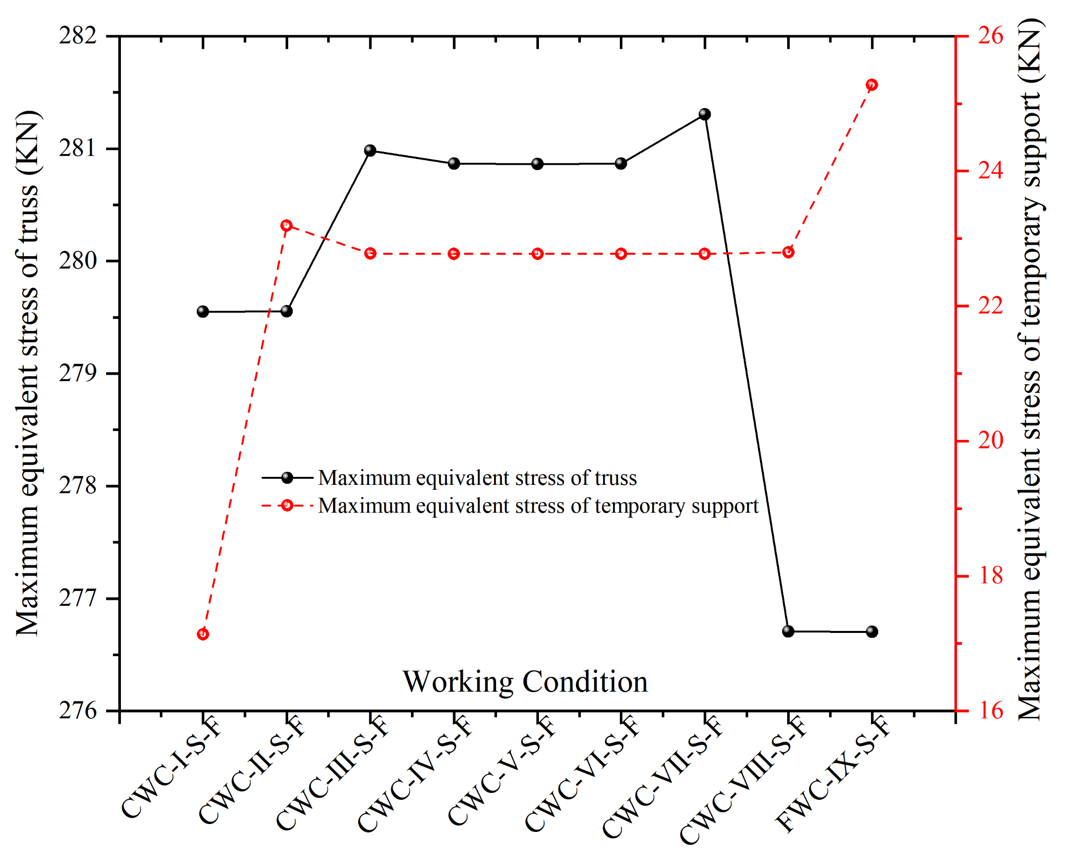
In this paper, the components are continuously activated by the life-and-death element method to realize the process simulation that gradually forms with the construction step structure. The maximum value of the roof truss stress and the maximum value of the temporary support stress of the corresponding working conditions at each time point are obtained. Figure 10 shows the corresponding stress time history curve.
It can be seen from the stress time history curve:
- During the roof forming process, the minimum equivalent stress of the truss is 276.703 MPa, and the maximum equivalent stress of the temporary support is 23.193 MPa. The equivalent stress value of the truss in each working condition is greater than the stress value of the temporary support and less than the yield strength of the material, indicating that the truss is mainly responsible for the stress generated by the self-weight of the rod during the forming process.
- On the whole, the maximum change range of the equivalent stress of the truss is 1.63%, the minimum change range is 0.0014%, the average change range is 0.292%, and the overall change is gentle. Comparing the temporary support, it can be seen that the stress change range of the temporary support from CWC-Ⅰ-S-F to CWC-Ⅱ-S-F is 35.37%, which is much larger than the change range of the truss stress, and there is a sudden change. This shows that the temporary support plays a great role in the safety of the structure during the construction process.
- Whether it is the equivalent stress of the truss or the temporary support, both tend to be stable in the middle of the construction. The changes mainly exist in CWC-Ⅰ-S-F and FWC-Ⅸ-S-F. This is mainly due to the truss structure in the early and late stages. The changes are great.
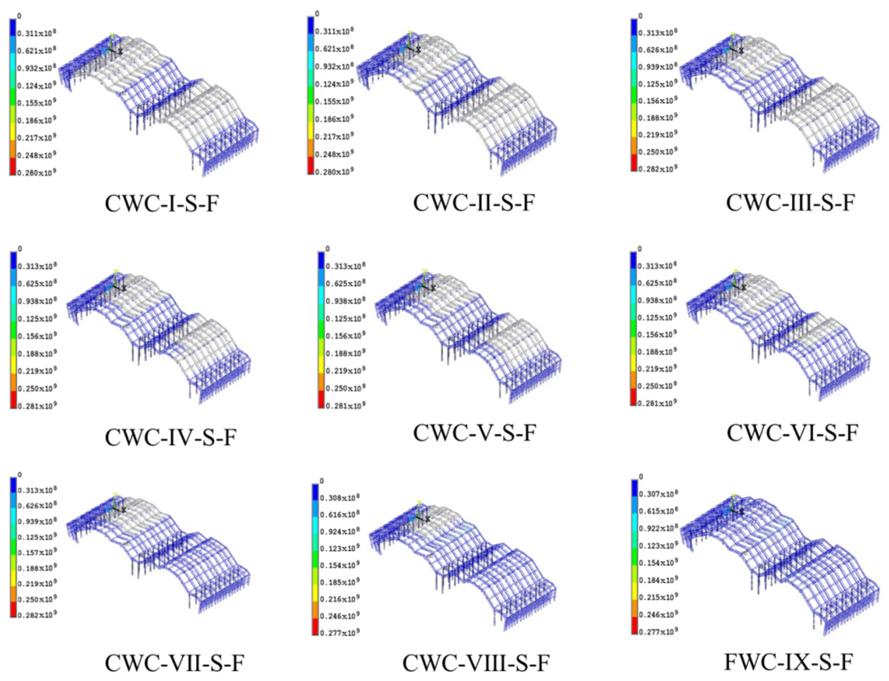
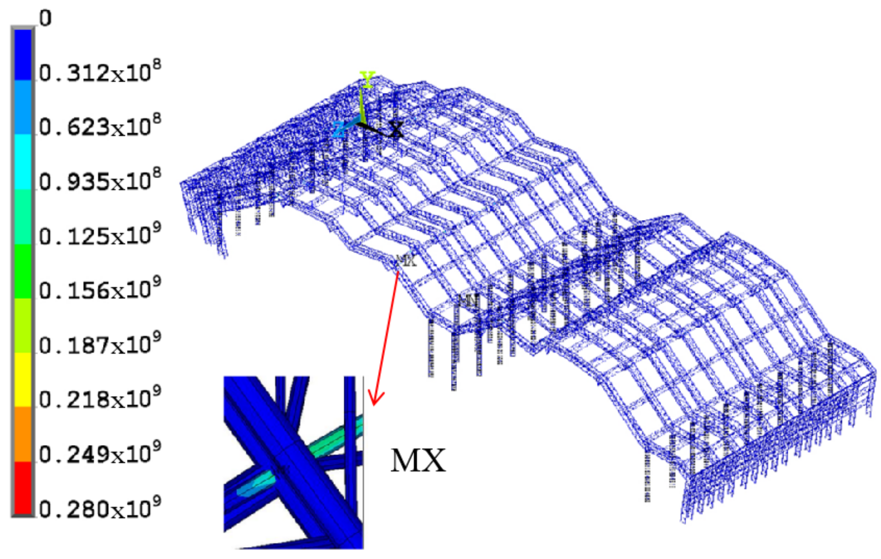
In addition to understanding the maximum stress characteristics of trusses and temporary supports, in order to better understand the overall stress distribution law of the roof structure during the forming process, the finite element analysis software was used to obtain the stress cloud diagrams of each working condition in the structural forming analysis. A stress cloud diagram of various working conditions during the forming process are shown in Figure 11.
The following can be drawn from Figure 11:
- The overall stress value of the large-span steel roof truss structure during the forming process is mostly 0 to 31.1MPa, and the stress value is small. Maximum stress occurs near the support rods and is less than the yield strength of the material. This shows that the support rod has a great influence on the stress of the truss, bears the stress transmitted from the truss, and improves the safety of the construction process.
- During the entire molding process, the maximum stress value is 282 MPa, which occurs in CWC-Ⅲ-S-F and CWC-VII-S-F, and as far as the whole process is concerned, the maximum stress value of CWC-VIII-S-F and FWC-Ⅸ-SF is in the whole. The minimum during the process is 270 MPa. Therefore, the CWC-Ⅲ-S-F and CWC-VII-S-F should be focused on and tested when encountering similar symmetrical long-span steel structures during the construction process.
- During the entire construction process, the maximum stress values all appeared in the same position, all near the temporary supports, and the maximum stress maximum change range is 1.77%, and the average change range is 0.398%. The stress changes smoothly during the construction process, all less than the yield strength of the material. This shows that the average stress of the structure during the whole construction process is relatively stable and the construction is safe.
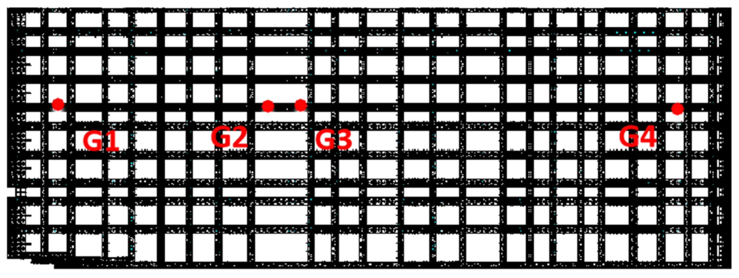
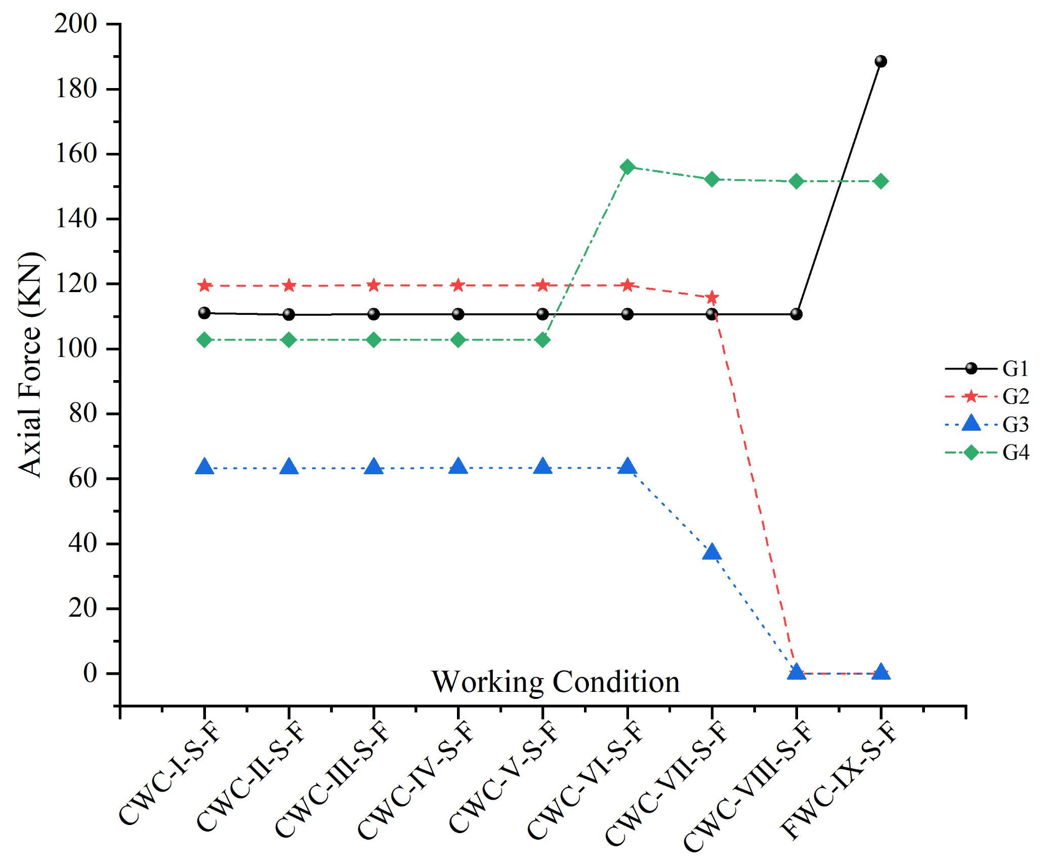
In the forming process of a time-varying structure, in addition to grasping the change of the spatial maximum value and the overall stress distribution law, it is also necessary to understand the time history response of the overall structure. For the internal force response of the forming process, the temporary support only uses the compression rod as the component connecting the roof truss and the temporary support, and the internal force change can better reflect the internal force change of the structural system. Therefore, four compression bars are selected for axial force tracking, numbered G1, G2, G3, and G4, and the four compression bars are located under the same main truss. The positions are shown in Figure 12. Figure 13 shows the time history curve of the internal force at the tracking point during the forming process.
The following can be drawn from Figure 13:
- The cross-influence between working conditions has a certain scope of influence, and the construction of adjacent structures has a great impact. In the early stage, only the axial force of the pressing rod changed around 110 KN, 120 KN, 63 KN, and 102 KN, and the change curve is gentle. This shows that the early construction period is concentrated on the three-prong main truss on the front side of the roof, which is far away from the axial force tracking point. Later, as the trusses of adjacent working conditions are connected in place, the axial force changes greatly, concentrated in CWC-Ⅵ-S-F to FWC-Ⅸ-S-F.
- The change of the axial force of the temporary support only pressure rod is related to the redistribution of internal force caused by the time change of the structure. The G1 and G4 rods increase in axial force in the later stage, while the G2 and G3 rods experience CWC-VII-S-F and CWC-VIII-S-F; the axial force drops to zero. This shows that the truss sections on the left and right sides of G3 and G4 are activated at CWC-VII-S-F and CWC-VIII-S-F (corresponding to the actual in-situ connection of the project). Taking into account the symmetry of the structure, the restraint on both sides of the middle truss section is strengthened, and the downward concentrated force or the moment that causes the upper chord to be pulled causes the middle truss section to deform upward.
6.2. Deformation Process Analysis of the Step-By-Step Construction Process
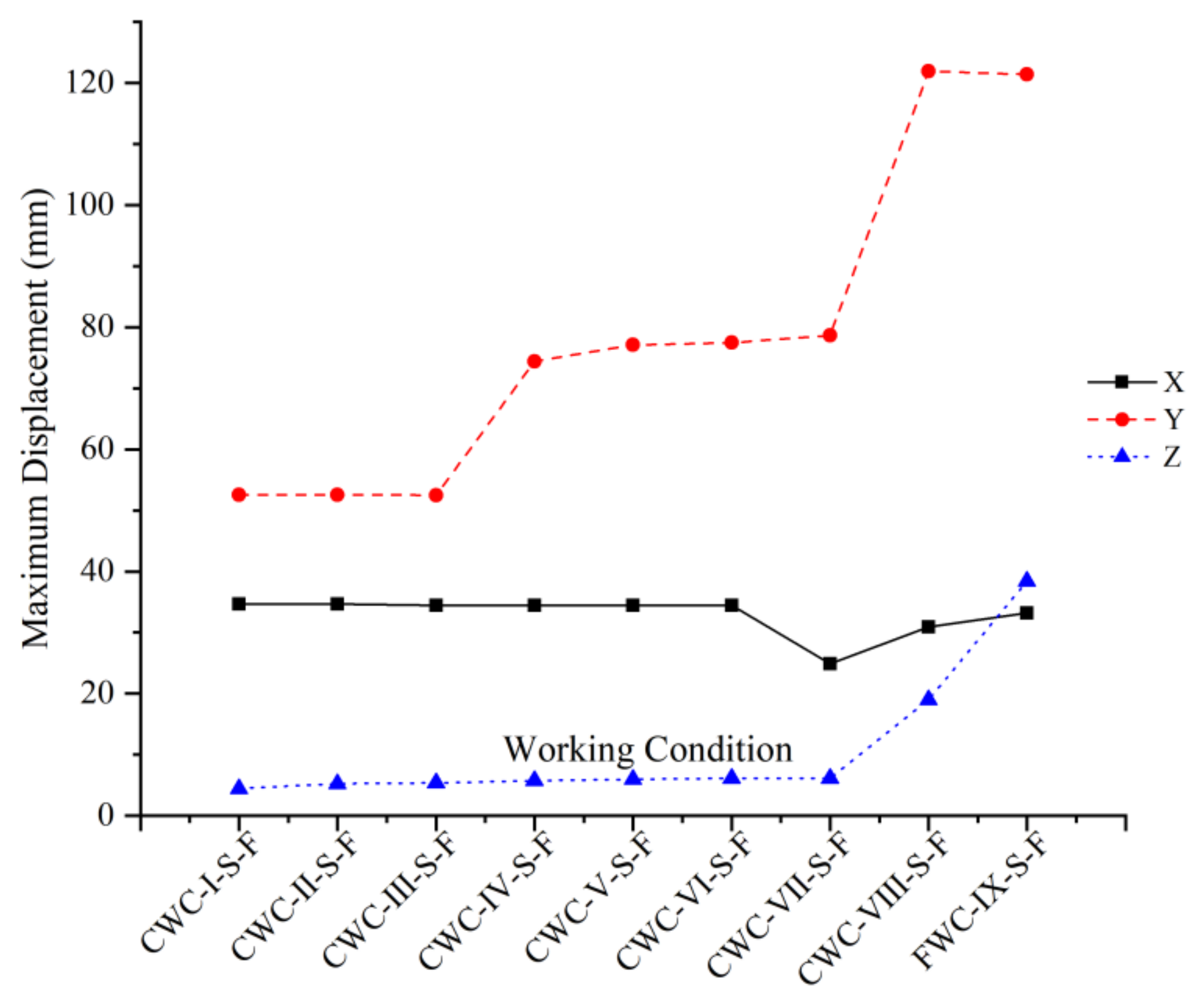
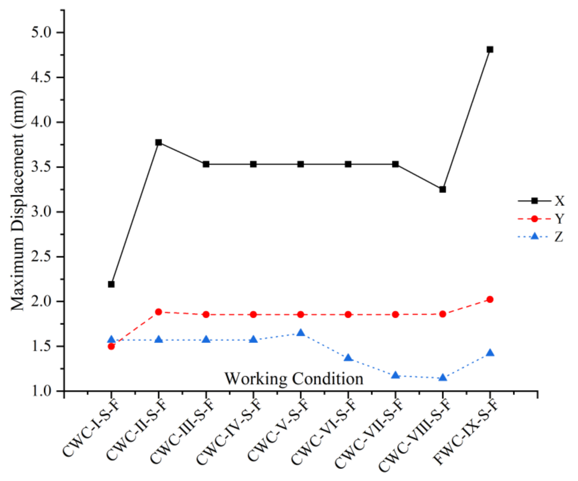
In the construction process, in addition to analyzing the stress characteristics of the structure, the displacement characteristics of the structure have a great influence on the construction safety and the use of the structure, so it is necessary to analyze the deformation of the structure. The life-death element method is used to continuously activate the components, and the maximum value of the roof truss displacement of the corresponding working condition at each time point and the maximum value of the temporary support displacement are obtained through finite element calculation. Figure 14 and Figure 15 show the corresponding displacement time history curves.
The following can be drawn from the displacement time history curve:
- During the roof forming process, the truss deformation is large, while the temporary support deformation is relatively small. The maximum vertical displacement of the truss structure is 121.400 mm, and the maximum X direction displacement of the temporary support is only 4% of the truss displacement. This indicates that the temporary support performance of the standard section of the tower crane is stable and can ensure the stability and safety of the truss forming process.
- The vertical Y direction displacement dominates the truss displacement, while the X direction deformation is the main temporary support. The maximum displacement in the Y direction of the truss is 3.5 and 3.2 times in the X and Z directions, respectively, and the maximum displacement in the X direction of the temporary support is 2.4 and 2.9 times in the Y and Z directions, respectively. The main reason is related to the low lateral flexural rigidity of the structure and the large axial compressive rigidity. It is necessary to prevent the instability of the temporary support in the X direction.
- With the continuous shaping of the structure, the vertical deformation of the truss grows in steps. It changes greatly in CWC-Ⅳ-S-F and CWC-VIII-S-F. The growth point corresponds to the larger construction steps of the cantilever section before the partial or overall closure of the structure. The main reason is that the symmetrical structure requires high structural integrity, and the structure at this time is not complete and the integrity is poor.
- The change stage of the maximum displacement of the temporary support is different from that of the truss. The temporary support has a large sudden change in the early and late stages of the project, and the mid-term structural deformation changes more gently. The truss section corresponding to the two sudden deformation changes belongs to the same group of temporary supports. The reason is related to the large lifting unit of the structure at the span.
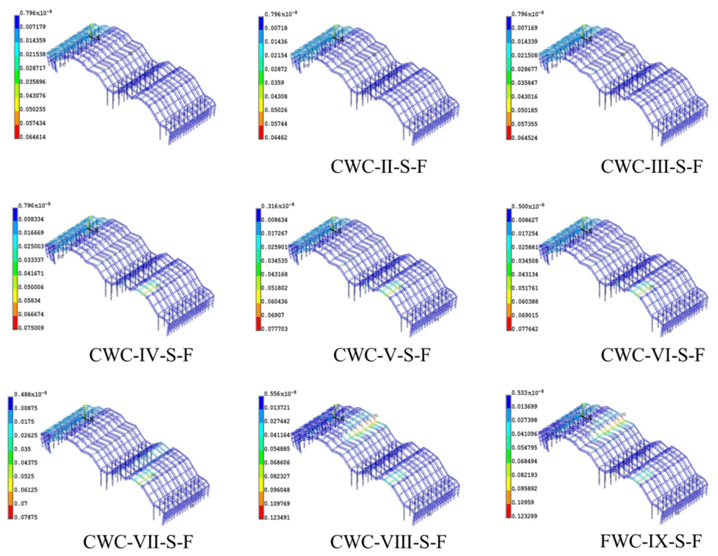
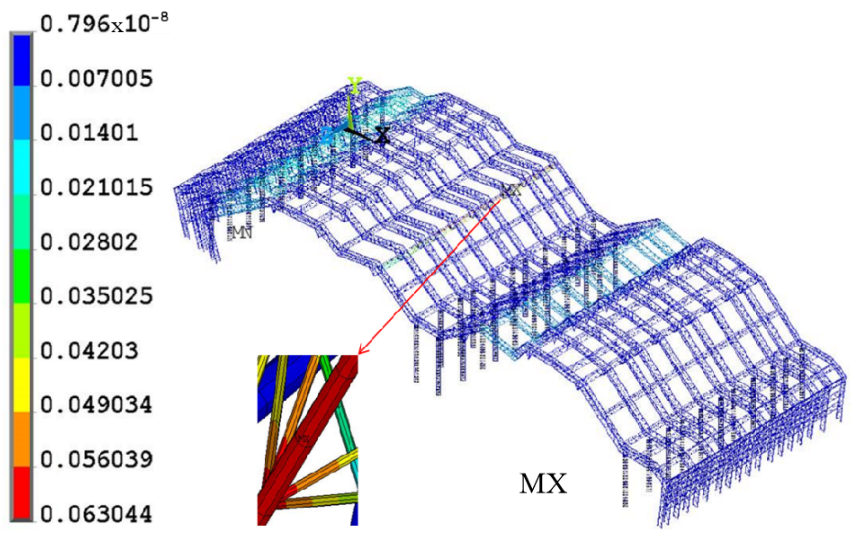
During the construction process, the incomplete structure will undergo large lateral deformation due to the weaker restraint. In order to ensure the safety of the construction process and the quality of structure formation, a structural analysis method that considers the construction process should be adopted to obtain structural response characteristics that are closer to reality. In order to analyze the deformation distribution evolution characteristics of the structure-forming process and the overall strain distribution of each working condition, the finite element life-death element method is used to obtain the displacement cloud diagram of each working condition according to the construction process forming analysis, as shown in Figure 16.
According to the displacement cloud map in Figure 16, it can be found that:
- During the structural forming process, the distribution of structural deformation is constantly changing. The large deformed area gradually shifts from the permanent support of the mid-span and the left side span to CWC-Ⅳ-S-F, CWC-VIII-S-F, CWC-VIII-S-F, and other areas.
- The incomplete structure in the forming process is constantly changing. When the cantilever section is large or the structure is partially or integrally closed, the corresponding truss element deforms greatly. For example, CWC-Ⅰ-S-F and CWC-VIII-S-F are due to the large cantilever section after the hoisting unit is connected in place, while CWC-Ⅳ-S-F, CWC-VII-S-F, and FWC-Ⅸ-S-F are partial or integral close situation.
- Judging from the displacement cloud diagrams of various working conditions, the displacements in most areas of the structure are between 0.00796 mm and 13.7 mm. Except for large local displacements, the maximum displacement in all working conditions is 123 mm, which is within the structural safety range. The maximum displacement values of the first seven working conditions are relatively close, with the maximum change range of 1.6%, the minimum change range of 0.009%, and the average change range of 1.139%, which is relatively stable. The maximum displacement mutation occurred during the construction of CWC-VIII-S-F. At this time, the amplitude of the change reached 56.6%. Until completion of the construction, the maximum displacement occurred at the location of CWC-VIII-S-F, which shows that the similar symmetrical long-span steel structure when the construction progresses to CWC-VIII-S-F, attention should be paid to detecting the displacement of the structure at this time to ensure the safety of construction.
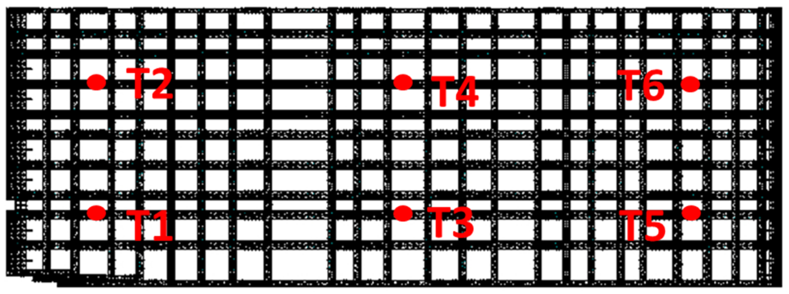
In order to grasp the time history response of the roof structure deformation, comprehensively considering the sequence of flow construction, six nodes of the tracking points are selected for the post-processing analysis of the displacement time history on the third and the eighth. The positions of these six points are in the mid-span and both side-spans, and they are all activated in CWC-Ⅰ-S-F, which can fully meet the needs of the whole process of construction tracking. The coordinates of these six points are shown in Table 4, and the positions are shown in Figure 17.
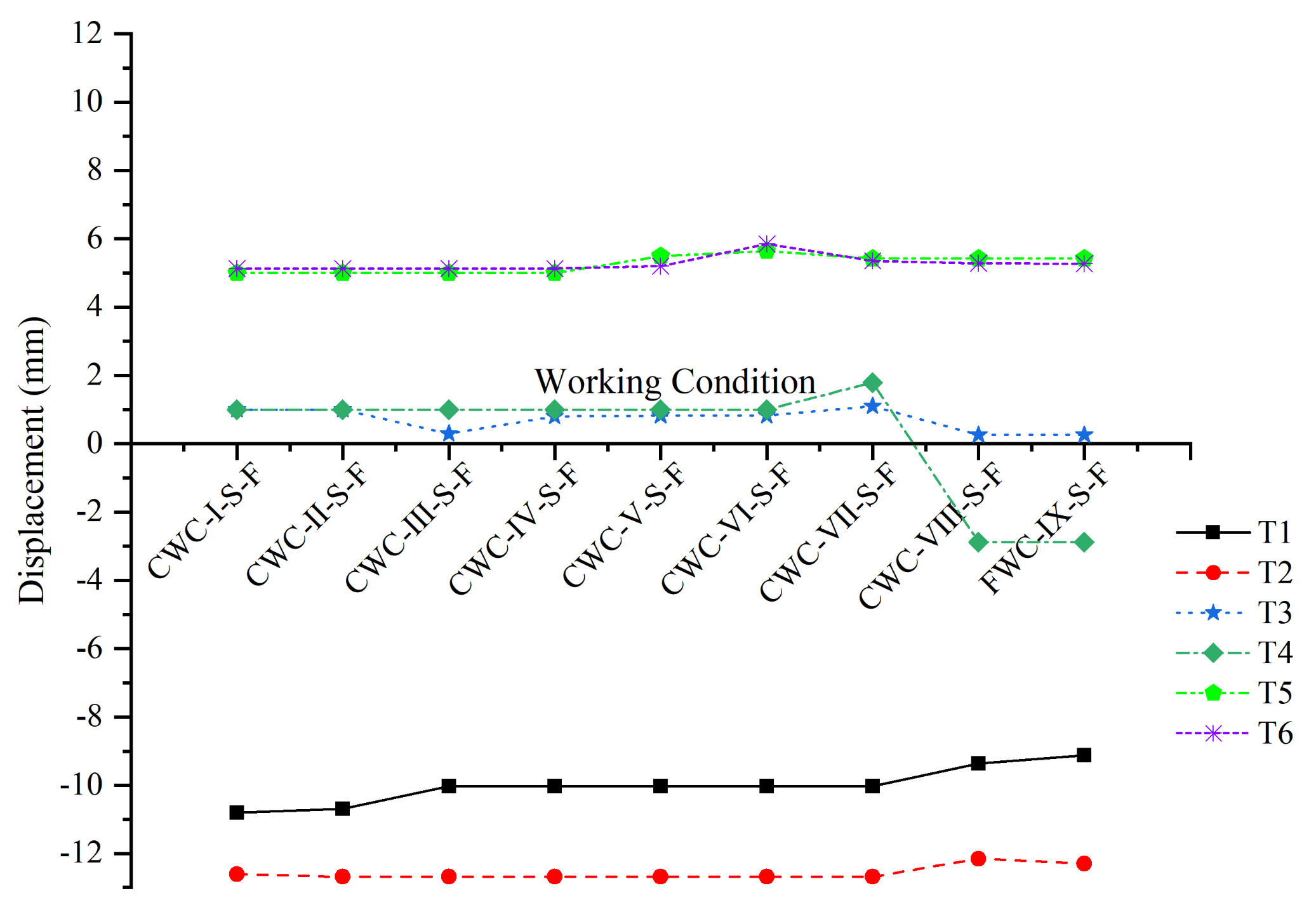
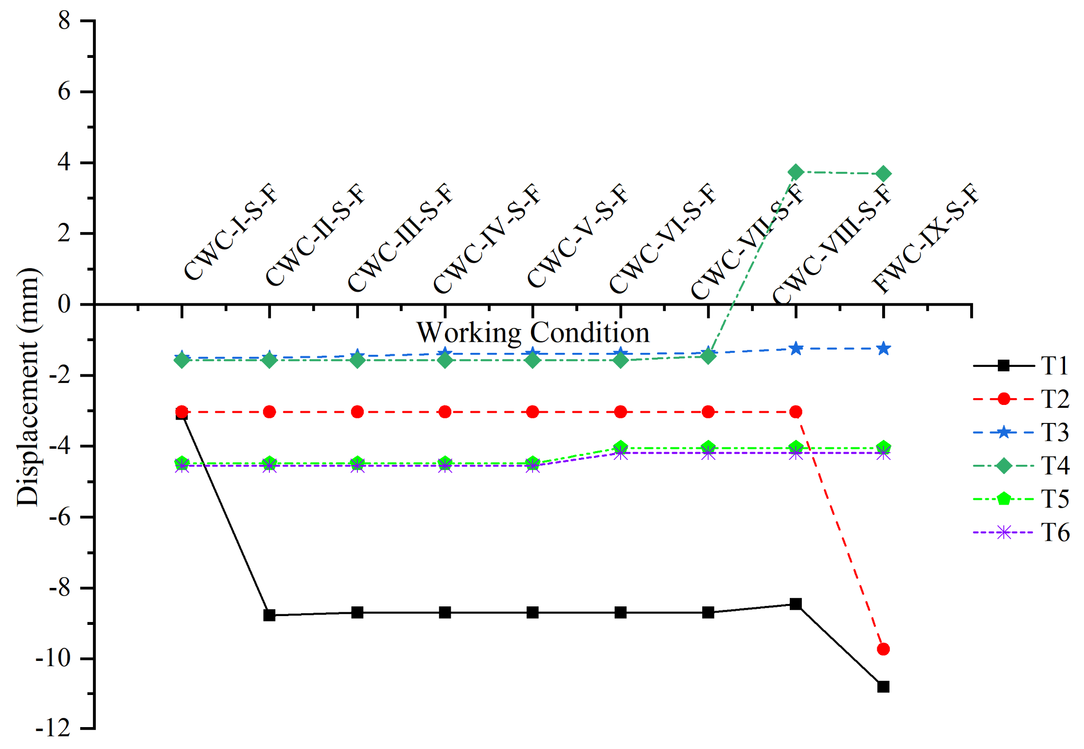
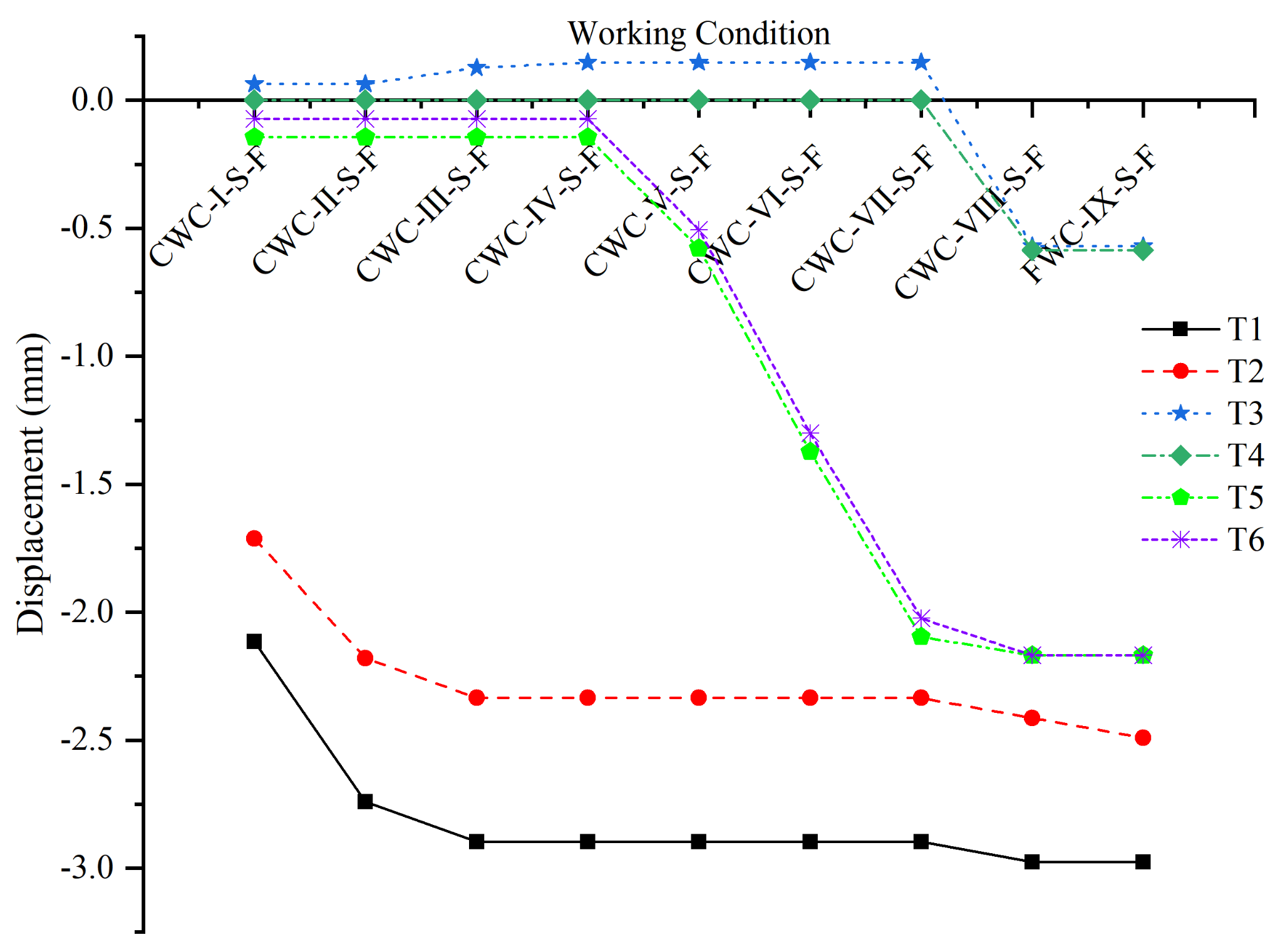
The displacement values of the tracking points T1~T6 in each direction are extracted during the construction process, and the positive and negative signs are kept to represent the deformation direction of the structure; the changing trend is shown in Figure 18, Figure 19 and Figure 20.
- The time-varying characteristics of the structure determine the direction of the maximum deformation response during the forming process. In the truss section where the points T1, T2, T5, and T6 are activated for the first time, it is similar to a cantilevered steel frame structure, and the tracking points are mainly longitudinal (X direction) displacement; the truss section at points T3 and T4 is a horizontally simply supported structure, and the structure is mainly vertical deformation.
- The mutual influence range between the structural forming sequence and the working conditions determines the deformation development law of the truss. The two tracking points T1 and T2 are located at different Z-coordinates on the same truss zone, and there is a surge phase in the Y direction deformation curve, but the surge has inconsistent construction steps. The main reason is that during CWC-Ⅱ-S-F, the construction truss is connected to the main truss at point T1, and the structure at point T1 is deformed to a position close to the final state. In FWC-Ⅸ-S-F, the corresponding truss construction section is connected to the truss at point T2. At this time, the structure at point T2 is deformed sharply and reaches the final deformed state. FWC-Ⅸ-S-F is the last step of the construction process, the structure of the T1 point is also affected, and the vertical displacement is slightly increased. The same deformation law exists for the other tracking points.
- The structural deformation is reversed during the forming process, and the main reason is the change of the structural form. As shown in the displacement curve of the T4 point, in CWC-VIII-S-F, the longitudinal, lateral, and vertical displacements have all changed signs, that is, the structural deformation changes the direction. Before CWC-VII-S-F, the truss elements on the left and right sides of the truss section where T4 is located are not activated. In CWC-VII-S-F and CWC-VIII-S-F, the trusses on the right and left sides are respectively formed in place, and the truss section where T4 has located. The restraint on both sides is strengthened and subjected to a larger reverse bending moment, so that the deformation of the truss changes from downward deflection to upward arch, and the vertical displacement of the tracking point is reversed. The longitudinal and transverse (Z direction) displacement changes of the tracking points are mainly caused by changes in structural form and changes in stiffness distribution as the structure improves.
- As far as the displacement in the x-direction is concerned, the displacements of points T3 and T4 on the mid-span are relatively the smallest in each working condition. On the other hand, the displacements of the four points on the side span are larger than those of the mid-span, except for point T4. The displacement of the other points outside changes relatively stable during the construction process, and the direction of change is also consistent. However, the displacement of the T4 point is reversely abrupt when CWC-VIII-S-F, this is mainly because CWC-VIII-S-F is constructed under the working condition of T4, so that the influence of path effect is reflected in the displacement change of the T4 point, locally caused by changes in stiffness.
- The displacement direction of each point in the Y direction is almost the same. The absolute value of the displacement in the Y direction of T1 and T2 is greater than that of the other points. The displacement of the three points T3, T5, and T6 changes smoothly during the construction process. Compared with these three points, the other points all have displacement mutations in CWC-VIII-S-F and FWC-IX-S-F. The reason for the sudden change of T4 is that after the construction of CWC-VIII-S-F, the constraints around T4 increase, the reverse bending moment increases, and the stiffness increases. However, T1 and T2 are all mutations in FWC-IX-S-F. The main reason is that the construction of FWC-IX-S-F leads to the enhancement of the integrity of the symmetrical structure, and the connection position is at the location of T1 and T2.
- The displacement of each point in the Z direction changes greatly during the construction process, especially the two tracking points T5 and T6, which change sharply from CWC-V-S-F to CWC-VII-S-F. This is because CWC-V-S-F to CWC-VII-S-F is all constructed near these two points, which leads to changes in structural constraints and rigidity. At the same time, reverse bending moments are generated, and the two points T3 and T4 are affected. As a result, the displacement change in the Z direction relative to the X and Y directions is large.
6.3. Analysis of Stress and Strain in the One-Time Forming Process
In order to draw a conclusion from the comparative analysis, the roof and temporary support system were analyzed separately. The following data is obtained through a molding analysis: the maximum equivalent stress of the truss is 280.389 MPa, and the maximum equivalent stress of the temporary support is 20.264 MPa, which is close to the analysis result of the life-death element method considering the forming process, and there is not much difference between the two. At the same time, it is concluded that the displacements of the roof truss in the X, Y, and Z directions are 33.392 mm, 51.716 mm, and 4.852 mm, respectively. The displacements of the temporary support in the X, Y, and Z directions are 0.764 mm, 1.746 mm, and 1.011 mm, respectively. Comparing Figure 13 and Figure 14 for step-by-step molding, it is obvious that:
- One-time forming analysis will underestimate the deformation of the truss and temporary support when the truss is actually formed. The analysis results of the life-death element method considering the forming process are quite different from the results of a modeling analysis. The truss displacement and temporary support displacements of the forming analysis are smaller than the final state of the forming analysis considering the construction process. The maximum vertical displacement of the truss, including the influence of the construction path effect, is 2.3 times that of the one-time forming analysis. Therefore, a forming analysis underestimates the final deformation of the structure.
- During the construction process, the incomplete structure will undergo large lateral deformation due to the weaker restraint. The lateral (Z direction) deformation of the truss is relatively small in the analysis result of one-step forming, which is only 13.0% of the final lateral deformation of the analysis considering the construction process. In order to ensure the safety of the construction process and the quality of structure formation, a structural analysis method that considers the construction process should be adopted to obtain structural response characteristics that are closer to reality.
For further comparison and analysis, finite element software was used to simulate the stress cloud diagram and displacement cloud diagram of the structure during a molding process, as shown in Figure 21 and Figure 22.
- Consider that the overall difference between the stress distribution during the construction process and the one-time forming stress distribution is small.
- The displacement distribution of a forming analysis is inconsistent with the final result of the forming analysis of the construction process. This shows that there is not only the order of loading but also the order of formation of the structure in the structure forming analysis. If the material has nonlinearity or considers path-related factors such as geometric nonlinearity and state nonlinearity, these path-related factors in the structural analysis will be coupled with the time-varying structure. In the end, different construction sequences will be different, and the stress state of the structure will be different.
- In the analysis of structural mechanics based on the theory of small deformation, the step-by-step loading of an elastic structure is often equal to one-step loading, that is, the effect of structural performance caused by the loading sequence of the structure is not considered. However, in the actual process, the next step of loading is carried out based on the previous step’s deformation. In the solution, the stiffness matrix loaded according to the initial state and the stiffness matrix loaded according to the previous step’s deformation state are not the same, and the resulting structural response is also different.
- For long-span steel trusses, the stress of the structure is generally lower than the yield stress of the material, and the constitutive equation satisfies the linear relationship. The material nonlinearity is not considered in the analysis, but the geometric nonlinearity and state nonlinearity cannot be ignored, which makes the construction of large-span complex steel trusses have path effects. Since the internal force generated by the complex long-span steel truss under the weight of the component is relatively large, the complex long-span steel truss is more sensitive to the forming process than the concrete high-rise building. The forming sequence of the truss will have a significant impact on the internal force of the structure under its own weight.
7. Conclusions
During the construction process, the structure is in an incomplete state and the reliability is low. The long-span steel truss structure is more sensitive to the construction process, and the final forming state is closely related to the forming process. Relying on actual engineering, this paper uses the finite element to simulate the forming process of a complex long-span spatial steel truss. The main conclusions are as follows:
- There is a path effect in the structure forming process. In the forming analysis of complex and large-span steel structures, with geometric nonlinearity and structural time-varying coupling analysis, the construction sequence is different, and the structure process and the final stress and deformation size and distribution are also different. It is suggested that finite element software should be reasonably used to simulate the construction process before construction to minimize the influence of the path effects.
- The structural response considering the construction process is significantly greater than the one-time forming analysis without considering the forming process. The main reason is that there are weak loops in the time-varying structure and the gradual accumulation of structural deformation, resulting in a large difference between the resulting state and the design state. This considers that the analysis of the construction process is closer to the actual project.
- During the forming process of the structure, the overall stress level is relatively low, the deformation is relatively large, and the construction process analysis problem of the broken-line-shaped complex long-span steel truss belongs to the problem of small strain and large displacement. Therefore, it is recommended to pay attention to the impact of displacement when carrying out the construction of large-span steel structures.
- The stress and deformation continue to redistribute as the structure is formed, the maximum response change does not increase all the time, and the structure deformation may also be reversed, which indicates that the structure deformation is mainly related to the structural form before and after the structural time change.
- During the forming process, the maximum response size and change range of the truss is obviously larger than that of the temporary support. The temporary support can play its supporting role well, and the roof truss has a larger response. It is recommended to pay more attention to the displacement and stress response of the truss when it encounters a similar symmetrical long-span steel structure truss in-place of the forming construction.
- The cross-effects of the construction steps have a certain range of influence, and the construction of adjacent structures has a great impact. It is recommended to pay close attention to the influence of the forming of the truss section on the adjacent structure during the construction process. Taking into account the symmetry of the project, it is necessary to pay more attention to the symmetrical large-span spatial steel truss structure.
Author Contributions
Conceptualization, G.Y. and Y.Y.; methodology, G.Y.; software, C.W.; validation, G.Y., Y.Y. and C.W.; formal analysis, C.W.; investigation, Y.Y.; resources, Y.Y.; data curation, Y.Y.; writing—original draft preparation, C.W.; writing—review and editing, Y.Y. All authors have read and agreed to the published version of the manuscript.
Funding
This work was funded by the National Key R&D Program of the Ministry of Science and Technology (No. 2019YFD1101005-4), Fundamental Research Funds for the Central Universities (No. 2020CDJQY-A067), and the 111 project of the Ministry of Education and the Bureau of Foreign Experts of China (No. B18062).
Institutional Review Board Statement
Not applicable.
Informed Consent Statement
Not applicable.
Data Availability Statement
Please contact the corresponding author.
Conflicts of Interest
The authors declare no conflict of interest.
References
- Li, P.C.; Wang, H. A novel strategy for the crossarm length optimization of PSSCs based on multi-dimensional global optimization algorithms. Eng. Struct. 2021, 238, 112238. [Google Scholar] [CrossRef]
- Lee, S.H.; Lee, K.K.; Woo, S.S.; Cho, S.H. Global vertical mode vibrations due to human group rhythmic movement in a 39 story building structure. Eng. Struct. 2013, 57, 296–305. [Google Scholar] [CrossRef]
- Yu, F.B.; Wang, X.T.; Zhou, M.; Wang, W.Z. Research on Fire Resistance Performance of Pre-Stressed Suspended Steel Reticulated Shell. Adv. Struct. 2011, 163–167, 790–794. [Google Scholar] [CrossRef]
- Chen, J.; Ma, K.J.; Xiao, J.C.; Wei, Y.H.; Chen, H.N.; Lu, Y.Q. Prefabricated construction process and unloading monitoring of space steel grid cassettle structuremulti-storey large-span gymnasium. Int. J. Electr. Eng. Educ. 2021. [Google Scholar] [CrossRef]
- Yin, X.J.; Xu, Z.D.; Yang, Y.; Luo, Y.; Wang, J.L. Human-Induced Vibration Control with TMDs for Guangzhou Asian Games Comprehensive Museum. Int. J. Acoust. Vib. 2019, 24, 736–743. [Google Scholar] [CrossRef]
- Chen, D.S.; Xu, W.C.; Qian, H.L.; Sun, J.Y.; Li, J.F. Effects of non-uniform temperature on closure construction of spatial truss structure. J. Build. Eng. 2020, 32, 101532. [Google Scholar] [CrossRef]
- Luo, Y.F.; Ye, Z.W.; Guo, X.N.; Qiang, X.H.; Chen, X.M. Data Missing Mechanism and Missing Data Real-Time Processing Methods in the Construction Monitoring of Steel Structures. Adv. Struct. Eng. 2015, 18, 585–601. [Google Scholar] [CrossRef]
- Zhou, M.; Fan, J.S.; Liu, Y.F.; Zhang, J.X.; Duan, X.J.; Lei, S.S. Non-uniform temperature field and effect on construction of large-span steel structures. Autom. Constr. 2020, 119, 103339. [Google Scholar] [CrossRef]
- Li, C.B.; Wang, L.N.; Weng, Y.M.; Qin, P.J.; Li, G.J. Nonlinear Analysis of Steel Structure Bent Frame Column Bearing Transverse Concentrated Force at the Top in Factory Buildings. Metals 2020, 10, 1664. [Google Scholar] [CrossRef]
- Yang, Y.; Cheng, Q.; Zhu, Y.H.; Wang, L.L.; Jin, R.Y. Feasibility Study of Tractor-Test Vehicle Technique for Practical Structural Condition Assessment of Beam-Like Bridge Deck. Remote Sens. 2020, 12, 114. [Google Scholar] [CrossRef] [Green Version]
- Jakubowski, J.; Fiolek, P. Evaluation of Stiffness and Dynamic Properties of a Mine Shaft Steelwork Structure through In Situ Tests and Numerical Simulations. Energies 2021, 14, 664. [Google Scholar] [CrossRef]
- Jiansinlapadamrong, C.; Park, K.; Hooper, J.; Chao, S.H. Seismic Design and Performance Evaluation of Long-Span Special Truss Moment Frames. J. Struct. Eng. 2019, 145, 04019053. [Google Scholar] [CrossRef]
- Sanches, R.; Tao, J.J.; Fathieh, A.; Mercan, O. Investigation of the seismic performance of braced low-, mid- and high-rise modular steel building prototypes. Eng. Struct. 2021, 234, 111986. [Google Scholar] [CrossRef]
- Kumar, R.; Sahoo, D.R. Seismic fragility of steel special truss moment frames with multiple ductile vierendeel panels. Soil Dyn. Earthq. Eng. 2021, 143, 106603. [Google Scholar] [CrossRef]
- Yang, Y.; Yang, Y.B.; Chen, Z.X. Seismic damage assessment of RC structures under shaking table tests using the modified direct stiffness calculation method. Eng. Struct. 2017, 131, 574–586. [Google Scholar] [CrossRef]
- Ma, T.T.; Zhao, L.; Chen, N.Y.; Ge, Y.J.; Zhang, D. Wind-induced dynamic performance of a super-large hyperbolic steel-truss cooling tower. Thin-Walled Struct. 2020, 157, 107061. [Google Scholar] [CrossRef]
- Ren, W.; Zhao, J.C. Probabilistic collapse analysis of steel frame structures exposed to fire scenarios. J. Zhejiang Univ. Sci. A 2021, 22, 195–206. [Google Scholar] [CrossRef]
- Wang, F.; Shi, G.J.; Zhai, W.B.; Li, B.; Zhang, C.; Fang, H.Y. Internal Force on and Deformation of Steel Assembled Supporting Structure of Foundation Pit under Thermal Stress. Appl. Sci. 2021, 11, 2225. [Google Scholar] [CrossRef]
- Zhang, G.; Xu, L.H.; Li, Z.X. Development and seismic retrofit of an innovative modular steel structure connection using symmetrical self-centering haunch braces. Eng. Struct. 2021, 229, 111671. [Google Scholar] [CrossRef]
- Ceribasi, S. Reliability of Steel Truss Roof Systems Under Variable Snow Load Profiles. Int. J. Steel Struct. 2020, 20, 567–582. [Google Scholar] [CrossRef]
- Bai, Z.X.; Shen, C.J.; Jiang, Z.Q.; Cheng, K.K.; Wang, H.W. Cyclic loading tests of an earthquake-resilient prefabricated steel frame with open-web steel channel beams. J. Constr. Steel Res. 2021, 177, 106477. [Google Scholar] [CrossRef]
- Ribeiro, P.I.S.; Gomes, A.V.S.; Calenzani, A.F.G. Dynamic Analysis of a Steel Floor System with Dry Slabs Subjected to Vibrations Due to Human Walking. Int. J. Steel Struct. 2020, 20, 969–984. [Google Scholar] [CrossRef]
- Kim, S.; Kim, S.A. Framework for Designing Sustainable Structures through Steel Beam Reuse. Sustainability 2020, 12, 9494. [Google Scholar] [CrossRef]
- Liu, X.L. Fields of Priority Development of Structural Engineering in My Country. China Civ. Eng. J. 1993, 26, 21–28. [Google Scholar]
- Guo, Y.L.; Liu, X.W. Nonlinear Analysis Method of Steel Structure Construction Mechanics State. Eng. Mech. 2008, 10, 19–24. [Google Scholar]
- Zheng, J.; Ge, H.P.; Wang, X.T.; He, Z.; Luo, Y. Local Configuration Constrained Life-Death Element Method and Its Application in Construction Mechanics Analysis. J. Build. Struct. 2012, 33, 1. [Google Scholar]
- Zhang, W.L.; Wu, Z.X.; Chen, B.H. Simulation Study on Construction Process of Complex Spatial Steel Structure Based on the Construction Mechanics. Appl. Mech. Mater. 2012, 2031, 1209–1213. [Google Scholar] [CrossRef]
- Chen, Z.H.; Zhao, Z.W.; Zhu, H.; Wang, X.D.; Yan, X.Y. The step-by-step model technology considering nonlinear effect used for construction simulation analysis. Int. J. Steel Struct. 2015, 15, 271–284. [Google Scholar] [CrossRef]
- Li, M.T.; Ji, P.H. Nonlinear time-varying analysis algorithms for modeling the behavior of complex rigid long-span steel structures during construction processes. Steel Compos. Struct. 2015, 18, 1197–1214. [Google Scholar]
- Zhang, Y.G.; Xue, S.D.; Yang, Q.S.; Fan, F. Large-Span Spatial Structure, 1st ed.; Machinery Industry Press: Beijing, China, 2005; pp. 215–224. [Google Scholar]
- Song, T.X.; Zhou, S.Z.; Yang, W.B. Finite Element Calculation of Nonlinear Structure, 1st ed.; Huazhong University of Science and Technology Press: Wuhan, China, 1996; pp. 58–111. [Google Scholar]
- Wang, X.M.; Li, Y.Q.; Xu, H.W. ANSYS Structural Analysis Unit and Application, 1st ed.; China Communications Press: Beijing, China, 2007; pp. 7–12. [Google Scholar]
- Huang, W.H.; Shao, C.X. Multi-Body System Dynamics; Science Press: Beijing, China, 1996; pp. 74–97. [Google Scholar]
- Yao, G.; Guo, H.T.; Yang, Y.; Xiang, C.M.; Robert, S. Dynamic Characteristics and Time-History Analysis of Hydraulic Climbing Formwork for Seismic Motions. Adv. Civ. Eng. 2021, 2021, 2139153. [Google Scholar]
- Zhang, X.H. Random Subspace Method and Application of Vibration Modal Parameter Identification in Structural Environment. Master’s Thesis, Fuzhou University, Fuzhou, China, 2005. [Google Scholar]
Figure 1.
Research process and method.

Figure 2.
Strain in the plane.

Figure 3.
TWIPP in Chongqing.

Figure 4.
The finite element model.

Figure 5.
Construction section and construction direction.

Figure 6.
Working condition sequence.

Figure 7.
(a–d) The first four modes of a large-span structure.

Figure 8.
Sensor layout.

Figure 9.
Structure frequency and order of random subspace recognition.

Figure 10.
Maximum stress curve during the roof forming process.

Figure 11.
Stress cloud diagram of various working conditions during the forming process (pa).

Figure 12.
Internal force-time history tracking rod position.

Figure 13.
The internal force-time history curve of the tracking point forming process.

Figure 14.
Displacement time history curve of the roof truss.

Figure 15.
Temporary support displacement time history curve.

Figure 16.
Displacement cloud diagram of the forming process of various working conditions (m).

Figure 17.
Tracking point location.

Figure 18.
The displacement time history of the tracking point in the X direction.

Figure 19.
The displacement time history of the tracking point in the Y direction.

Figure 20.
The displacement time history of the tracking point in the Z direction.

Figure 21.
One-time forming stress cloud diagram (pa).

Figure 22.
Displacement cloud diagram of one-time forming (m).


Table 1.
Composition of the working conditions.
| Working Condition | Number of Permanent Supports | Number of Temporary Support | Change |
|---|---|---|---|
| CWC-Ⅰ-S-F | Six | Four | — |
| CWC-Ⅱ-S-F | Six | Four | Unit1 |
| CWC-Ⅲ-S-F | Six | Four | Unit2 |
| CWC-Ⅳ-S-F | Six | Four | Unit3 |
| CWC-Ⅴ-S-F | Six | Four | Unit4 |
| CWC-Ⅵ-S-F | Six | Four | Unit5 |
| CWC-VII-S-F | Six | Four | Unit6 |
| CWC-VIII-S-F | Six | Four | Unit7 |
| FWC-Ⅸ-S-F | Six | Four | Unit8 |
Table 2.
Sectional dimensions of the structural members.
| Section Name | S1 | S2 | S3 | S4 | S5 | S6 | S7 | S8 |
|---|---|---|---|---|---|---|---|---|
| Section size (mm) | Φ299 × 8 | Φ89 × 5 | Φ114 × 5 | Φ273 × 6 | Φ180 × 6 | Φ140 × 5 | Φ76 × 5 | Φ245 × 8 |
| Steel model | Q345 | Q345 | Q345 | Q345 | Q345 | Q345 | Q345 | Q345 |
| Component type | Round steel pipe | Round steel pipe | Round steel pipe | Round steel pipe | Round steel pipe | Round steel pipe | Round steel pipe | Round steel pipe |
Table 3.
Comparison between model results and actual measurement results.
| Mode | Natural Frequency (Hz) | Deviation | |
|---|---|---|---|
| Numerical Calculation | Actual Measurement | ||
| 1 | 0.8461 | 0.8726 | 3.13% |
| 2 | 1.0703 | 1.1005 | 2.817% |
| 3 | 1.4029 | 1.4205 | 1.2578% |
| 4 | 1.4286 | 1.4646 | 2.517% |
Table 4.
Tracking point coordinates.
| Tracking Point | X | Y | Z |
|---|---|---|---|
| T1 | 30.461 | 30.615 | 82.000 |
| T2 | 30.461 | 30.615 | 30.000 |
| T3 | 157.087 | 29.562 | 82.000 |
| T4 | 187.087 | 29.562 | 30.000 |
| T5 | 292.675 | 26.893 | 82.000 |
| T6 | 292.675 | 26.893 | 30.00 |
Publisher’s Note: MDPI stays neutral with regard to jurisdictional claims in published maps and institutional affiliations. |
© 2021 by the authors. Licensee MDPI, Basel, Switzerland. This article is an open access article distributed under the terms and conditions of the Creative Commons Attribution (CC BY) license (https://creativecommons.org/licenses/by/4.0/).
Share and Cite
MDPI and ACS Style
Yao, G.; Wu, C.; Yang, Y. Scientometric Analysis for Mechanical Performance of Broken-Line Long-Span Steel Structure in Construction Considering Geometric Nonlinearity. Symmetry 2021, 13, 1229. https://doi.org/10.3390/sym13071229
AMA Style
Yao G, Wu C, Yang Y. Scientometric Analysis for Mechanical Performance of Broken-Line Long-Span Steel Structure in Construction Considering Geometric Nonlinearity. Symmetry. 2021; 13(7):1229. https://doi.org/10.3390/sym13071229
Chicago/Turabian StyleYao, Gang, Chaoyu Wu, and Yang Yang. 2021. "Scientometric Analysis for Mechanical Performance of Broken-Line Long-Span Steel Structure in Construction Considering Geometric Nonlinearity" Symmetry 13, no. 7: 1229. https://doi.org/10.3390/sym13071229
Note that from the first issue of 2016, this journal uses article numbers instead of page numbers. See further details here.