Spontaneous and Stimulated Undulator Radiation in Symmetric and Asymmetric Multi-Periodic Magnetic Fields

Department of Theoretical Physics, Faculty of Physics, M. V. Lomonosov Moscow State University, 119991 Moscow, Russia
*
Author to whom correspondence should be addressed.
Symmetry 2021, 13(1), 135; https://doi.org/10.3390/sym13010135
Submission received: 16 December 2020
/
Revised: 7 January 2021
/
Accepted: 12 January 2021
/
Published: 15 January 2021
(This article belongs to the Special Issue Advances in Synchrotron and Undulator Radiation Studies)
Abstract
:In this work, the radiation from electrons in multi-periodic undulator fields with symmetric and asymmetric harmonics was analyzed using generalized Bessel functions formalism. The asymmetric, symmetric, and anti-symmetric periodic magnetic fields with harmonics were studied in order to get the enhanced radiation of the high harmonics of undulator radiation (UR). The effect on the spontaneous and stimulated UR was explored. The exact integral forms for the Bessel coefficients were obtained for undulators with general symmetric and asymmetric field harmonics. Spectral properties of the radiation from several configurations of the undulator fields with harmonics were compared with each other. The resulting spontaneous UR spectrum and harmonic intensities were obtained analytically in the form of integrals and compared with the respective results that were obtained numerically with SPECTRA program. The dimensionless scaling parameter of a free electron laser (FEL)—the Pierce parameter (ρ)—was computed and compared for the different considered undulators. We studied the differences in the behavior of the high-gain single pass FEL harmonics and the spontaneous UR harmonics in the same undulators. The undulators with variable deflection parameter (k) were considered. The effect of the k parameter (deflection parameter for a common planar undulator) on the spontaneous UR and on the high-gain FEL radiation was explored. In this context, an experiment with variable strength undulators at FLASH 2 FEL was analyzed; the shorter saturated length in high harmonic self-seeding (HHSS) regime vs. self-amplified spontaneous emission (SASE) is explained.
1. Introduction
The synchrotron radiation (SR) from electrons was predicted and discovered in the middle of the 20th century [1]. It was followed by the prediction [2] of undulator radiation (UR), which is in fact the SR from relativistic charges in a spatially periodic magnetic field. Both SR and UR are incoherent. Motz built an undulator where UR was produced [3] and, by developing the ideas of Ginzburg, theoretically demonstrated that electrons, grouped in microbunches, can radiate coherently [4]. The coherent radiation is generated in undulators of free electron lasers (FELs) upon the interaction of the radiation with electrons. A theory of interaction between the radiation and the electrons in undulators was developed by Madey [5]. In an FEL, the Lorenz force of the wave field pushes towards the nods of the electromagnetic wave electrons, which are behind or ahead of the nods; in this way, the FEL forms microbunches, separated by the wavelength of the radiation. Moreover, the radiation of the fundamental frequency in an FEL also induces microbunching at the wavelength of the harmonics of the fundamental frequency, although to weaker extent. The emission and gain of FEL harmonics were first calculated in [6,7]. The radiation from microbunches is largely coherent, as already suggested by Ginzburg in 1947 [2]. At the present stage of development of radiation sources, FELs have extended to hard X-ray bands; their radiation bursts have ultra-short femtosecond lengths. Interest in theoretical studies of SR and UR is largely determined by their applications in FELs [8,9,10,11] and their improvements. In fact, X-ray FELs are huge installations that require high-energy electron sources with very high quality beams; this makes their construction and operation expensive. Using the radiation of harmonics can help to reduce FEL size and the required energy of the electron beam. Harmonic seeding and self-seeding can help to improve the stability and time coherence of a self-amplified spontaneous emission (SASE) FEL. Theoretical aspects of FEL operation and FEL characteristics were reviewed, for example, in [12,13,14,15,16,17,18,19,20]. An accurate description of the spontaneous UR intensity in an undulator can be done with the generalized Bessel and Airy functions; they account for the main loss factors for each UR harmonic. The description of FEL radiation is usually done numerically, since it requires the solution of huge number of equations for the electron motion and interaction with the wave. The phenomenological description of FEL power evolution [21,22,23,24,25] involves simple analytical formulae and gives close-to-reality predictions with just a personal computer and a standard set of programs or even an engineering calculator; it does not need programmers, special software, and trained personnel. The phenomenological description of an FEL is based on an accurate analytical description of spontaneous UR from an undulator and Bessel factors that individually account for all main losses for each harmonic.
The effect of field harmonics on UR in multi-periodic magnetic fields has been studied in many works, e.g., recently in [26,27,28,29,30,31,32,33,34,35,36,37,38,39,40] and earlier in [41,42,43,44]; however, results have sometimes been contradictive and even controversial. Moreover, we noticed misprints in some earlier works that involved cumbersome analytical calculations for the radiation from undulators with field harmonics [28,32,34,40].
The authors of [45] proposed the valuable conclusion that an optimal undulator field for the linearly polarized monochromatic radiation can be composed of the first and third harmonics of the magnetic field. Making use of this idea, we reviewed many common configurations of magnetic fields in undulators and their resulting radiation patterns. We also studied general configurations of magnetic fields in undulators with field harmonics in order to individuate the fields, as is favorable for harmonic radiation. In the context of FEL applications, especially in the cascaded FELs with harmonic multiplication, it is useful to have UR harmonics enhanced and the fundamental tone possibly weakened at the same time. Spontaneous and stimulated UR was explored in undulators with a variable k parameter (deflection parameter for a common planar undulator). The effect of the latter on the amplification of harmonics was studied. UR intensity and Bessel factors were calculated analytically using the formalism of generalized Bessel and Airy functions, which accounts for the field harmonics, losses, and distortions by non-periodic magnetic components. Analytical tools usually allow for the deep analysis and understanding of the underlying physical reasons for the behavior of a system, while numerical tools often provide the advantage of giving precise evaluations of most complex mathematical problems that cannot be solved analytically. We compared the numerical and analytical results for the studied undulators, and we explored the harmonic multiplication in the cascaded undulators, where the last cascades were tuned to the harmonics of the first. The results were applied to the modeling of the stimulated radiation in a cascaded, single-pass, high-gain FEL. We considered real beams with all major loss factors, such as the energy spread and emittance.
The main aim of the paper was to identify the undulator fields that allow for enhanced harmonic generation at the shortest possible wavelength. The paper focused on applications for such undulators in X-ray FELs with SASE and cascaded harmonic multiplication. High harmonic amplification at a shorter wavelength allows for shorter FELs, lower beam energy, lower costs. A FLASH 2 FEL experiment with harmonic multiplication was analyzed.
2. Numerical Approach to UR Calculations with the SPECTRA Code
The numerical treatment of UR can be done with the SPECTRA code; the details of the program were given in [46,47,48,49]. The program calculates the photon brightness, spectral and angular distribution, the total flux of photons, etc. The equations in [46] described the differential density of the radiated photons dNp or the radiated power dP per unit of surface dS in a relative spectral interval dω/ω through the following convolution [46]:
where ω1 is the fundamental UR frequency and N is the number of undulator periods;
where is the flux density for an infinite number of periods, which reads as follows [46]:
where λu is the undulator period, φ is the polar angle and [46]
where and are the horizontal and vertical beam sizes, respectively; γ is the Lorentz factor; c is the speed of light; is the fine structure constant; is the velocity of an electron; ; is the retarded time; , , is the vector from an electron to the observer; ; and . The effect of the energy spread and finite beam emittance is described as a beam envelope at the position of observation. Both horizontal and vertical beam envelopes are calculated in SPECTRA; the emittance is taken into account by a convolution of the single electron radiation with a two-dimensional electron distribution function. The energy spread of the electrons in the beam causes spectral broadening. This is accounted for by a convolution with a Gaussian distribution with an root mean square width , where is the photon energy, E is the electron energy, and σε is the spread. The usual approximation for the radiation studies is the far zone, where and the distance between the electron and the observer is much longer than the undulator size; although it is possible to include near zone in the SPECTRA calculations, this noticeably slows down the process. We use the far zone approximation in what follows.
Integration over the frequencies ω’ in Equation (1) reduces to the convolution with the typical for the UR studies function SN, which allows for a fast Fourier transform algorithm for the convolution. In SPECTRA code, fast oscillating integrands occur, and they must be computed many times for precision. To help with this task, the whole region of integration over the time of the electron motion in the undulator is divided into several sections, within which the functions are approximated by third order polynomials. If the function can be approximated by an n-th order polynomial in the region of integration, then its n-th derivative is constant. By integrating the function by parts n times, we get
Accounting for , the first term in Equation (6) becomes , where is a small interval of time, during which g(t) is well approximated by the third order polynomial. The derivatives up to the third order are determined in SPECTRA by a cubic-spline interpolation method [50]. Thus, the whole integration domain, , consists of m such small intervals of time (see [46]); the integration in G effectively reduces to the summation:
where is the k-th order derivative of .
The above scheme provides fast and accurate numerical results. For the precise integration with finite emittance, the radial and azimuthal integration should be performed; the former is reduced to an energy convolution in SPECTRA. In an energy region of the spectrum where high harmonics dominate, the convolution with the SN of Equation (2) has little effect on the shape of the spectrum. In this case, SPECTRA omits the convolution and saves time without sacrificing accuracy. For our calculations, we used the “Energy Dependence → Angular Flux Density” option, where the above-described integrals were computed. For further details and options of SPECTRA, see [46].
3. Bessel Factors for UR Harmonics in Multiperiodic Magnetic Fields
The simplest though quite good approximation of the periodic magnetic field in a planar undulator is by the pure sinusoidal function: , where H0 is the amplitude of the magnetic field on the undulator axis, directed along z. The above model, complemented by the hyperbolic trigonometric functions (see [51,52]), and , describes the magnetic field in the whole gap between the undulator magnets and satisfies Maxwell equations. The off-axis position of electrons in a finite size beam causes betatron oscillations, the split of the radiation lines, and even UR harmonics on the undulator axis. The even UR harmonics also appear due to the off-axis angles, in which the radiation is viewed in the whole section of the beam, and due to the distortions induced by non-periodic magnetic fields. The above-mentioned effects are known; they have recently been readdressed in the context of multi-harmonic undulators in [52,53,54,55,56,57,58,59,60]. Here, we focused on the effect of the field harmonics on the spontaneous UR and high-gain FEL radiation; we analyzed the radiation harmonic intensities and their Bessel factors. The latter determine the universal scaling FEL parameter, the so-called Pierce parameter [15,16]:
where is the main undulator period (m), J [A/m2] is the current density, γ is the relativistic factor, is the Alfven current constant (A), is the effective undulator parameter that reduces to in common planar undulators, and is the Bessel factor for the n-th UR harmonic. The increase of the Pierce parameter, defined by Equation (8), shortens the FEL gain length, , the saturation length, and the FEL itself. When the fundamental frequency of a FEL saturates, higher harmonics growth terminates, thus reaching its saturated powers (see, for example, [28,29]):
where Pe is the power of the electron beam. Higher values of the Pierce parameter ρ yield stronger amplification of harmonics and less strict requirements to the energy spread in an FEL. To maximize ρ for a given electron current and energy, the value of in Equation (8) can be increased by using special undulators with possibly large Bessel factors fn, or by making an undulator with long period λu and large deflection parameter k. However, the higher the values of λu and k, the longer the UR harmonic resonance wavelength becomes:
where k is the deflection parameter for a common planar undulator and the factor if there are field harmonics (see (13)). The increase of the radiation wavelength can be compensated for by the increase of the relativistic factor γ, but this, in turn, reduces the Pierce parameter of Equation (8) and yields longer gain and saturation. It follows that in any case, it is favorable to have high values of the harmonic Bessel coefficients (fn) for high harmonic powers and their fast growth. Moreover, use of UR harmonics allows for lower electron energy than that needed for the fundamental frequency at the same wavelength. This is particularly important for the X-ray band, where all installation parameters are at their extreme values. The n-th harmonic of spontaneous UR from an undulator with N main periods has the following intensity:
where (see Equation (2)), is the detuning parameter off UR resonances , , and comprises the Bessel factors for x- and y-polarizations of the harmonic n. They depend on the undulator magnetic field and deflection parameter k; is given for each considered field configuration in the following sections. Note that a comparison of the intensity of the radiation of different harmonics from different undulators for the same undulator length L = Nλu requires renormalization that accounts for different k values. Indeed, (see Equation (11)), and the ratio of the intensity of the harmonic n of one undulator to the intensity of the harmonic m of another undulator for the same undulator length is
where f1,n and f2,m are, respectively, the Bessel factors for the n-th harmonic of the first undulator and for the m-th harmonic of the second undulator with their respective deflection parameters k1,2, .
Consider the following elliptic magnetic field with harmonics (see also [55,56,57,58,59,60]):
where the main undulator period λu,x is denoted by for conciseness. The UR resonances λn for the undulator with multiple periods are determined by usual Formula (10), where the field harmonics p, h, and l, with the amplitudes d, d1, and d2, respectively, yield . The Bessel factors for the UR harmonics from the undulator of Equation (13) read as follows [55,56,57,58,59,60]:
They are expressed in terms of the generalized Bessel functions :
where the index m is in the argument ξ4, and thus also in all other arguments ξi, reported below; the off-axis angle θ, , , , and the polar angle φ are also present in the following first arguments:
Consider the slightly different configuration of the undulator field with only sinusoidal harmonics along both orthogonal coordinates, which reads as follows:
The Bessel functions for Equation (19) differ from those of Equation (15) in few trigonometric terms and read as follows:
The arguments ξi in Equation (20) are given by Equations (17) and (18), except for the different sign of in Equation (17). Because of the change of the Hy component in Equation (19) with respect to Equation (13), the Bessel factor fn;x for the undulator field of Equation (19) differs from that in Equation (14); the Bessel factors fn;x and fn;y for the undulator field of Equation (19) read as follows:
Cumbersome calculations for the Bessel factors and Functions (14)–(21) go along the lines of [28]; they are omitted for conciseness. The generalized Bessel functions and Bessel factors of Equations (14)–(21) can be computed with any analytical software and even using an engineering calculator. The validity of all obtained analytical results is checked and confirmed by the accurate numerical calculations with the SPECTRA code [46,47]. Some simpler field configurations, following from Equations (13) and (19), are considered in the following section.
In modern installations, the electron beam energy spread is usually low, ~, and it is analytically accounted for by taking the convolution . Numerical calculations account for all beam properties; we verified our results with numerical calculations for real installations with given undulators and electron beams using the SPECTRA program [46,47], and we provide a comparison of the analytical and numerical results in every case. Moreover, we studied the effect of the field harmonics on the FEL radiation via the Pierce parameter (ρ) of Equation (8) and κ, and we studied the differences in the harmonic behavior for the spontaneous and stimulated UR.
4. Radiation from Elliptic and Planar Undulators with Field Harmonics
The Bessel factors for many bi-harmonic undulators with a single harmonic along each coordinate were reported in [21,24,28,29,32]. They represented particular cases of Formulae (14) and (21) with the Bessel functions that accordingly arise from Formulae (15) and (20) in the proper limiting cases. Next, we consider the UR harmonic intensities from a number of undulator fields and discuss them, paying attention to the symmetry features of these fields.
We first considered the following simple elliptic bi-harmonic undulator field:
For certainty, we chose the third field harmonic h = 3 with an amplitude d = 1. A weak harmonic of a magnetic field will be less effective and a stronger harmonic cannot be realized if the main harmonic of the field is close to its maximum strength. In Table 1 and Figure 1, we report the beam and undulator properties and UR harmonic intensities from the undulator with the field
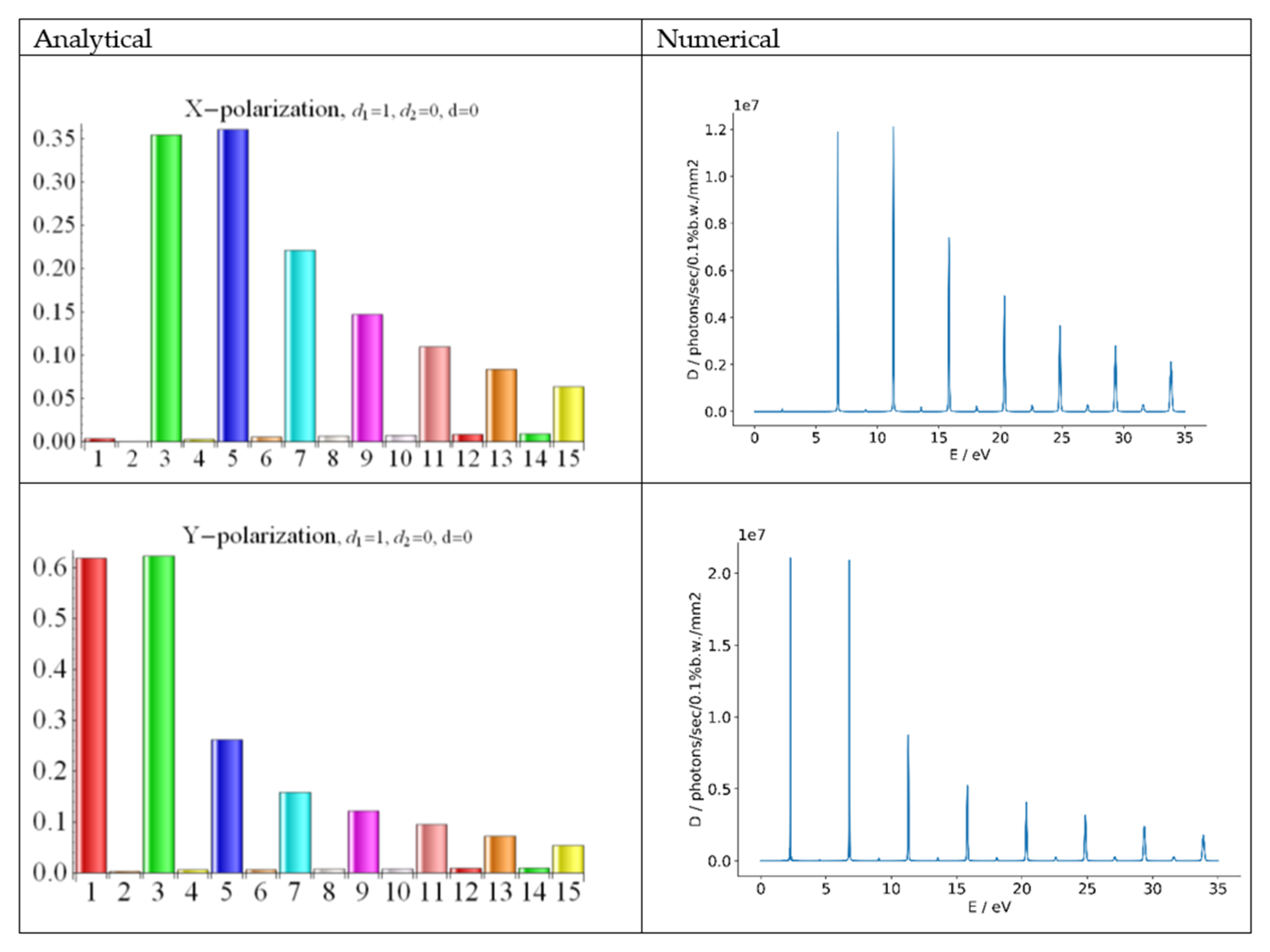
There was very good agreement between the analytical results, obtained straight from the fundamental concept of radiation and averaged over the electron energies of the beam, and the numerical results; for certainty, we assumed a beam energy E = 150 MeV and an undulator with the period λu = 2.8 cm and k = 2.133. It is worth remembering that the relative spectral distribution of UR is determined by the undulator and not by the beam, which is different from SR, where the electron energies determine the harmonic ratios and the overall spectrum shape. The small beam emittance (see Table 1) mainly affected the even harmonics. The third y-field harmonic in Equation (23) determined the x-polarization of the radiation in Figure 1; there, the fundamental frequency was absent, and the total and relative radiation powers for the third harmonic at the wavelength λ3 = 183 nm were thus increased. The Bessel factors are fy;n = 1,3,5 ≈ {0.81, 0.33, 0.15} and fx;n=1,3,5 ≈ {0.06, 0.25, 0.18}.
For h = 1 in Equation (22), we evidently got a kind of a planar undulator, viewed in an angle around the axis, so that its deflection parameter was . The UR resonances and other properties changed accordingly.
Consider the following undulator field with the phase-shifted sine–cosine configuration:
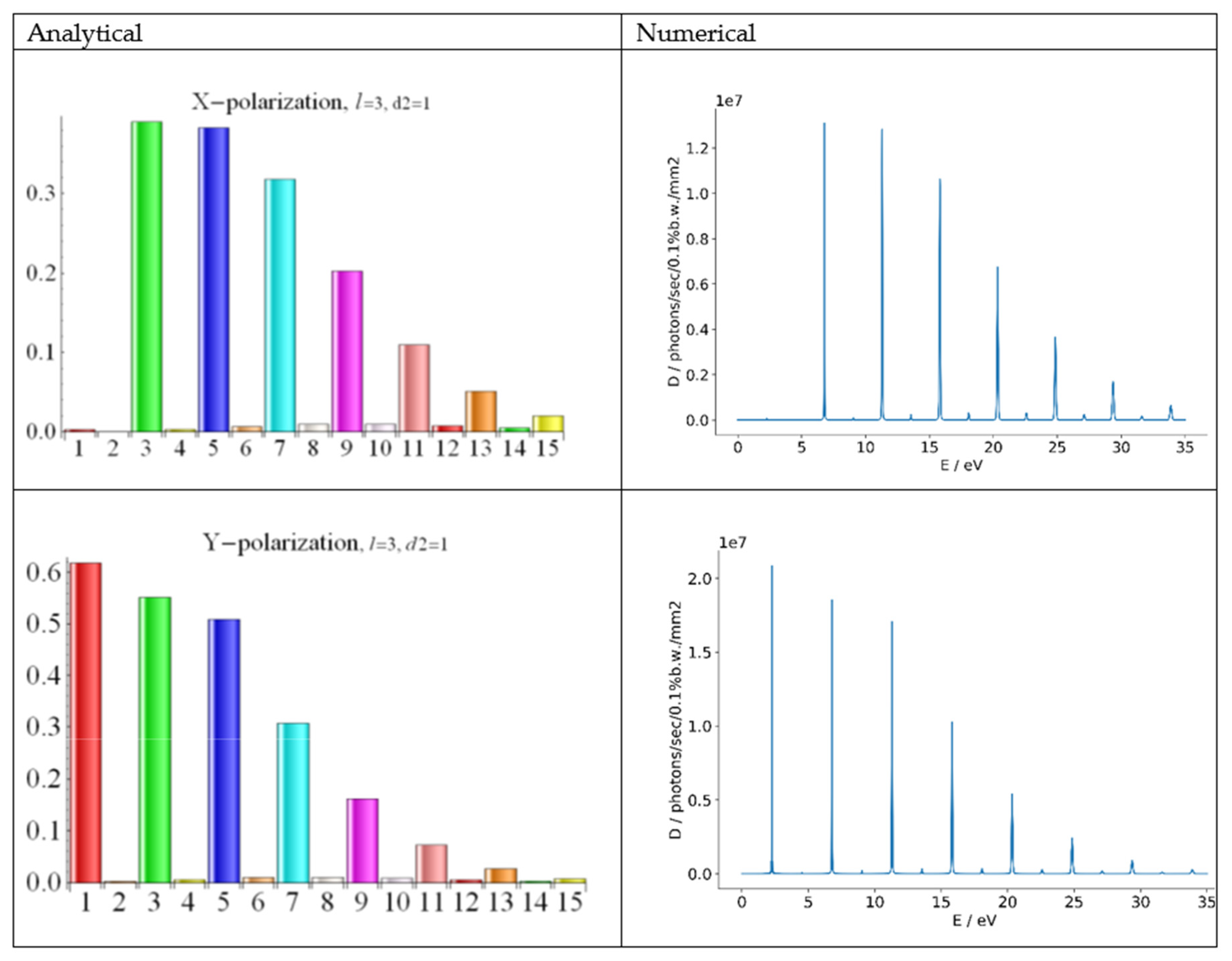
For the same electron beam, undulator strength, and period as reported in Table 1, we got the radiation spectrum shown in Figure 2. Note that higher harmonics with n = 5,7, …, were stronger than those from the field of Equation (23) in Figure 1.
The enhanced radiation of higher UR harmonic from the undulators with the fields of Equations (23) and (24) was due to the additional x-polarization, where the third and fifth harmonics dominated (see Figure 1 and Figure 2). However, one may wonder if it would be worth making an asymmetric elliptic undulator with the fields of Equations (23) and (24), with a short period along one coordinate and longer period along another coordinate. To answer this question, we considered a planar undulator with the same amplitude of the magnetic field H0 and the only period λu/3, in contrast with the bi-harmonic undulator with two periods λu and λu/3 in Equations (23) and (24). The considered undulator field read as follows:
An undulator with the magnetic field of Equation (25) had a three-times-smaller parameter k than the k of the undulators with the fields of Equation (23) and (24); the radiation wavelength (Equation (10)) was much shorter for the field of Equation (25) than for the fields of Equations (23) and (24). Here, we do not discuss a technical possibility to reduce the period by the factor of three for the same field strength; we assumed that the undulator with the short-period field of Equation (25) could be built, and a long-period undulator (fields of Equations (23) and (24)) could thus be built too. We compared the radiation from the undulator with field of Equation (25) with that with the fields of Equations (23) and (24) in Figure 1 and Figure 2 for the same beam (see Table 1). In this way, we checked whether the additional line of long-period magnets could enhance harmonic radiation compared with the field of Equation (25). Note that since the field strengths and the undulator periods were different in the fields of Equations (25), (23), and (24), we got different values of λn (Equation (10)), and the comparison could not be done at the same identical wavelengths. Moreover, the shape of the UR spectrum was determined by the effective deflection parameters k; since k was different for Equation (25) from that for Equations (23) and (24), we got different overall spectrum shapes. Thus, we could only estimate, for example, the radiation intensity for the seventh harmonic of the undulator with the field of Equation (24) and compare it with that of the fundamental frequency of the undulator with the field of Equations (25) for some given field amplitude and undulator length.
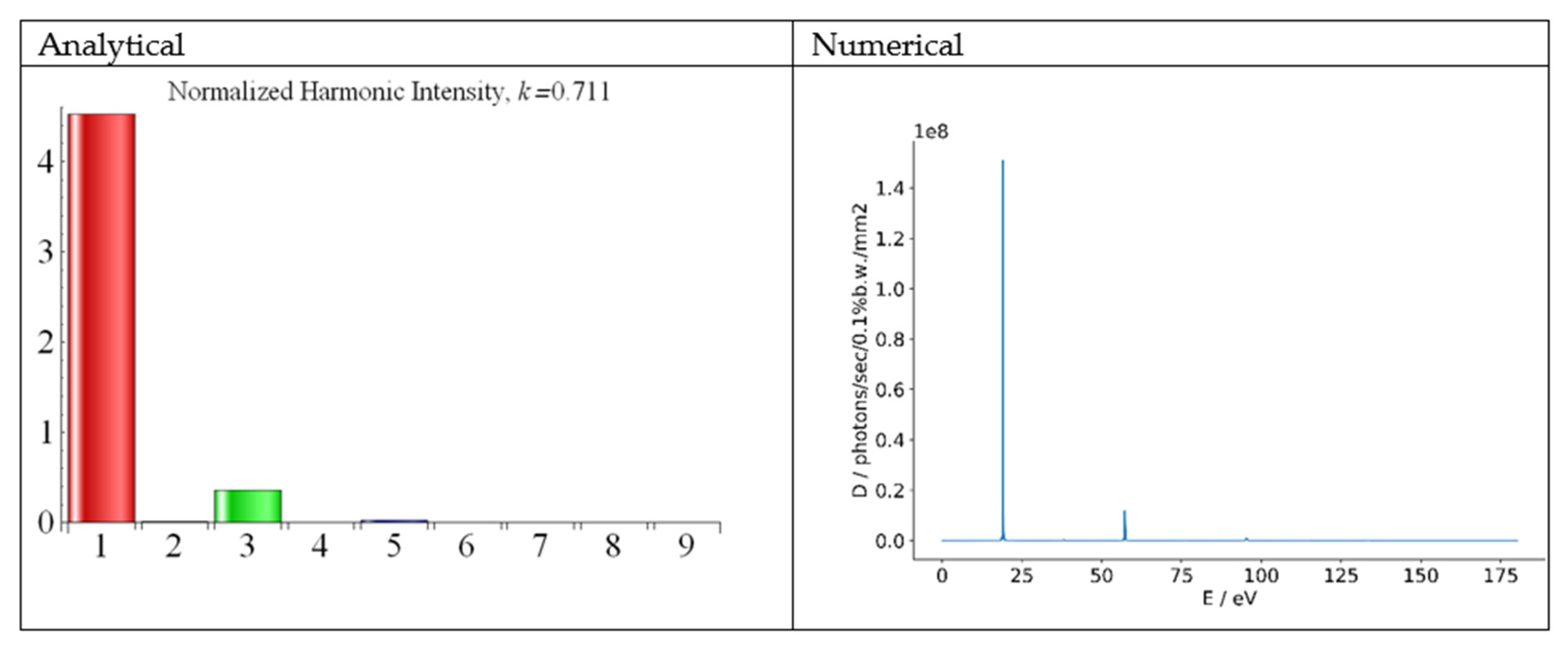
For certainty, we assumed the data in Table 1. The undulator field of Equation (25) had the period cm; the k parameter was . For the same total length L = 2.1 m (see Table 1), the undulator with the field of Equation (25) had 225 periods. For the electron energy E = 153 MeV (see Table 1), the fundamental wavelength in the magnetic field of Equation (24) was λ1 = 549 nm; the fundamental wavelength in the field of Equation (25) was λ1 = 65 nm. For a correct comparison, we accounted for the renormalization factor of Equation (12): , where k2 = 0.711 and k1 = 2.133. While accounting for the energy spread , (see Table 1), we computed and show in Figure 3 the spectrum of the UR in the field of Equation (25).
A comparison of the intensity of the fundamental tone λ1 ≈ 65 nm of the planar undulator of Equation (25) (see Figure 3) with that of the ninth harmonic λ9 ≈ 61 nm of the elliptic undulator of Equation (24) (see Figure 2) showed that the fundamental frequency of the planar undulator of Equation (25) was stronger than the ninth harmonic of the elliptic undulator of Equation (24). The difference was roughly one order of magnitude (compare the height of the red bar in Figure 3 with that of magenta bars in Figure 2); the ratio was higher for the harmonics, radiated in the pure sinusoidal symmetric field of Equation (23).
Our numerical and analytical results agreed with each other very well in all cases (see Figure 1, Figure 2 and Figure 3). The agreement was also very good for the even harmonics, as seen in Figure 1 and Figure 2. This confirmed the correctness of the account for the off-axis effects in our analytical model. The analytical results for the Bessel factors could be successfully used in the FEL analytical model.
Now, let us consider the FEL radiation; for a given electron energy and current density, the dimensionless Pierce parameter of Equation (8) depends on the value . For the seventh and ninth UR harmonics of the asymmetric elliptic undulator of Equation (24), we got , respectively, for λ7 = 78 nm and λ9 = 61 nm, while for the fundamental tone of the planar undulator of Equation (25) at λ = 65 nm, we got . These values were comparable with each other, and thus we conclude that the fundamental frequency of the planar undulator with the field of Equation (25) was amplified in an FEL approximately as well as the harmonics at close wavelengths of ~60–80 nm in the elliptic undulator with the field of Equation (24). We only considered the independent amplification of the harmonics and omitted the nonlinear term induced by the fundamental frequency of the elliptic undulator of Equation (24).
The following anti-symmetric third field harmonic was observed in a helical undulator [53]:
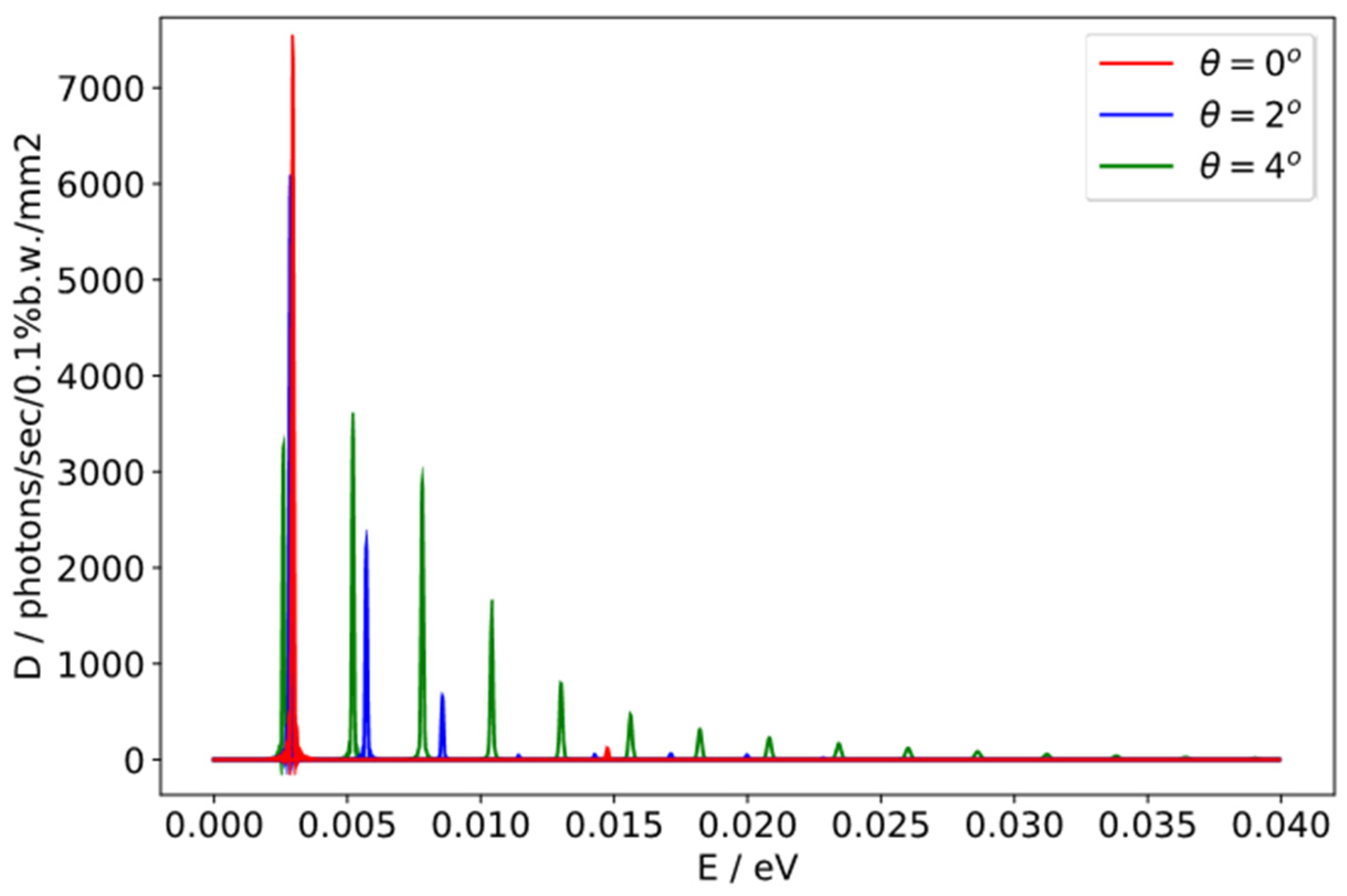
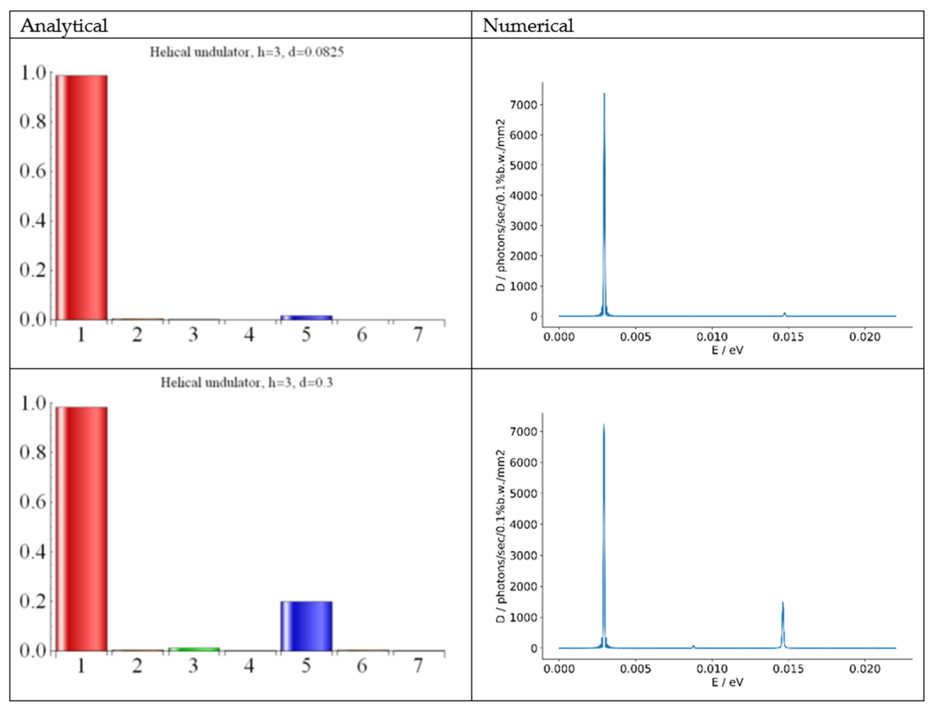
where h = 3, λu = 2.3 cm, and k = 2.216. The amplitude of the third field harmonic was small: d = 0.0825. An experiment KAERI [53] was conducted with low energy electrons with E = 6.5 MeV. The radiation wavelength of the fundamental tone was λ = 0.42 mm. The data of the accelerator and the light source are collected in Table 2. The harmonic intensities for the UR in the field of Equation (26) were reported in [53]; the fifth UR harmonic content on the undulator axis was ≈2% on the background of noise and second harmonic in the asymmetric wide beam. Our numerical calculations with the SPECTRA code had good agreement with the data in [53], especially for odd harmonics both on and off the axis (see Figure 4); we got some weaker even harmonics and a clearer picture with less noise and less split UR lines than in [53]; the analytical results looked similar and are omitted for conciseness.
In the angle 2° off the undulator axis, we saw very strong second and third harmonics with ~9% content (see blue line in Figure 4); the fifth harmonic, visible on the axis with 2% content (see red line in Figure 4), vanished in the angle 2° off the axis. In the angle 4° off the axis (see green line in Figure 4), the spectrum was wide and consisted of the first six strong harmonics, as well as higher harmonics.
The Bessel functions for the UR in the field of Equation (26) were reported in [61] (see also [21,54]). The spectrum of the UR in the helical field of Equation (26) with a field harmonic expectantly had dominant fundamental tone; its photon energy ≈0.003 eV corresponded the reported wavelength λ = 0.42 mm in [53]. Interestingly, the second strongest harmonic on the axis was the fifths; it was stronger than the third UR harmonic. We computed the harmonic radiation both analytically and numerically with SPECTRA; the results, shown in Figure 5, demonstrated nearly perfect agreement and confirmed the 2% content of the fifth harmonic radiation for d = 0.0825 in Equation (26). The strong third field harmonic in Equation (26) with the amplitude d = 0.3 yielded a higher content for the fifth UR harmonic: ≈20%; the third UR harmonic remained weak (see Figure 5). Note that due to multiple field components in the undulator field of Equation (26), the radiation wavelength of Equation (10) was much longer than that from a planar undulator with the same k and the same field harmonic along one coordinate. Moreover, the wavelength of the fifth UR harmonic, radiated in the undulator field of Equation (26), equaled that of the third UR harmonic, radiated in the planar magnetic field with only x- (or y-) components of Equation (26).
The evaluations for an FEL can be done based on the values of and the Pierce ρ parameter of Equation (8), which determines FEL performance. Assuming d = 0.3 in Equation (26), we got for the undulator field of Equation (26) and the FEL harmonics with n = 1 and n = 5: . The possible performance of an FEL with such helical undulator with the anti-symmetric third field harmonic of Equation (26) was explored analytically in [21,54] and numerically in [61]. For d = 0.3 in Equation (26), the power evolution of the fifth FEL harmonic mainly developed in the nonlinear regime induced by the fundamental frequency towards the end of the FEL; its saturated power was marginally above the initial shot noise. Thus, it was hard to exploit it. The behavior of the spontaneous and stimulated SASE FEL radiation in the case of even stronger third field harmonic with the amplitude d = 1 in Equation (26) was explored in [62]. The fifth and third harmonics of the SASE FEL had roughly equal saturated powers, ~0.1% of the fundamental frequency. However, for d = 1 in Equation (26), the terms did not help the harmonic radiation compared with that in the field , but they radically decreased the radiation frequency, thus annihilating any advantage that the third field harmonic could have given. Thus, the antisymmetric helical undulator field of Equation (26) was inadequate for FEL harmonic generation.
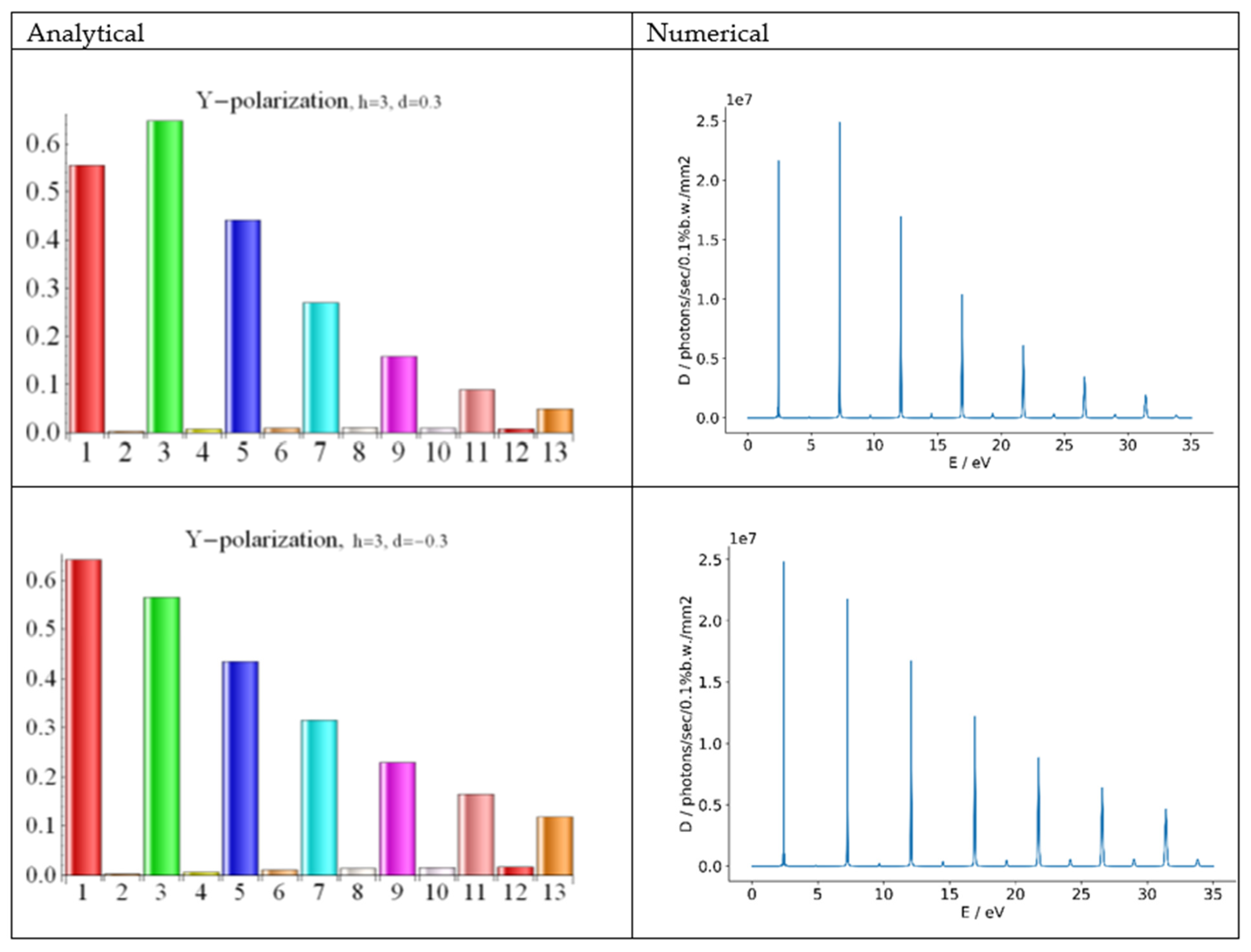
Let us now consider a planar undulator with the following symmetric third field harmonic:
The UR spectrum can be regulated to some extent by the third field harmonic [44,45]. We assumed a reasonably strong third field harmonic, h = 3, with an amplitude ±0.3H0 in Equation (27) and other parameters of the undulator and the beam from Table 1. Then, dependently on the field harmonic phase, h = ±3, we got the results shown in Figure 6. Note that for d = +0.3, the third UR harmonic was enhanced, and for d = −0.3, it was weakened compared with the radiation from a common planar undulator, where d = 0. Evidently, d = +0.3 in Equation (27) enhanced the radiation of the third UR harmonic; the latter had y-polarization. A comparison of the spectrum of the planar undulator with the field of Equation (27) with the spectrum of the elliptic undulator with the field of Equation (26) showed that the third UR harmonic in Equation (27) had approximately the same wavelength as the fifth UR harmonic in Equation (26). However, the third UR harmonic, emitted in the planar field of Equation (27) (see green bars in Figure 6) was much stronger than the fifth UR harmonic emitted in the elliptic field of Equation (26) (see blue bar in Figure 5) for the same amplitude d of the field harmonic.
For the FEL radiation from electrons in the planar field of Equation (27), we computed the FEL parameter of Equation (8) for d = 0.3 and got for the harmonics n = 1 and n = 3, respectively. Note that in the field of Equation (27), we got for the third UR harmonic twice the value of κ as that for the fifth UR harmonic in the field of Equation (26): ≈ 2 × ; this was for the same radiation wavelength and field amplitude d = 0.3. This strongly showed the advantages of the symmetric planar field of Equation (27) vs. the field of Equation (26).
Thus, the simpler planar undulator with the field of Equation (27) is preferable to the elliptic undulator with the field of Equation (26), which is more complicated and does not give a high enough harmonic intensity. Further discussion of the effect of sign of d and k in Equation (27) on the Bessel factors fn can be found, for example, in [28,31,32,34,40].
5. Harmonic Radiation in Undulators with Variable k Parameter
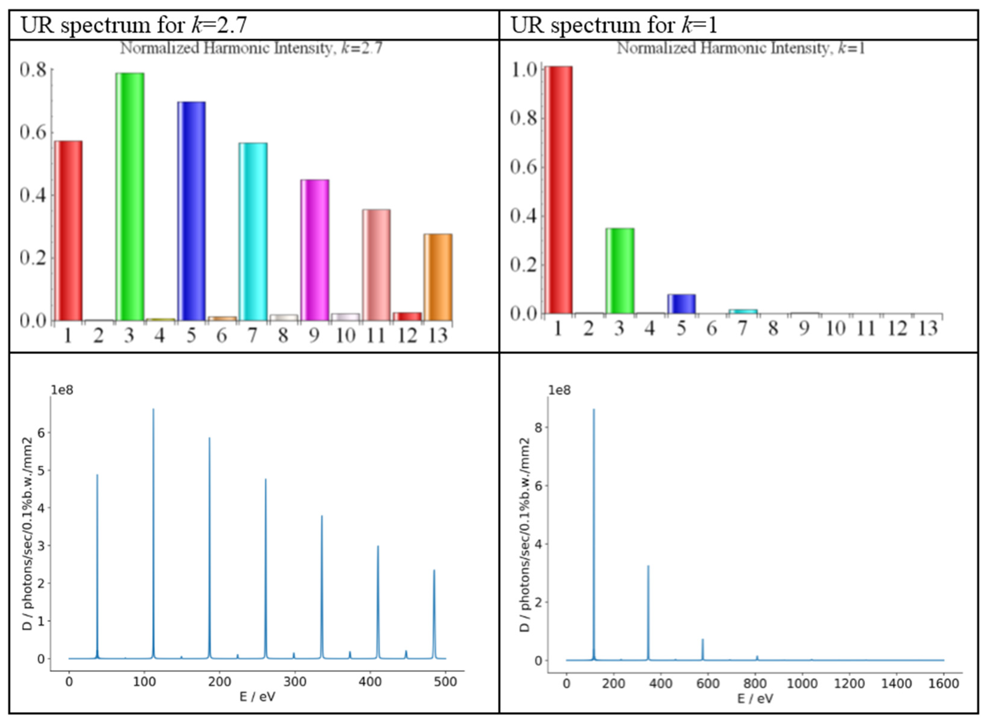
At some FEL facilities, undulators with variable deflection parameters are used, e.g., FLASH 2, European FEL, SACLA FEL, and SwissFEL. At the FLASH 2 facility [63,64], the electron energies are in the range of E = 0.45–1.2 GeV, the absolute energy spread is 0.5 MeV, the electron current is I0 < 2.5 kA, the emittances are εx,y = 1.4 μm × rad, and the Twiss parameters are βx,y = 6 m. The undulator period is λu = 3.14 cm, the deflection parameter k varies in the range of , and each undulator section is 2.5 m long. The radiated FEL wavelengths are in the range of nm. A variable k parameter allows for the use of undulators for the SASE FEL and for harmonic self-seed (HHSS) in the high gain harmonic generation (HGHG) FEL, where the last undulator sections are tuned to the high harmonic of the first sections. The range of variation of k allows for the amplification of the third harmonic of the first sections in the last sections. Consider one of the FEL experiments at FLASH 2 [63] with a beam current I0 = 600 A, an electron energy E = 757 MeV, an energy spread σe = 0.66×10⁻³, an undulator parameter for the first sections k = 2.687, and an undulator parameter for the last sections k = 1.032; the fundamental wavelength from the buncher was λ = 33 nm. The undulator cascades of the amplifier with k = 1.032 were tuned to the third harmonic λ3 = 11 nm of the first sections. We computed the spontaneous and the stimulated UR for it.
The spontaneous UR spectra from the first and last undulator sections are shown in Figure 7. It follows from Figure 7 that the third UR harmonic of the undulator with k = 2.7 (green bar in the left plot) was weaker than the fundamental tone of the undulator with k = 1 (red bar in the right plot). Thus, for the spontaneous UR at λ = 11 nm, it may be favorable to use the fundamental frequency of the undulator with k = 1.0.
Now let us evaluate the FEL radiation from FLASH 2 undulators. For the fundamental wavelength λ = 33 nm of the buncher, whose undulators had k = 2.7, we got: → 0.162 and a Pierce parameter . For the third FEL harmonic λ3 = 11 nm of the buncher for k = 2.7, the Pierce parameter was practically the same as that for the fundamental frequency at the same wavelength λ = 11 nm of the amplifier, where k = 1: 0.093 and . Thus, the independent amplification of the third FEL harmonic of the undulator with k = 2.7 was the same as the amplification of the fundamental frequency of the undulator with k = 1; this was different from the spontaneous UR results in Figure 7. In addition to the independent harmonic generation, there was a contribution induced by the fundamental tone on the third harmonic wavelength that helped to amplify the third harmonic at 11 nm in the undulator with k = 2.7, and the radiation power at 11 nm grew faster towards the end of the buncher. However, the saturation of the fundamental frequency did not allow for the further growth of the third FEL harmonic; moreover, the fundamental tone induced the energy spread towards the end of the FEL. To avoid this negative effect, the buncher was cut far from saturation, where and amplification in the following cascades was ensured. The fact that the buncher was cut after the fourth section [63] meant that our theoretical estimations agreed with those of the engineers at FLASH 2.
The further amplification and radiation of the λ = 11 nm harmonic occurred in the amplifier, whose undulators had k = 1 and whose fundamental frequency resonated with the third harmonic of the buncher.
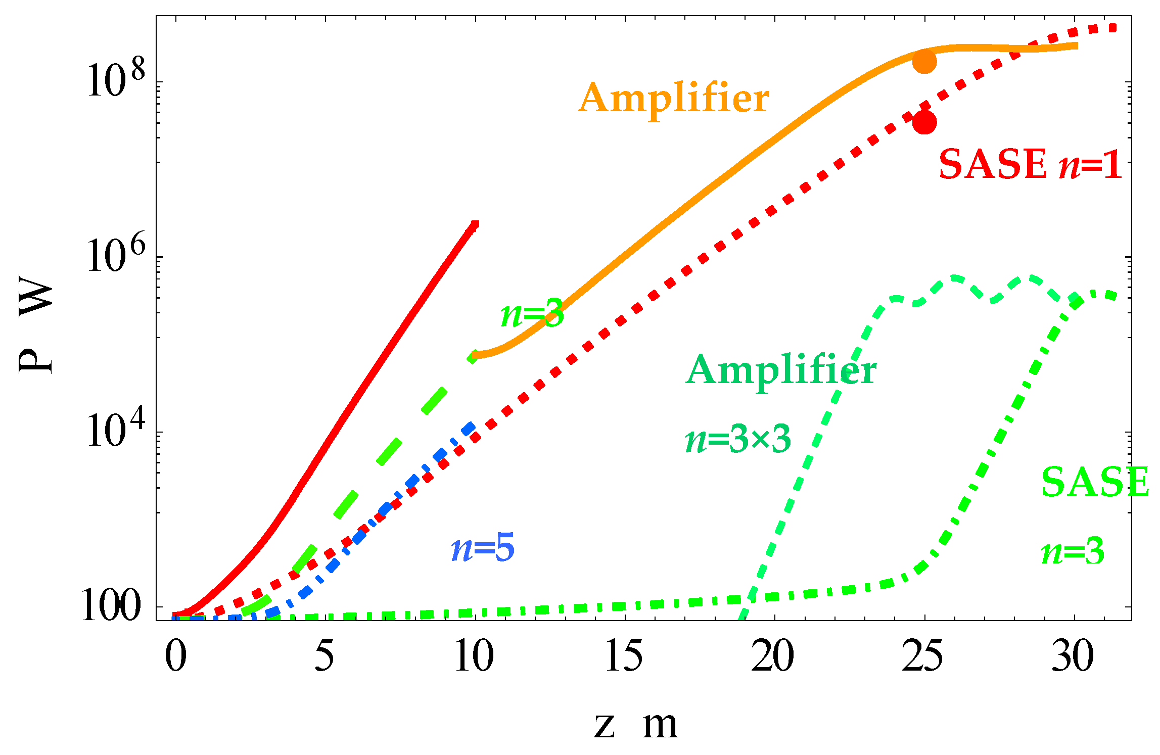
In Figure 8, we present the modeling of the harmonic power evolution in the FEL undulators of FLASH 2 in the above-described experiment for harmonic self-seeded HGHG and SASE FEL; in the latter case, all undulators were tuned to k = 1 and the fundamental wavelength of λ1 = 11 nm was radiated.
The modeling was done with the phenomenological FEL model [55,56,57,58,59], where the exact formulae from Section 3 for the Bessel factors, verified numerically, were used. The model is reliable and has given predictions close to the measured values for the harmonic power evolution in FEL experiments in wide range of parameters and radiated wavelengths [54,55,56,57,58,59,60]. The photon pulse energy, measured after 10th undulator section, was higher for HGHG than for SASE FEL (compare the orange and red dots that denote the respective powers). The results of our analysis (see Figure 8) confirmed that the amplification of the third harmonic in the buncher with k = 2.7 (see Figure 8 at 10 m) was better than that of the fundamental frequency in the SASE FEL at the same length; the proper harmonic gain length was also shorter for HGHG due to the induced contribution from the fundamental frequency. This advocated for buncher use in harmonic amplification and made the self-seeded HGHG FEL preferable to SASE at the same harmonic wavelength. The details of the experiment can be found in [64]. The reported photon pulse energies agreed well with our theoretical results (see colored orange dot and red dot in Figure 8 at 25 m of pure undulator length).
6. Results and Conclusions
In this work, we studied the spontaneous UR and SASE FEL radiation in undulators with field harmonics. We presented exact analytical expressions for the Bessel factors for the UR harmonics, emitted in multiperiodic magnetic fields. We compared all the analytical results with accurate numerical calculations, performed with the SPECTRA program. We considered examples of real undulators and beams in existing installations and accounted for the emittances, energy spread, focusing, etc. We also theoretically considered some undulators with strong field harmonics. The agreement between the analytical and numerical results was remarkably good for every studied undulator and electron beam setup. The results for the spontaneous UR harmonic generation in helical, elliptic, and planar undulators with field harmonics are the following:
- Elliptic undulators with field harmonics are not the best choice for harmonic generation. This includes undulators with both symmetric and asymmetric elliptic fields with third harmonics along with one and two coordinates. These undulators provide elliptic polarizations of the radiation, but their UR harmonic content is inferior to that of a planar undulator with the same harmonic in the magnetic field. Moreover, because of the main field harmonic is present alongside both coordinates in helical undulators, their spectrum is lower than that of a planar UR.
- A helical undulator with an antisymmetric third field harmonic has a noticeable fifth UR harmonic and a very weak third harmonic in the spectrum. However, this fifth UR harmonic is not enough strong for practical use. In an FEL, it is mainly induced by the fundamental frequency and barely reaches 0.01–0.1% of content. A planar undulator with the same magnetic field along one axis radiates the third UR harmonic at the wavelength, similar to that of the fifth UR of a helical undulator. However, the third harmonic of the planar undulator is much stronger than the fifth of the helical with field harmonics.
- The third UR harmonic of a planar undulator with kτ 1.5 can be enhanced by the third field harmonic if the latter comes in phase with the main undulator field.
We applied our results to FEL radiation and estimated the values of the Pierce parameter for the considered undulators. The following results are worth mentioning:
- For a fixed radiation wavelength, electron energy, and beam current, the Pierce parameter ρ for the fundamental frequency of an FEL with a planar undulator with kδ 1 was nearly the same as the values of ρ, as computed for the harmonics of an elliptic undulator with the matching wavelengths and kτ 2.5.
- In an FEL amplifier, there seemed to be little difference when using the fundamental frequency of a common planar undulator with low k, a third harmonic of a planar undulator with higher k, or a fifth or higher UR harmonic with a similar wavelength radiated in an elliptic undulator. The latter is more complicated and has higher costs.
- For the harmonic radiation, we advocate a planar undulator with symmetric third field harmonic; it gives a larger Pierce parameter for its UR harmonics compared to that of elliptic undulators at the same radiation lengths of matching harmonics.
Moreover, we considered spontaneous and FEL radiation in undulators with a variable k parameter. In particular, we studied radiation from undulators of FLASH 2 FEL, Germany. We computed the spectrum and harmonic intensities for the highest possible undulator parameter k = 2.7 at FLASH 2 and compared it with that for k = 1. Our analytical and numerical results were in agreement and demonstrated the following:
- At FLASH 2, the third UR harmonic of the undulator with k = 2.7 resonated with the fundamental tone of the undulator with k = 1.
- Due to the enhanced harmonic radiation from the undulator with k = 2.7, it is best for a buncher in an FEL with harmonic multiplication cascades. For k = 1, the fundamental tone dominated, and k = 1 could be used in the amplifying cascades.
In the experiment at FLASH 2 with the beam energy E = 757 MeV, λ = 11 nm radiation was generated. The first four undulators with k = 2.7 grouped electrons at the wavelength of the third harmonic, λ3 = 11 nm of the fundamental wavelength of λbuncher = 33 nm. Further amplification occurred in the undulators with k = 1 for the fundamental tone, resonating with the third harmonic of the buncher.
- The energy spread at the end of the buncher after the fourth cascade was lower than the Pierce parameter values: .
- The bunching at the third harmonic wavelength in the undulators with k = 2.7 was more efficient than that at the fundamental wavelength in the undulators with k = 1. This was due to the induced bunching from the fundamental frequency to the third harmonic of the buncher.
- The radiation pulse energy of the fundamental wavelength λ = 11 nm of the SASE FEL, where all undulators had k = 1, was lower along the FEL compared with the radiation energy of the harmonic self-seeded FEL, where the buncher sections with k = 2.7 grouped electrons at the harmonic wavelength λ3 = 11 nm.
- The power of the fundamental frequency in SASE regime rose later than the power of the harmonic from the buncher in the harmonic multiplication regime (HGHG, HHSS, or other). This is a general conclusion that applies to any installation with undulators with a variable k parameter.
- Our theoretical results for the harmonic radiation at FLASH 2 agreed with the reported values of the photon pulse energies.
The proposed analysis can be easily done for any undulator and FEL with other parameters.
Author Contributions
Data curation, I.F., K.Z.; Formal analysis, K.Z.; Investigation, K.Z.; Software, I.F.; Visualization, I.F.; Writing—original draft, K.Z. Both authors have read and agreed to the published version of the manuscript.
Funding
This research received no external funding.
Acknowledgments
The authors are grateful to A. Borisov, A. Vasiliev and principle researcher A. Lobanov for fruitful discussions of the mathematical and physical aspects of the SR and UR.
Conflicts of Interest
The authors declare no conflict of interest.
References
- Artcimovich, A.L.; Pomeranchuk, I.J. Radiation from fast electrons in a magnetic field. J. Phys. USSR 1945, 9, 267. [Google Scholar]
- Ginzburg, V.L. On the radiation of microradiowaves and their absorbtion in the air. Isvestia Akademii Nauk SSSR 1947, 2, 1651. [Google Scholar]
- Motz, H.; Thon, W.; Whitehurst, N.J. Experiments on radiation by fast electron beams. Appl. Phys. 1953, 24, 826. [Google Scholar] [CrossRef]
- Motz, H. Applications of the radiation from fast electron beams. J. Appl. Phys. 1951, 22, 527. [Google Scholar] [CrossRef]
- Madey, J.M.J. Stimulated Emission of Bremsstrahlung in a Periodic Magnetic Field. J. Appl. Phys. 1971, 42, 1906–1913. [Google Scholar] [CrossRef]
- Becker, W. Increasing the frequency of a free electron laser by means of a linearly polarized magnetic field. Eur. Phys. J. B 1981, 42, 87–94. [Google Scholar] [CrossRef]
- Colson, W.B. Free-electron lasers operating in higher harmonics. Phys. Rev. A 1981, 24, 639–641. [Google Scholar] [CrossRef]
- Alferov, D.F.; Bashmakov, Y.A.; Bessonov, E.G. Undulator radiation. Sov. Phys. Tech. Phys. 1974, 18, 1336. [Google Scholar]
- Alferov, D.F.; Bashmakov, Y.; Cherenkov, P. Radiation from relativistic electrons in a magnetic undulator. Sov. Phys. Uspekhi 1989, 32, 200–227. [Google Scholar] [CrossRef]
- Bagrov, V.G.; Bisnovaty-Kogan, G.S.; Bordovitsyn, V.A.; Borisov, A.V.; Dorofeev, O.F.; Ya, V.; Pivovarov, Y.L.; Shorokhov, O.V.; Zhukovsky, V.C. Synchrotron Radiation Theory and Its Development; Bordovitsyn, V.A., Ed.; Word Scientific: Singapore, 1999; p. 447. [Google Scholar]
- Vinokurov, N.A.; Levichev, E.B. Undulators and wigglers for the production of radiation and other applications. Phys.-Uspekhi 2015, 58, 850–871. [Google Scholar] [CrossRef]
- McNeil, B.W.J.; Thompson, N.R. X-ray free-electron lasers. Nat. Photonics 2010, 4, 814–821. [Google Scholar] [CrossRef]
- Pellegrini, C.; Marinelli, A.; Reiche, S. The physics of X-ray free-electron lasers. Rev. Mod. Phys. 2016, 88, 015006. [Google Scholar] [CrossRef]
- Huang, Z.; Kim, K.-J. Review of x-ray free-electron laser theory. Phys. Rev. Spéc. Top. Accel. Beams 2007, 10, 034801. [Google Scholar] [CrossRef]
- Saldin, E.L.; Schneidmiller, E.A.; Yurkov, M.V. The Physics of Free Electron Lasers; Springer Science and Business Media LLC.: Berlin/Heidelberg, Germany, 2000; Volume X, p. 470. Available online: https://www.springer.com/gp/book/9783540662662 (accessed on 13 January 2021).
- Bonifacio, R.; Pellegrini, C.; Narducci, L. Collective instabilities and high-gain regime in a free electron laser. Opt. Commun. 1984, 50, 373–378. [Google Scholar] [CrossRef] [Green Version]
- Schmüser, P.; Dohlus, M.; Rossbach, J.; Behrens, C. Free-Electron Lasers in the Ultraviolet and X-ray Regime; Springer Science and Business Media LLC.: Hamburg, Germany, 2014; Volume XV, p. 231. Available online: https://www.springer.com/gp/book/9783319040806 (accessed on 13 January 2021).
- Pellegrini, C. X-ray free-electron lasers: From dreams to reality. Phys. Scr. 2016, 2016, 014004. [Google Scholar] [CrossRef]
- Margaritondo, G.; Ribic, P.R. A simplified description of X-ray free-electron lasers. J. Synchrotron Radiat. 2011, 18, 101–108. [Google Scholar] [CrossRef] [Green Version]
- Margaritondo, G. Synchrotron light: A success story over six decades. Riv. Nuovo Cim. 2017, 9, 411–471. [Google Scholar]
- Zhukovsky, K.V. Analysis of harmonic generation in planar and elliptic bi-harmonic undulators and FELs. Results Phys. 2019, 13, 102248. [Google Scholar] [CrossRef]
- Zhukovsky, K.; Kalitenko, A. Phenomenological and numerical analysis of power evolution and bunching in single-pass X-ray FELs. J. Synchrotron Radiat. 2019, 26, 159–169. [Google Scholar] [CrossRef]
- Zhukovsky, K.; Kalitenko, A. Phenomenological and numerical analysis of power evolution and bunching in single-pass X-ray FELs, addenda and errata. J. Synchrotron Radiat. 2019, 26, 605–606. [Google Scholar] [CrossRef] [Green Version]
- Zhukovsky, K. Two-frequency undulator in a short SASE FEL for angstrom wavelengths. J. Opt. 2018, 20, 095003. [Google Scholar] [CrossRef]
- Zhukovsky, K.; Kalitenko, A. Analysis of harmonic generation in planar undulators in single-pass free electron lasers. Russ. Phys. J. 2019, 62, 153–160. [Google Scholar] [CrossRef]
- Zhukovsky, K. High-harmonic X-ray undulator radiation for nanoscale-wavelength free-electron lasers. J. Phys. D 2017, 50, 505601. [Google Scholar] [CrossRef]
- Zhukovsky, K. Soft X-ray generation in cascade SASE FEL with two-frequency undulator. EPL 2017, 119, 34002. [Google Scholar] [CrossRef]
- Dattoli, G.; Mikhailin, V.V.; Ottaviani, P.L.; Zhukovsky, K.V. Two-frequency undulator and harmonic generation by an ultrarelativistic electron. J. Appl. Phys. 2006, 100, 084507. [Google Scholar] [CrossRef]
- Dattoli, G.; Doria, A.; Giannessi, L.; Ottaviani, P. Bunching and exotic undulator configurations in SASE FELs. Nucl. Instrum. Methods Phys. Res. Sect. A 2003, 507, 388–391. [Google Scholar] [CrossRef]
- Zhukovsky, K.V. Harmonic Radiation in a Double-Frequency Undulator with Account for Broadening. Mosc. Univ. Phys. Bull. 2015, 70, 232. [Google Scholar] [CrossRef]
- Zhukovsky, K. Emission and tuning of harmonics in a planar two-frequency undulator with account for broadening. Laser Part. Beams 2016, 34, 447–456. [Google Scholar] [CrossRef] [Green Version]
- Hussain, J.; Mishra, G. Spectral properties of two frequency harmonic undulator radiations and effect of energy spread. Nucl. Instrum. A 2011, 656, 101–106. [Google Scholar]
- Mishra, G.; Sharma, A. Bi-period undulator radiation and small signal free electron laser gain. Nucl. Instrum. Methods Phys. Res. Sect. A 2020, 976, 164287. [Google Scholar] [CrossRef]
- Mishra, G.; Gehlot, M.; Hussain, J.K. Spectral properties of bi-harmonic undulator radiation. Nucl. Instrum. Methods Phys. Res. Sect. A 2009, 603, 495–503. [Google Scholar] [CrossRef]
- Zhukovsky, K. High harmonic generation in undulators for FEL. Phys. Res. Sect. B 2016, 369, 9. [Google Scholar] [CrossRef]
- Zhukovsky, K. Generation of coherent soft X-ray radiation in short FEL with harmonic multiplication cascades and two-frequency undulator. J. Appl. Phys. 2017, 122, 233103. [Google Scholar] [CrossRef]
- Zhukovsky, K.V. Generation of X-ray radiation in free electron lasers with two-frequency undulators. Russ. Phys. J. 2018, 60, 1630. [Google Scholar] [CrossRef]
- Zhukovsky, K. High harmonic generation in the undulators for free electron lasers. Opt. Commun. 2015, 353, 35–41. [Google Scholar] [CrossRef]
- Zhukovsky, K. Harmonic generation by ultrarelativistic electrons in a planar undulator and the emission-line broadening. J. Electromagn. Waves Appl. 2014, 29, 132–142. [Google Scholar] [CrossRef]
- Jia, Q. Effect of undulator harmonics field on free-electron laser harmonic generation. Phys. Rev. Spéc. Top. Accel. Beams 2011, 14, 060702. [Google Scholar] [CrossRef]
- Alekseev, V.I.; Bessonov, E.G. O спoсoбах генерирoвания циркулярнo пoляризoваннoгo электрoмагнитнoгo излучения на ускoрителях и накoпителях заряженных частиц. In Proceedings of the 6th All-Union Workshop on Use of Synchrotron Radiation SR-84 (IYaF SO AN SSSR), Novosibirsk, Russia, November 1984; p. 92. [Google Scholar]
- Kolomenskii, A.A.; Sinil’shchikova, I.V.; Bessonov, E.G.; Alekseev, V.I.; Alieva, E.V.; Belovintzev, K.A.; Serov, A.V.; Cherenkov, P.A.; Gaskevich, E.B.; Bukin, A.I.; et al. Ондулятoрнoе излучение, лазеры на свoбoдных электрoнах. Tr. FIAN 1993, 214, 193. Available online: http://proceedings.lebedev.ru/0214-1993/ (accessed on 13 January 2021).
- Bessonov, E.G. PhIAS Preprint No. 18. Phys. Inst. Acad. Sci. USSR 1982. Available online: https://inis.iaea.org/collection/NCLCollectionStore/_Public/18/067/18067187.pdf (accessed on 13 January 2021).
- Bessonov, E.G. General and some particular solutions of the inverse problem of the particle radiation theory in external fields. Nucl. Instrum. Methods A 1989, 282, 405. [Google Scholar] [CrossRef]
- Alexeev, V.I.; Bessonov, E.G. On some methods of generating circularly polarized hard undulator radiation. Nucl. Instrum. Methods A 1991, 308, 140. [Google Scholar]
- Tanaka, T.; Kitamura, H. SPECTRA: A synchrotron radiation calculation code. J. Synchrotron Rad. 2001, 8, 1221–1228. [Google Scholar] [CrossRef] [PubMed]
- Tanaka, T. Numerical methods for characterization of synchrotron radiation based on the Wigner function method. Phys. Rev. Spéc. Top. Accel. Beams 2014, 17, 060702. [Google Scholar] [CrossRef]
- Tanaka, T. Coherent mode decomposition using mixed Wigner functions of Hermite–Gaussian beams. Opt. Lett. 2017, 42, 1576–1579. [Google Scholar] [CrossRef]
- Tanaka, T. Universal representation of undulator phase errors. Phys. Rev. Accel. Beams 2018, 21, 110704. [Google Scholar] [CrossRef] [Green Version]
- Stoer, J.; Bulirsch, R. Introduction to Numerical Analysis; Springer: New York, NY, USA, 1991. [Google Scholar]
- Dattoli, G.; Renieri, A.; Torre, A. Lectures on the Free Electron Laser Theory and Related Topics; World Scientific: Singapore; NJ, USA; London, UK; Hong Kong, China, 1993. [Google Scholar]
- Prakash, B.; Huse, V.; Gehlot, M.; Mishra, G.; Mishra, S. Analysis of spectral properties of harmonic undulator radiation of anelectromagnet undulator. Optik 2016, 127, 1639–1643. [Google Scholar] [CrossRef]
- Lee, K.; Mun, J.; Park, S.H.; Jang, K.-H.; Jeong, Y.U.; Vinokurov, N.A. Numerical investigation of the radiation characteristics of a variable-period helical undulator. Nucl. Instrum. Methods Phys. Res. Sect. A 2015, 776, 27–33. [Google Scholar] [CrossRef]
- Zhukovsky, K.V. Effect of the 3rd undulator field harmonic on spontaneous and stimulated undulator radiation. J. Synchrotron Rad. 2019, 26, 1481. [Google Scholar] [CrossRef] [Green Version]
- Zhukovsky, K.V. Analytical account for the off-axis effects and undulator field harmonics in FELs. Opt. Laser Technol. 2020, 131, 106311. [Google Scholar] [CrossRef]
- Zhukovsky, K.V. Analysis of the Influence of Nonperiodic Magnetic Fields and Off-Axis Effects on the Radiation of X-Ray FEL and Other FELs. Mosc. Univ. Phys. Bull. 2020, 75, 285–294. [Google Scholar] [CrossRef]
- Zhukovsky, K. Comparative analysis of the theoretical and experimental spectral properties of X-FELs. Results Phys. 2020, 19, 103361. [Google Scholar] [CrossRef]
- Zhukovsky, K.V. Synchrotron Radiation in Periodic Magnetic Fields of FEL Undulators—Theoretical Analysis for Experiments. Symmetry 2020, 12, 1258. [Google Scholar] [CrossRef]
- Zhukovsky Konstantin, Theoretical spectral analysis of FEL radiation from multi-harmonic undulators. J. Synchrotron Rad. 2020, 27, 1648–1661. [CrossRef] [PubMed]
- Zhukovsky, K.V. Undulator and FEL radiation with analytical account for the field harmonics and off-axis effects. Physics-Uspekhi 2020. [Google Scholar] [CrossRef]
- Kalitenko, A.M.; Zhukovskii, K.V. Radiation from Elliptical Undulators with Magnetic Field Harmonics. J. Exp. Theor. Phys. 2020, 3, 327–337. [Google Scholar] [CrossRef]
- Zhukovsky, K.V. Generation of UR Harmonics in Undulators with Multiperiodic Fields. Russ. Phys. J. 2019, 62, 1043–1053. [Google Scholar] [CrossRef]
- Faatz, B.; Braune, M.; Hensler, O.; Honkavaara, K.; Kammering, R.; Kuhlmann, M.; Ploenjes, E.; Roensch-Schulenburg, J.; Schneidmiller, E.; Schreiber, S.; et al. The FLASH Facility: Advanced Options for FLASH2 and Future Perspectives. Appl. Sci. 2017, 7, 1114. [Google Scholar] [CrossRef]
- Schneidmiller, E.; Faatz, B.; Kuhlmann, M.; Rönsch-Schulenburg, J.; Schreiber, S.; Tischer, M.; Yurkov, M.V. First operation of a harmonic lasing self-seeded free electron laser. Phys. Rev. Accel. Beams 2017, 20, 020705. [Google Scholar] [CrossRef]
Figure 1.
The undulator radiation (UR) harmonic intensities for the undulator field of Equation (23); left bar charts—analytical results, where the harmonics are numbered and their intensities are dimensionless; right plots—numerical results of SPECTRA, where the harmonic photon energy and brightness are reported.

Figure 2.
The UR harmonic intensities for the undulator field of Equation (24); left bar charts—analytical results, where the harmonics are numbered and their intensities are dimensionless; right plots—numerical results of SPECTRA, where the harmonic photon energy and brightness are reported.
Figure 2.
The UR harmonic intensities for the undulator field of Equation (24); left bar charts—analytical results, where the harmonics are numbered and their intensities are dimensionless; right plots—numerical results of SPECTRA, where the harmonic photon energy and brightness are reported.

Figure 3.
The UR harmonic intensities for the field of Equation (25); left bar chart—analytical results, where the harmonics are numbered and their intensities are dimensionless; right plot—numerical results of SPECTRA, where the harmonic photon energy and brightness are reported.
Figure 3.
The UR harmonic intensities for the field of Equation (25); left bar chart—analytical results, where the harmonics are numbered and their intensities are dimensionless; right plot—numerical results of SPECTRA, where the harmonic photon energy and brightness are reported.

Figure 4.
Numerical results from SPECTRA for the UR harmonic brightness in KAERI FEL undulator [53] with the field of Equation (26), where d = 0.0825; on-axis—red line; 2° off the axis—blue line; and 4° off the axis—green line.
Figure 4.
Numerical results from SPECTRA for the UR harmonic brightness in KAERI FEL undulator [53] with the field of Equation (26), where d = 0.0825; on-axis—red line; 2° off the axis—blue line; and 4° off the axis—green line.

Figure 5.
The UR harmonic intensities for the field of Equation (26) for d = 0.0825 in top plots and d = 0.3 in the bottom plots; left bar charts—analytical results, where the harmonics are numbered and their intensities are dimensionless; right plots—numerical results of SPECTRA, where the harmonic radiation energy and brightness are reported.

Figure 6.
The UR harmonic intensities for the field of Equation (27), d = +0.3—upper plots; d = −0.3—lower plots; left bar charts—analytical results for dimensionless intensities of the harmonics n; right plots—numerical results of SPECTRA, where the harmonic radiation energy and brightness are reported.

Figure 7.
The UR harmonic intensities for the FLASH 2 undulator; left bar charts—for k = 2.7; right plots—for k = 1.04.
Figure 7.
The UR harmonic intensities for the FLASH 2 undulator; left bar charts—for k = 2.7; right plots—for k = 1.04.

Figure 8.
Harmonic power evolution along the undulators in the free electron laser (FEL) FLASH 2 with energy E = 757 MeV, spread σe = 0.5 MeV, current I0 = 600 A, and charge Q = 0.25 nC. HGHG FEL for the 3rd harmonic at λ1×3 = 11 nm. The harmonics are color-coded; prebuncher: λ1 = 33 nm—red solid line; λ3 = 11 nm—green long dashed line; λn=5 = 6.6 nm—blue dot dashed line; amplifier λn=1×3 = 11 nm—orange line; λn=3×3 = 3.7 nm—dashed green line; and self-amplified spontaneous emission (SASE) FEL n = 1 at λ1 = 11 nm—red dotted line. The power of λ = 11 nm radiation was computed from the pulse energy, measured at 25 m; it is shown by the colored dots: Eγ = 53 μJ for HGHG FEL—red dot, and Eγ = 11 μJ the for SASE FEL—orange dot.


Table 1.
Parameters of the undulator and the beam for the field of Equation (23).
| Accelerator | Light Source | ||||
|---|---|---|---|---|---|
| Variable | Value | Variable | Value | Variable | Value |
| 300 | 1 × 10⁻³ | , cm | 2.8 | ||
| E, MeV | 153.3 | , m | 2.2 | L, cm | 210 |
| , m×rad | 2.5 × 10⁻⁶ | , m | 2.2 | 75 | |
| , m×rad | 2.9 × 10⁻⁶ | 0 | 2.133 | ||
| , A | 7.97 | 0 | 2.133 | ||
| 0.711 | |||||
Note that in Table 1 and Table 2, the values of the deflection parameter are reported from SPECTRA code: k accounts only for the main field harmonic along x-coordinates; and account for the effective deflection along x- and y-coordinates, respectively; and . We used in SPECTRA proper values of , and , dependently on the considered undulator.
Table 2.
Parameters of the undulator and the beam for the field of Equation (26) of the helical undulator [53].
Table 2.
Parameters of the undulator and the beam for the field of Equation (26) of the helical undulator [53].
| Accelerator | Light Source | ||||
|---|---|---|---|---|---|
| Variable | Value | Variable | Value | Variable | Value |
| 12.72 | 1 × 10⁻³ | , cm | 2.3 | ||
| E, MeV | 6.5 | , m | 0.4366 | L, cm | 69 |
| , m×rad | 1.5 × 10⁻⁶ | , m | 0.2875 | 30 | |
| , m×rad | 0.3 × 10⁻⁶ | 2.223 | 2.21622 | ||
| , A | 15.95 | 1.053 | 2.21706 | ||
Publisher’s Note: MDPI stays neutral with regard to jurisdictional claims in published maps and institutional affiliations. |
© 2021 by the authors. Licensee MDPI, Basel, Switzerland. This article is an open access article distributed under the terms and conditions of the Creative Commons Attribution (CC BY) license (http://creativecommons.org/licenses/by/4.0/).
Share and Cite
MDPI and ACS Style
Zhukovsky, K.; Fedorov, I. Spontaneous and Stimulated Undulator Radiation in Symmetric and Asymmetric Multi-Periodic Magnetic Fields. Symmetry 2021, 13, 135. https://doi.org/10.3390/sym13010135
AMA Style
Zhukovsky K, Fedorov I. Spontaneous and Stimulated Undulator Radiation in Symmetric and Asymmetric Multi-Periodic Magnetic Fields. Symmetry. 2021; 13(1):135. https://doi.org/10.3390/sym13010135
Chicago/Turabian StyleZhukovsky, Konstantin, and Igor Fedorov. 2021. "Spontaneous and Stimulated Undulator Radiation in Symmetric and Asymmetric Multi-Periodic Magnetic Fields" Symmetry 13, no. 1: 135. https://doi.org/10.3390/sym13010135
Note that from the first issue of 2016, this journal uses article numbers instead of page numbers. See further details here.