Design and Implementation of Web-Based Virtual Mobile Robot Laboratory for Engineering Education


1
Information System Engineering, Faculty of Technology, Kocaeli University, Kocaeli 41001, Turkey
2
Department of Information Technologies, Kocaeli University, Kocaeli 41001, Turkey
3
Biomedical Engineering, Faculty of Technology, Kocaeli University, Kocaeli 41001, Turkey
*
Author to whom correspondence should be addressed.
Symmetry 2020, 12(6), 906; https://doi.org/10.3390/sym12060906
Submission received: 10 May 2020
/
Revised: 23 May 2020
/
Accepted: 27 May 2020
/
Published: 1 June 2020
Abstract
:A web-based virtual and remote laboratory environment is developed, realized and proposed for real time control and monitoring of a mobile robot in an indoor environment. In this laboratory, a real time and continuous video stream of indoor laboratory environment is viewed by wireless IP camera mounted to the ceiling. The localization of the robot is also implemented using this IP camera. In this environment, a virtual target and virtual obstacles are located anywhere on the video image taken by the user. The robot is guaranteed to arrive at the virtual target avoiding virtual obstacles using the shortest path. The video stream of the robot’s navigation is monitored through the web environment. The robot is controlled by a BeagleBoard-xM single board computer. The PC web server symmetrically communicates with the other web server on the BeagleBoard-xM, executing developed application software. Since genetic algorithms generate alternative solutions, it is utilized as a path planning algorithm. Parameters such as population size and maximum generation of genetic algorithms applied to get the shortest path for the robot are tuned via the web-based virtual laboratory environment. The robot is also controlled manually through the web environment. At the conclusion of the experiments, the results are monitored on the web-based virtual laboratory environment. A low-cost mobile robot virtual remote laboratory is designed and implemented for engineering education in this paper. Consequently, survey and some experimental works, of the usability and performance of the RRC-Lab (remote robot control-laboratory) system are confirmed by students.
1. Introduction
Web-based research laboratories are commonly used for distance research or education. One of the advantages of these laboratories is sharing the expensive equipment or experimental setups. The other advantage is to allow the users to do experiments requiring only a PC and internet connection. One of the web-based laboratory applications is remote control of the robots. Numerous academic studies on web-based mobile robot applications can be seen in literature.
Guimarães et al. [1] suggest a virtual laboratory named REAL providing remote access to a mobile robot infrastructure. A sophisticated access framework, a communication infrastructure supporting multimedia flows, and a component-based software construction are employed in REAL. Open standards such as HTTP, HTML, XML, Java, et cetera, and a common object request broker architecture (CORBA) are benefits of REAL. They enable the researchers to do experiments on robot control and navigation methods [1]. Šafaric et al. [2] propose a remote rapid control prototyping (RRCP) based on MATLAB/Simulink, xPC target, and a custom developed embedded target for a DSP-2 controller and LabVIEW virtual instrument for both control and robotics engineering education [2]. Wei et al. [3] propose an internet based tele-control system for a mobile robot using a real time embedded controller design utilizing LabVIEW, a CCD camera and wireless internet connection [3]. Dinulescu et al. [4] propose a web-based remote laboratory for different navigation algorithms. A differential-drive PC-Bot 914 equipped with 5 IR sensors, a video camera, encoders and a wireless ethernet card is used as a mobile robot. A video network camera and the Microsoft Visual Studio development environment installed on the robot’s on-board computer are beneficial [4]. Popescu et al. [5] suggest a telematic system composed of a mobile robot having three IR sensors, sonar and encoders, a tablet PC for controlling and monitoring, a network video camera and a wireless network video camera. The system is used for the mobile robot experiments, including motor control, obstacle avoidance, image processing and application to trajectory control [5]. In Mester’s paper [6], the wireless sensor-based remote control of mobile robots in an unknown environment with obstacles using the Bluetooth wireless transmission and Sun SPOT technology is presented [6]. Sagiroglu et al. [7] prepare a web-based real time mobile robot platform named as Web-SUN providing monitoring, tele-controlling and programming for real time experiments employing only computer vision techniques. Web-SUN is composed of a three-wheel mobile robot system, a two-degrees-of-freedom camera motion unit, a portable PC, various controllers and wireless communication modules. They developed this platform using a camera and optical tachometers [7]. A remote laboratory based on MATLAB and Easy Java Simulations (EJS) for mobile robot applications is proposed by Neamtu et al. [8]. Casini et al. [9] designed a remote laboratory for multi robot experiments in an environment with virtual obstacles using LEGOMindstorms technology and a MATLAB environment [9]. Liu et al. [10] developed a common wireless remote control arrangement including multi-robot board control centers (PCs), a remote server control center (PC), a wireless communication network and an infrared radio navigation module with ceiling passive landmarks in 2012. They realized two experiments on finding the shortest path utilizing a hybrid Dijkstra–Floyd algorithm [10]. Aroca et al. [11] propose a web-based system using a smart phone as a main control computer of the robot. The architecture depends on Android, a Linux based operating system requiring little programming energy while executing the sophisticated tasks. The system enables the users to save, load and execute programs stored in the robot’s memory utilizing the web control panel. It also allows different programming languages, Python, Perl, Ruby, Lua, BeanShell, JavaScript, Tcl and Shell scripts, to be employed [11]. Santos et al. [12] propose an adaptive self-triggered control of a remotely operated P3-DX mobile robot providing greatly reduced wireless network traffic, while a significant reduction of the tracking performance was not achieved [12]. Antony et al. [13] propose web-based control and monitoring of telepresence robot in their TechRobot design consisting of Saber tooth or L293D motor drive, Arduino, ultrasonic sensor, Raspberry Pi, DC motor, 12 V battery, AFMLE, Wamp server, RS232 interface, WLAN devices, iPod or LCD display monitor, python.exe, and pyserial 2.7.exe. Ultrasonic sensor based obstacle detection and avoidance are realized [13].
Inanc and Dinh developed a low-cost autonomous mobile robot experimental setup including cameras and sonar sensors located on the robot for the use of students [14]. Stefanovic et al. propose a distance learning laboratory for control engineering students doing remote experiments [15]. Gill et al. suggest a robotic toolbox for students’ remote robot simulations [16]. Jara et al. developed a Java based virtual laboratory environment for students doing experiments on robots [17]. Berengule et al. propose a remote virtual laboratory for teaching computer and engineering students the fundamentals and methods of robotics [18]. Rampazzo et al. developed a remote refrigeration laboratory for control engineering education [19]. A remote laboratory called WebLab-Deusto has been proposed for students to use software and hardware by accessing real equipment at the university remotely. WebLab-Deusto is a project by Deusto University that aims to improve the quality of learning through the use and development of remote laboratories [20]. In order to develop and spread the use of innovative learning technologies in STEM education, the Go-Lab project that supports the use of online laboratories has been developed. The Go-Lab project is a free remote laboratory platform that can be used by any lecturer from any country. It is designed to meet educational needs for institutes, schools and lecturers worldwide [21].
As seen in literature reviews, various studies using different sensors, including IR sensors, ultrasonic sensors, sonars and encoders are performed. Some studies employ different expensive package programs like MATLAB and LabVIEW while some utilize a PC, laptop, smart phone or Raspberry Pi to control the mobile robots for different web-based experiments such as path planning, obstacle avoidance, object detection or object tracking. In most of the studies except [7] and [13], cameras are employed to monitor the robot’s navigation. In [13], ultrasonic sensor-based object detection and avoidance experiments are realized while the camera is used for face detection, object detection and object tracking benefitting OpenCV. In [7], no sensors except camera and optical tachometers are used while designing Web-SUN enabled real-time robot vision, control and programming exercises.
In this study, the RRC-Lab has a modular structure, including two modules namely RRC-Lab web interface module and mobile robot control module. The RRC-Lab web interface module supplies the communication between the user and the robot through the internet. The robot’s motion control is provided by the mobile robot control module. In this design system, only a wireless IP camera mounted to the ceiling of the laboratory is used for both real time monitoring of the indoor experimental environment and applying vision based obstacle avoidance experiments. The RRC-Lab is composed of a wireless IP camera, a PC network server, a wireless modem, a BeagleBoard-xM and a Pioneer P3-DX. The software components are PHP scripting language for web interfaces, jQuery framework for improving the interaction between the user and the web platform, Apache web server, PostgreSQL database server for storing the registration information of the users, the LightHTTPd web server installed on the BeagleBoard-xM for providing the web-based communication with the BeagleBoard-xM, OpenCV library for the image processing of the photo taken by the wireless IP camera, C programming language, genetic algorithm (GA) for determining the shortest path from the starting point to the target.
The RRC-Lab proposes an architecture, including both open source software having no cost and no license problems and low-cost hardware components as BeagleBoard-xM. In addition, the system architecture is built as a modular structure containing the RRC-Lab web interface module and the mobile robot control module making the system flexible so that the currently employed hardware, software and devices can be replaced with different ones. Furthermore, no other sensor is employed except a wireless IP camera, while similar studies are utilizing different sensors and cameras for this kind of study. Only an image of the laboratory environment taken from the wireless IP camera is processed for the robot to find the shortest path from the starting point to the target avoiding obstacles. Both the target and the obstacles are virtually placed by the user on the online video stream using the web interface. The real robot and virtual obstacles and target are used together, combining the real world with the virtual one on the same platform allowing the users to do experiments requiring only a PC having an internet connection. All these advantages combined in the same work make this study different and advantageous from other similar ones.
The user can do obstacle avoidance experiments by placing virtual obstacles and a target on the online video stream using the web interface. The user can also control the robot’s movements manually using a manual control web interface. The experimental results are viewed on the screen of the user’s web interface. Furthermore, the localization of the robot is also realized. The smallest rotation angle of the robot is determined so that the robot consumes the least energy while turning in any direction. This is another contribution of this study.
Furthermore, a survey was applied to Kocaeli University engineering students to evaluate the usability and performance of RRC-Lab. The survey results show that the RRC-Lab system provides students a way to learn mobile robot obstacle avoidance problems and genetic algorithms quickly, effectively and efficiently.
2. Proposed Method
A virtual control laboratory is designed for remote and real time motion planning and monitoring of the robot in an indoor environment. Real time obstacle avoidance experiments can be performed using virtual targets and obstacles. The system is accessed via the http://cbslab.kocaeli.edu.tr internet destination. However, this virtual laboratory is closed to external internet access, because it is not possible to reserve the laboratory environment just for our study. The experimental setup given in Figure 1 includes a wireless IP camera, a PC network server, a wireless modem, a BeagleBoard-xM and a Pioneer P3-DX. The BeagleBoard-xM is located on top of the Pioneer P3-DX. The RRC-Lab is a web-based, real time and wireless mobile robot control platform.
This platform uses Apache web server to broadcast to internet environment and offers a web-based wireless communication with the other components. Dynamic web pages of the platform are developed using the PHP web programming language. The user interaction with the web platform is advanced by using the jQuery framework and Ajax technique. The data are stored on the PostgreSQL database management system. The LightHTTPd web server runs on the BeagleBoard-xM to respond to the user’s HTTP requests. The developed robot control program is prepared using the OpenCV library with the C programming language. GA is used for generating the shortest path for the robot.
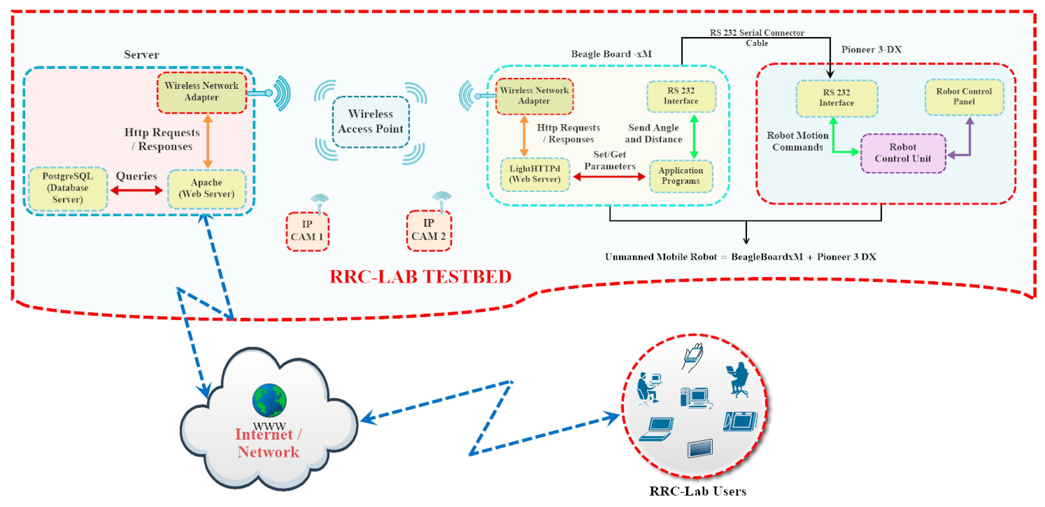
The developed platform includes two modular structures namely RRC-Lab web interface and mobile robot control module as seen in Figure 2. The RRC-Lab web interface module is designed for the interaction between the user and the platform and monitoring the robot. The user can receive/send the text data to the mobile robot control module via this module. The robot is controlled by the BeagleBoard-xM in the mobile robot control module. These two modules communicate with each other via the wireless communication environment.
A wireless IP camera is used to take the necessary images and online video stream which can be viewed on the RRC-Lab web interface screen. This camera is configured for wireless communication with the wireless modem.
The BeagleBoard-xM controls the robot with the user’s requests. It provides a wireless communication with the web server and the camera via the wireless modem. LightHTTPd is installed on the BeagleBoard-xM to enable the communication between the BeagleBoard-xM and the PC web server. The user’s HTTP requests are sent via the LightHTTPd web server.
A robot control program running on the BeagleBoard-xM is developed and it executes using the parameters sent by the user via LightHTTPd. The control command produced according to these parameters is sent to the robot through the RS232 serial port. After the robot completes its navigation, the results are transferred to the PC web server via LightHTTPd web server. Thus, the user can see the robot’s shortest path coordinates, the total distance and duration during the navigation. Moreover, the user can also watch the real time video of the robot taken from the camera during the experiments.
In the experimental setup, the RRC-Lab components compose a wireless network providing effective and dynamic communication between each other via the wireless modem. This network ensures remote and wireless control of the RRC-Lab platform.
2.1. RRC-Lab Web Interface Module
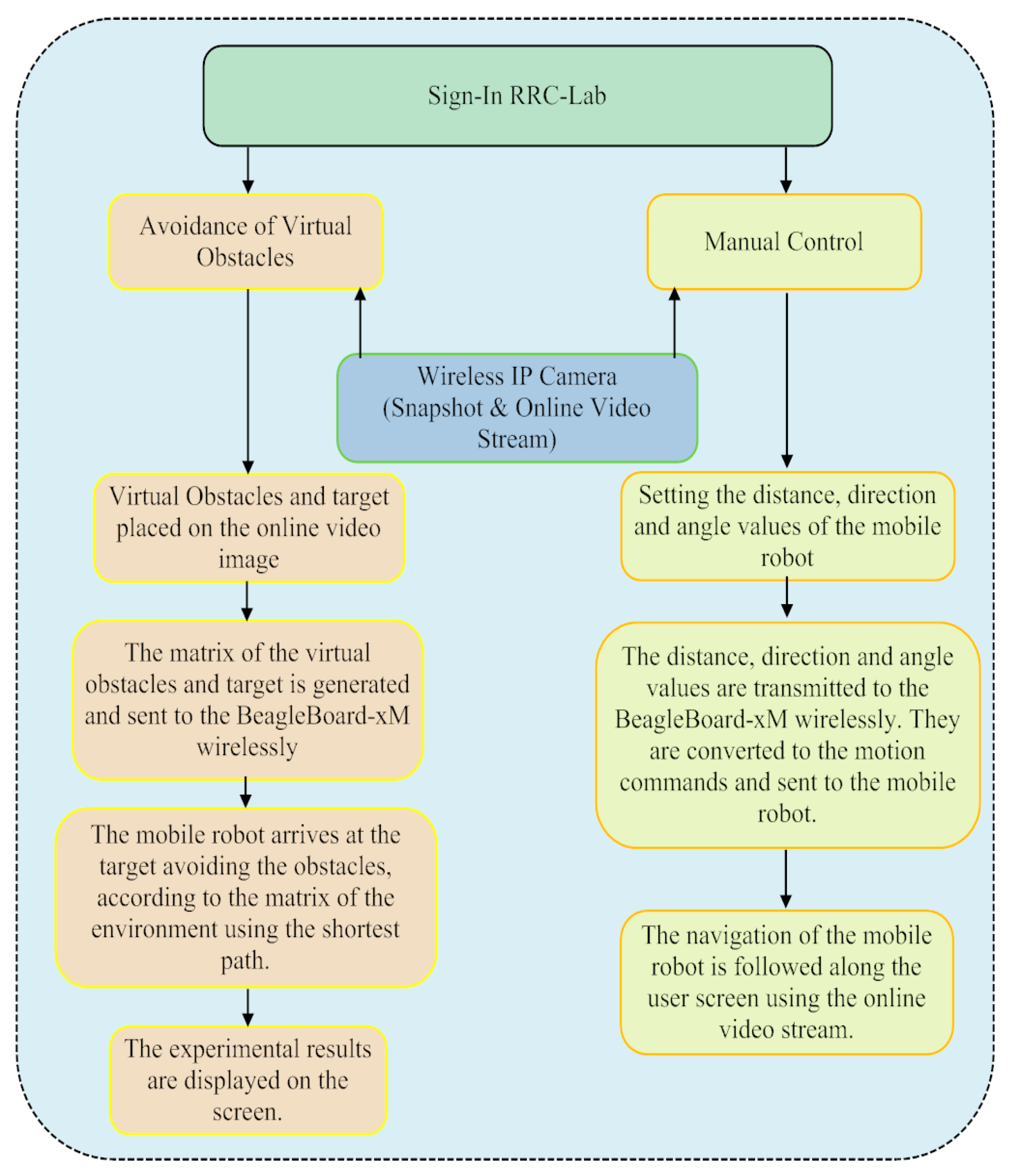
In this setup, network communication is realized via a wireless modem. A server is prepared by installing Apache web server and PostgreSQL database server onto the PC in the web interface module. The RRC-Lab platform provides local and internet broadcasts via an Apache web server by using the HTTP communication protocol. The flow chart of the RRC-Lab user interface is demonstrated in Figure 3.
The user can access this platform over the internet. The user should register on the system first. After the registration is approved by the system manager, the user can perform their experiments employing the system during the stated time period. Since the experimental setup is single, it can be used by only one user at any given time. The membership data of the users are kept in the PostgreSQL database server tables. RRC-Lab visitors can have access to detailed technical knowledge of the system components using RRC-Lab user’s manual. Additionally, when the user logs in,
- The experimental environment can be seen online.
- The real time experiment can be performed utilizing the virtual obstacle avoidance web interface in the real research laboratory environment.
- Remote and real time control of the robot can be achieved using the manual control web interface.
2.1.1. Virtual Obstacle Avoidance Web Interface
This interface lets its users practice on obstacle avoidance experiments in a real laboratory environment, locating the virtual obstacles and the target. The users can also observe the robot using the online video stream.
The RRC-Lab user decides the locations of the virtual obstacles and the target on the online video stream utilizing this interface. Since the virtual obstacles and target are located on the video stream, there is no real obstacle, target or any other object in the laboratory environment except the robot. Thus, an experimental laboratory platform is constructed by combining a virtual and real laboratory environment. While the web interface is providing a virtual simulation environment, the robot’s physical motion is enabled in the laboratory environment.
After the user positions the virtual obstacles and the target, the necessary parameters are sent to the BeagleBoard-xM through the Apache web server utilizing the wireless modem. The BeagleBoard-xM controls the robot according to the given parameters and transmits the results back to the user screen. The user can watch the online video of the laboratory environment, including the robot.
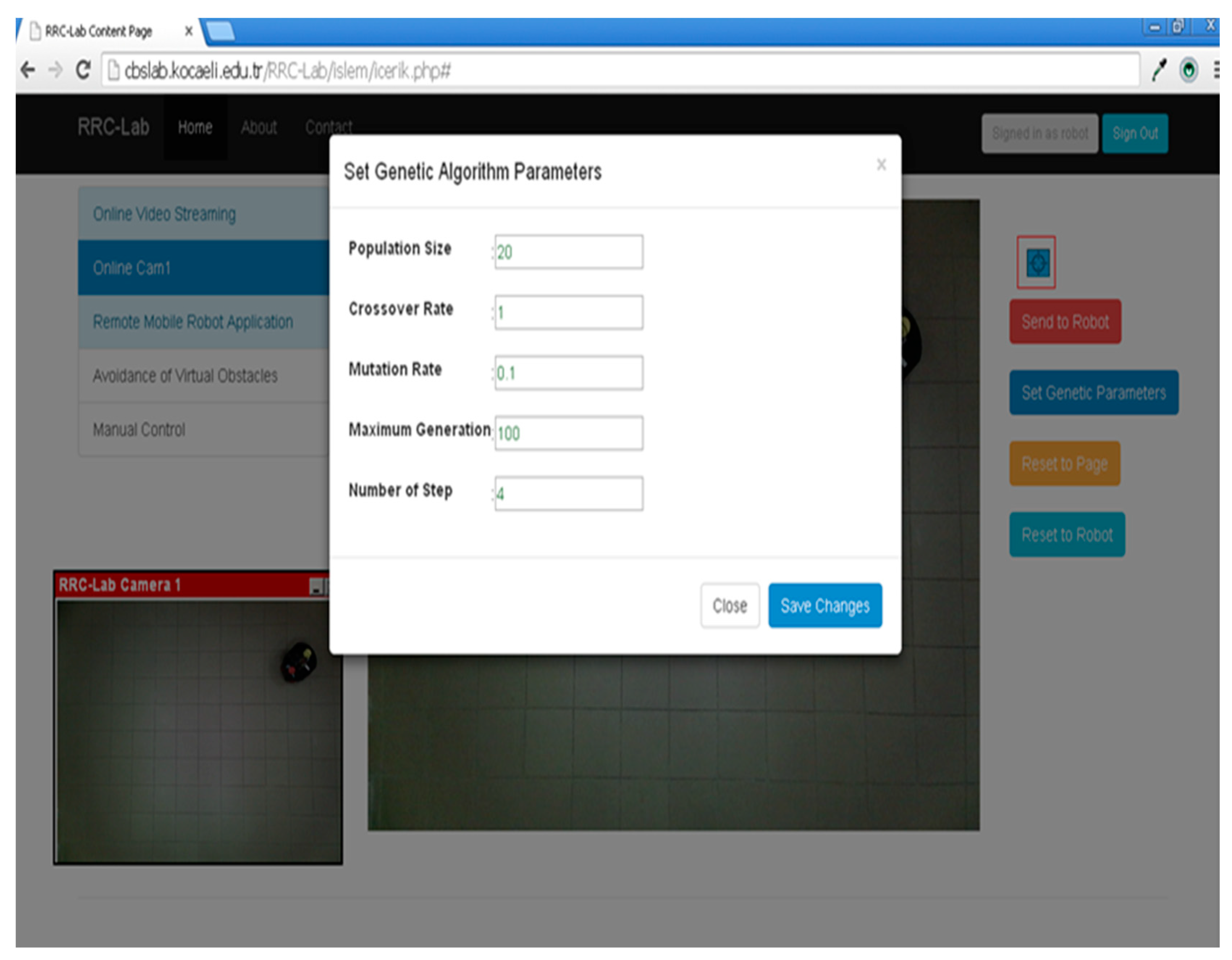
GA is employed for path planning of the robot. GA parameters, population size, crossover rate, mutation rate, maximum generation and number of steps can be sent to the program by using the user web interface or console screen. The default values of the GA parameters are; population size = 20, crossover rate = 1, mutation rate = 0.1, maximum generation = 100, number of steps = 4. These parameters can be changed using the interface seen in Figure 4.
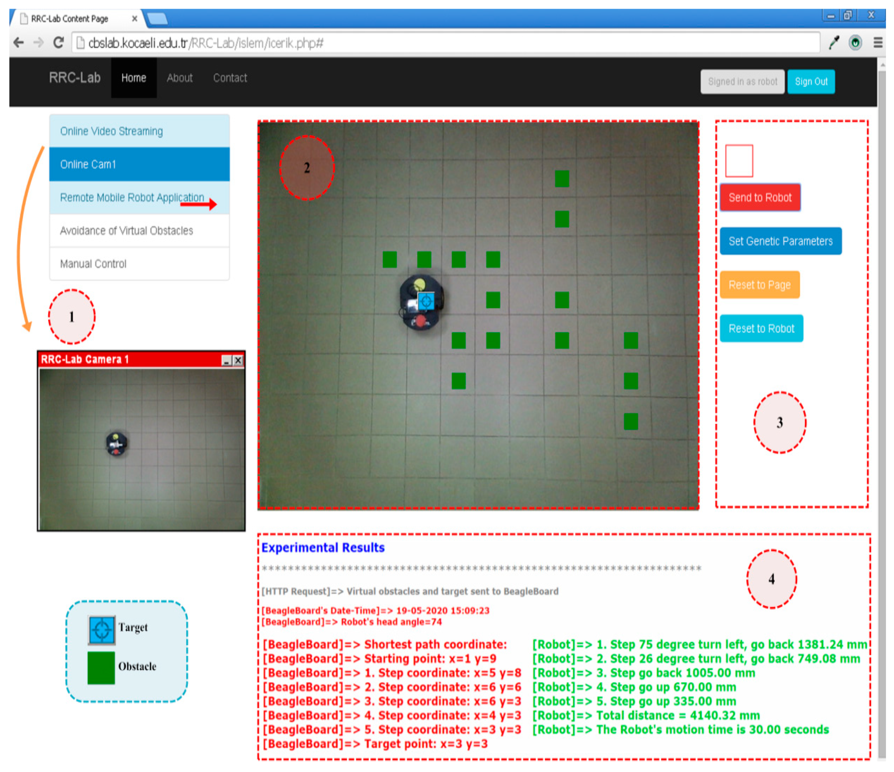
The experimental results of the virtual obstacle avoidance are shown in Figure 5. The tasks of the numbered regions in Figure 5 are:
- RRC-Lab camera 1: When online Cam1 is clicked, a video screen of the laboratory environment pops up. This screen lets the user see the real laboratory environment.
- When the avoidance of virtual obstacles interface under remote mobile robot applications section is clicked, the page content in number 2 is viewed dynamically. The video stream of the laboratory environment taken from the wireless IP camera is monitored in this area. Green obstacles are located on the online video stream by left clicking the mouse. If the mouse is left clicked on the same position second time, the green obstacle is removed. The blue target is placed anywhere on the online video image by the mouse drag-and-drop method from the area numbered as 3. If the user places an obstacle or a target on the robot by accident, the system gives a warning message to the user.
- Target, send to robot, set genetic parameters, reset to page, and reset to robot buttons are situated in this region.
- The data, including the locations of the obstacles and the target, is carried to the BeagleBoard-xM by wirelessly clicking the send to robot button. Then, the robot arrives at the target avoiding the obstacles in accordance with the user’s demand. The user can observe the robot’s movements simultaneously. If it is demanded, the set genetic parameters button is clicked and the parameters can be modified and their effect on the produced shortest path of the GA is tested. The reset to page button is applied to clear the virtual obstacles and the target. The reset to robot button initializes the robot.
After the robot completes its navigation, the results are shown in this section. The red texts show the results of the robot’s path produced by the GA. Green texts present the total distance and time of the robot’s navigation and the motion commands.
2.1.2. The Manual Control Web Interface
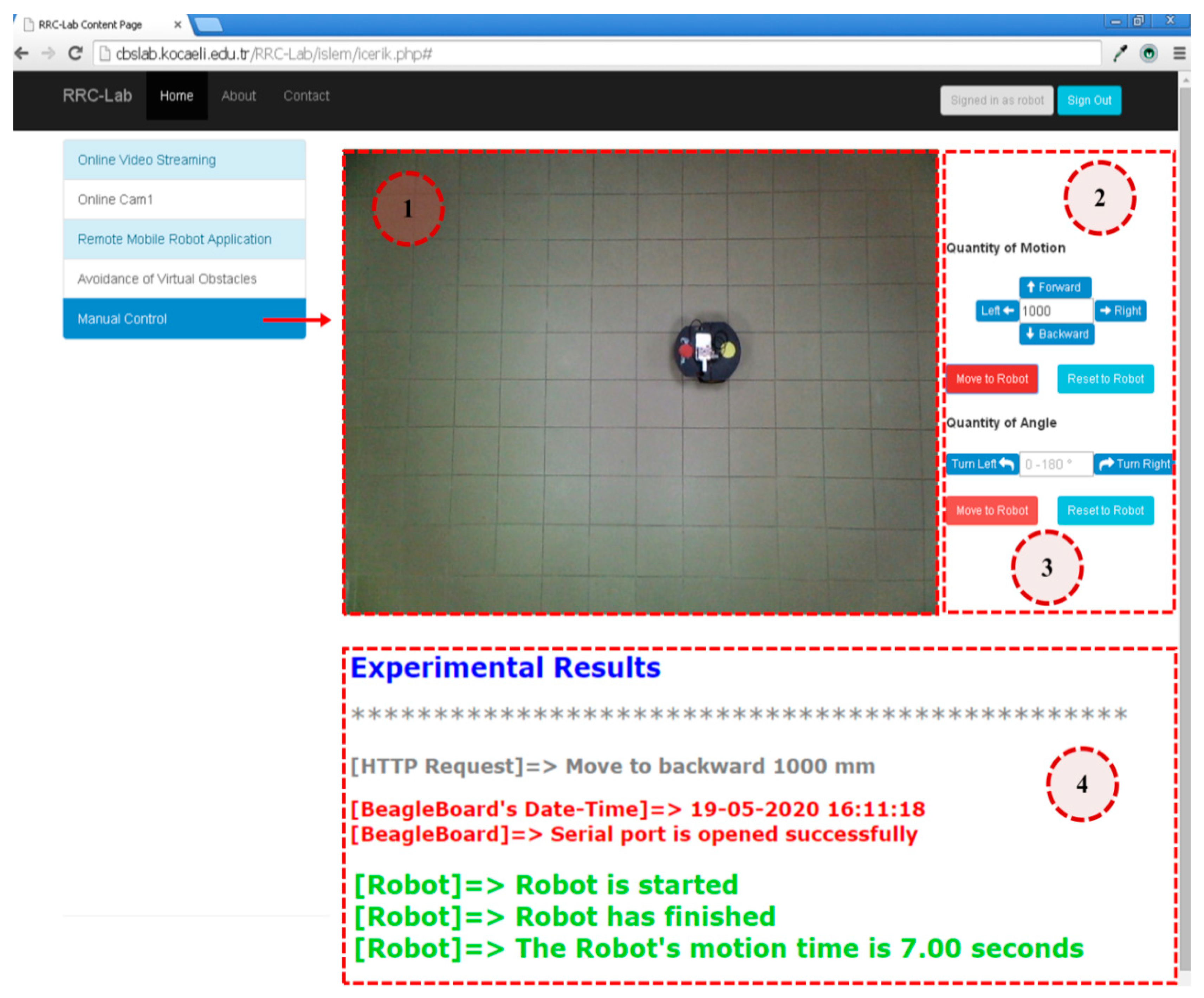
This interface allows the user to control the robot manually through the internet. The user can observe the motion of the robot utilizing the online video stream. Forward, backward, right, left commands with a distance between 0 and 1000 mm are sent to the robot through this interface. The rotation angle command to the left or right between 0 and 180° can also be transmitted via this interface. The motion direction and the angle values of the robot are transferred wirelessly to the BeagleBoard-xM through the modem. The BeagleBoard-xM causes the robot to move in accordance with the given direction and angle values. After the robot completes its navigation, the results are transmitted back to the user screen. The manual control web interface is given in Figure 6.
The functions of the numbered sections in Figure 6 are:
- When the manual control button is clicked, the page content rises in the area shown by the red arrow dynamically. The robot’s motion in the experimental environment is viewed by the wireless IP camera in this section.
- The robot goes forward in the direction and the distance defined by the user in this section. The direction can be forward, backward, right or left. If the direction is stated as right or left, the robot turns 90° to the given direction. The robot can be sent in the desired direction and distance by stating the direction and the distance and clicking the move to robot button. During this motion, the robot’s navigation is followed using the online video stream. The reset to robot button initializes the robot.
- This section is developed to direct the robot to 0–180° right or left. The robot can be transported to the desired point of the indoor laboratory environment.
Experimental results generated by the BeagleBoard-xM are viewed in this section. The request from the web server, the system clock of the BeagleBoard-xM, the status of the serial port, the start and end of the robot’s motion and the motion duration are displayed in this section.
2.2. The Mobile Robot Control Module
The components included in this module and the communication structures are presented in Figure 7. The BeagleBoard-xM and the Pioneer P3-DX, communicating with each other through RS-232 serial port, compose this module.
The Ångstrom operating system runs on the BeagleBoard-xM. The BeagleBoard-xM performs a wireless communication with the wireless modem via the wireless network adapter. HTTP requests coming from the RRC-Lab platform to the BeagleBoard-xM are transmitted to the LightHTTPd web server installed on the operating system. The given data are processed and sent to the developed program. This program generates the control commands for the appropriate angle and distance in accordance with the given parameters using the OpenCV and GA. These commands are transmitted from the serial port of the BeagleBoard-xM to the serial port of the robot. The robot navigates in accordance with the given angle and distance commands. After the robot completes its navigation, the results of the procedure steps are posted backwards to the PC web server via the LightHTTPd web server. The results as HTTP response are transferred wirelessly to the RRC-Lab platform user’s screen.
In this study, the motion planning and manual control programs are developed on the BeagleBoard-xM in the C programming language. The BeagleBoard-xM is the basic component of this module.
The robot’s motion is provided using two parameters taken from the console or the web interface in the manual control program. The parameters can be either the distance with the direction or the distance with the angle.
The open source library, OpenCV is used with the C programming language in this program. This program enables the robot to arrive at the virtual target using the shortest path by avoiding the virtual obstacles via the web. It is processed by the HTTP request coming from the LightHTTPd server. The environment matrix and GA parameters are sent to the program. GA is applied to create the shortest path from the starting point to the target. GA parameters such as iteration number, number of steps, mutation and crossover rate and population size, and the locations of the virtual obstacles and the target are taken by this program. The given location values are placed in the matrix of the environment.
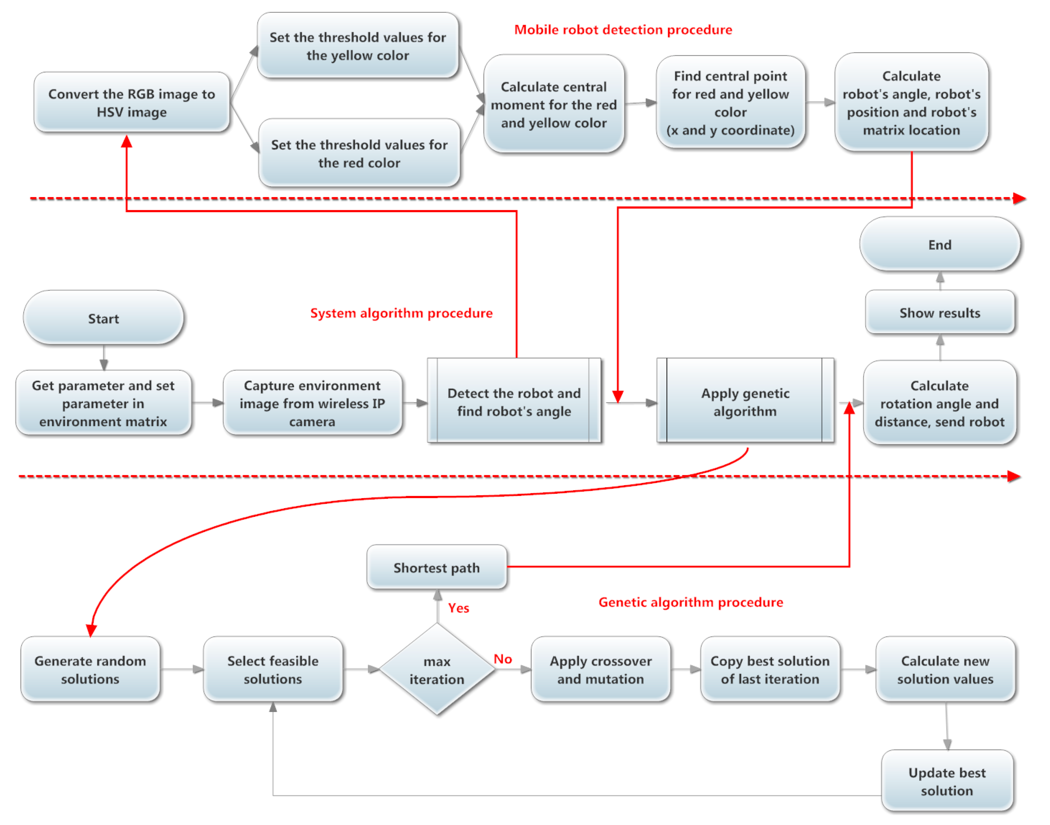
Figure 8 illustrates the flowchart of the mobile robot motion planning program. The open source library, OpenCV, is used with the C programming language in this program. This program enables the mobile robot to arrive at the virtual target by the shortest path avoiding the virtual obstacles via the web. It is processed by the HTTP request coming from the LightHTTPd server installed on the BeagleBoard-xM.
The environment matrix and GA parameters are sent to the program. GA is applied to create the shortest path from the starting point to the target. GA parameters such as iteration number, number of steps, mutation and crossover rate and population size, and the locations of the virtual obstacles and the target are taken by this program. The given location values are placed in the matrix of the environment.
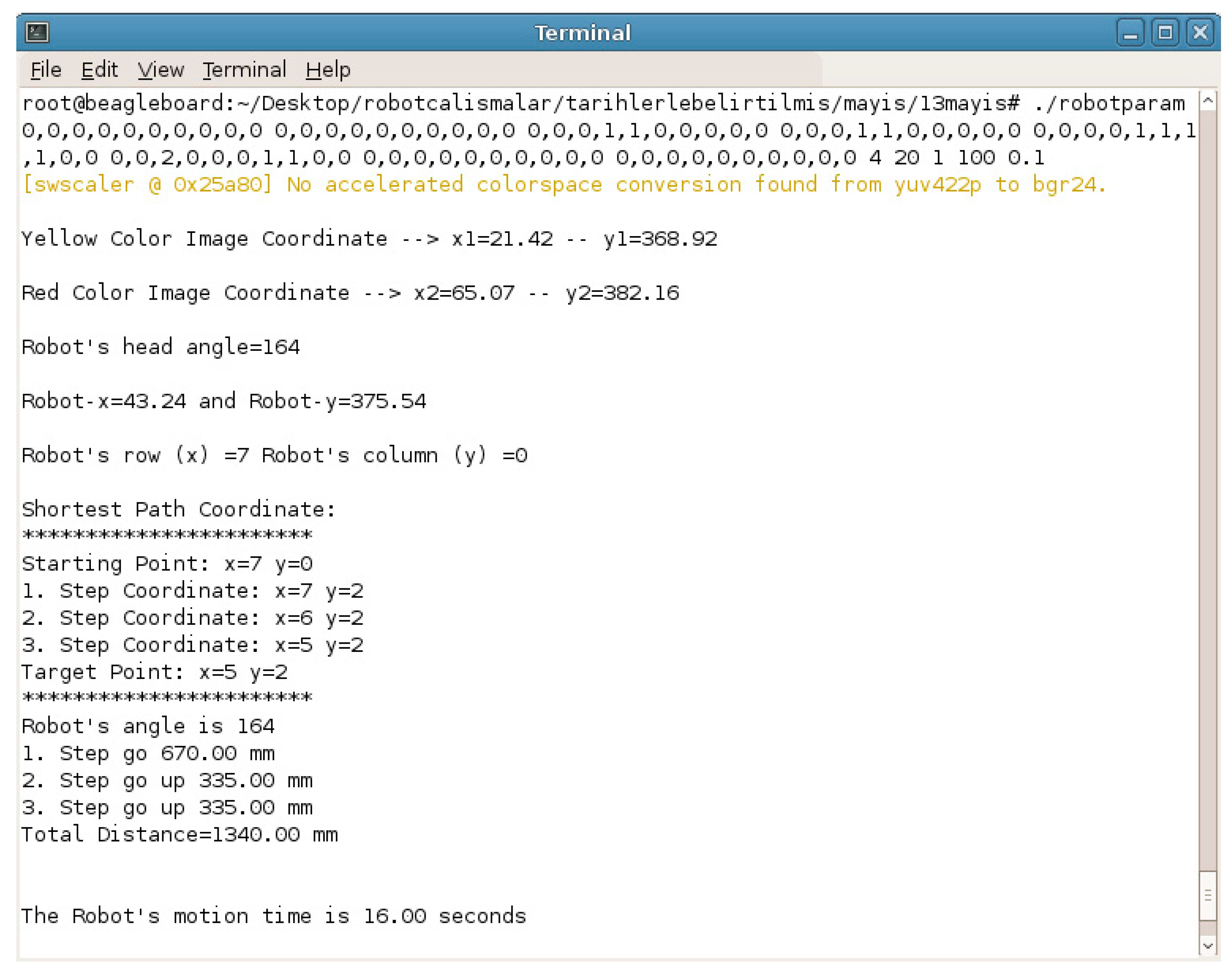
This program is also operated by a remote desktop connection. Figure 9 illustrates the remote desktop connection console screen, including the results. This program gives these outputs: the head angle and the center coordinates of the red and yellow colors and the robot in the real image, the location of the robot in the matrix of the environment, the shortest path coordinates, the operations of the robot, total distance and motion time.
2.2.1. Path Planning for the Mobile Robot
A heuristic method, GA is used for path planning of the robots [22,23,24,25]. GA is an optimization algorithm capable of performing a global search and exploring the search area. GA works best on functions defined on complex systems and discrete structures. GA is used to produce the best result for solving optimization and search problems. While developing the most suitable solutions, GA can make parallel searches in the working environment and reach the best solution faster. GA is frequently applied in a wide variety of application areas such as optimization, economics, image processing, artificial intelligence and robot trajectory and routing problems. GA discovers the global minimum better by avoiding the local minimum while performing a global search operation. GA is used to find the shortest path solution by avoiding the obstacle for the purpose of path planning in complex environments with fixed or mobile obstacles. Thus, GA proposes the most optimal solution to contribute to the path planning of robots.
The random solution set, which includes the solution to the path planning problem of the mobile robot, is generated for GA. Nonaccepted solutions are possible in this random solution set. These solutions are discarded first. It is controlled if the iteration number sent from the web interface or the console screen is achieved or not. If it is not yet achieved, crossover and mutation processes are applied. The best solution found in the previous iteration is transferred to the next iteration. Thus, it is guaranteed that the best solution up to then is kept. A new calculation is executed for the individuals subjected to crossover and mutation operations. At the conclusion of this calculation, the appropriate solutions are selected and an update process is performed for the best solution. This process continues up to the maximum iteration number. When the maximum iteration number is reached, the best solution up to that time is obtained.
2.2.2. Location of the Mobile Robot
It is essential to determine the location, direction and the angle of the robot. The BeagleBoard-xM communicates with the wireless modem via the wireless network adapter and takes the image of the laboratory environment from the wireless IP camera. This image is processed on the BeagleBoard-xM by using the OpenCV, C programming language and image processing techniques.
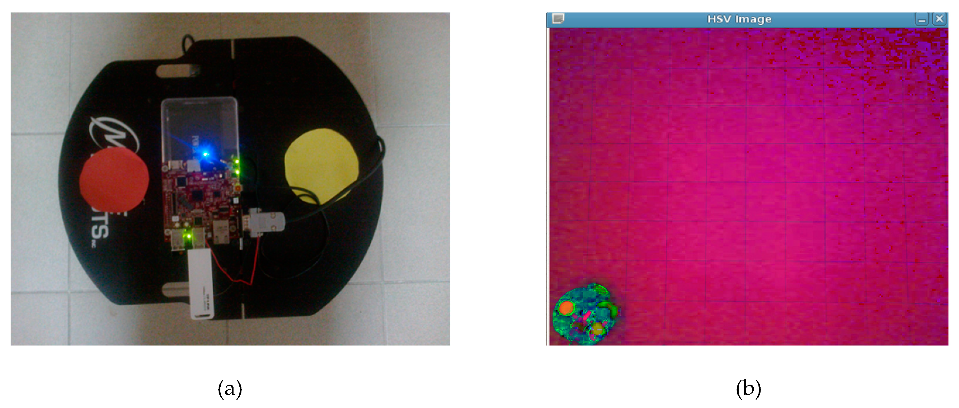
Color detection is applied to obtain the direction of the robot. Red and yellow colors are placed on the robot to determine the direction, angle and location of the robot. While yellow represents the head of the robot, red stands for the back side of the robot as seen in Figure 10a. The BeagleBoard-xM is located between the two colors.
The image of the laboratory environment taken by the wireless IP camera is converted to the HSV color space using the equations given in [22,25,26,27,28]. The HSV image is shown in Figure 10b.
Two different pictures are created by utilizing the HSV image. One of them shows only the yellow colored objects while the other includes only the red colored objects as seen in Figure 11a,b respectively. The corresponding color values in this range are left as white, while other color values are left as black.
There are various methods of object recognition in the literature. Moment invariants algorithm was used in the developed RRC-Lab system. The RRC-Lab system was implemented on a BeagleBoard-xM as a single board computer. Therefore, the methods and techniques to be used must be selected according to the characteristics and capabilities of BeagleBoard-xM. In this case, when developing an algorithm, criteria such as low consumption of system resources, low complexity and fast operation are taken into consideration. While evaluating moment invariants algorithm in the RRC-Lab system, it was decided to use it due to its ease of use, low complexity, low system resource consumption and rapid results. In the RRC-Lab system, the methods and techniques used were evaluated according to these criteria and the appropriate ones were selected. Furthermore, the moment invariants algorithm, one of the most effective methods to extract descriptive features for object recognition applications, is employed to determine the coordinates of the red and yellow colors [22,29]. The moment invariants algorithm is applied after leaving the red and yellow colored objects alone in the image. The coordinates of the two colors are derived to determine the robot’s angle, direction and location in the matrix. The moments are computed using the Equation (1). M x N refers to the size of the image and the image (i,j) is the related point of the digital image. In Equation (1), i = 0, 1, 2,…… M − 1; j = 0, 1, 2,…… N − 1 and p, q = 0, 1, 2, … [22,30,31,32,33,34,35].
m00, m10, m01 calculated using Equation (1) are utilized to derive the x and y values, shown in Equation (2), which are employed as the coordinates of the red and yellow colors.
x1 and y1 are the coordinates of the red, while x2 and y2 are the coordinates of the yellow. Equation (3) is used to achieve the starting angle of the robot (θS).
Since yellow corresponds to the front and red shows the back side of the robot, the starting angle is updated according to the positions of the coordinates of the two colors and the starting angle is calculated in the direction of the (+x) coordinate. The relations given in Equation (4) are utilized during the update process of the angles (θS).
Besides, the distance between the centers of two colors is determined in order to detect the location of the robot in the grid-based map. The location of the robot is specified as the coordinates of the midpoint between two colors.
The starting and the next location of the robot are defined by the matrices given in Equation (5). RS includes the starting coordinates and angle of the robot.
and represent the x, y coordinates of the starting location while θS shows the starting angle. Similarly, RS+1 contains the coordinates and angle of the robot’s next location.
The distance (RDist) between current and next location of the robot is calculated as Euclidean distance using the Equation (6).
The angle (θR) which the robot should turn to navigate to the next location is found with the Equation (7).
Equation (8) presents the differences of x and y coordinates between the robot’s current and next coordinates.
The direction which the robot should turn while navigating between two points is calculated as when the robot consumes the least energy. For this, RΔx, RΔy, θS and θR values and the equations given in Table 1 are used. In this Table, B: Backward, F: Forward.
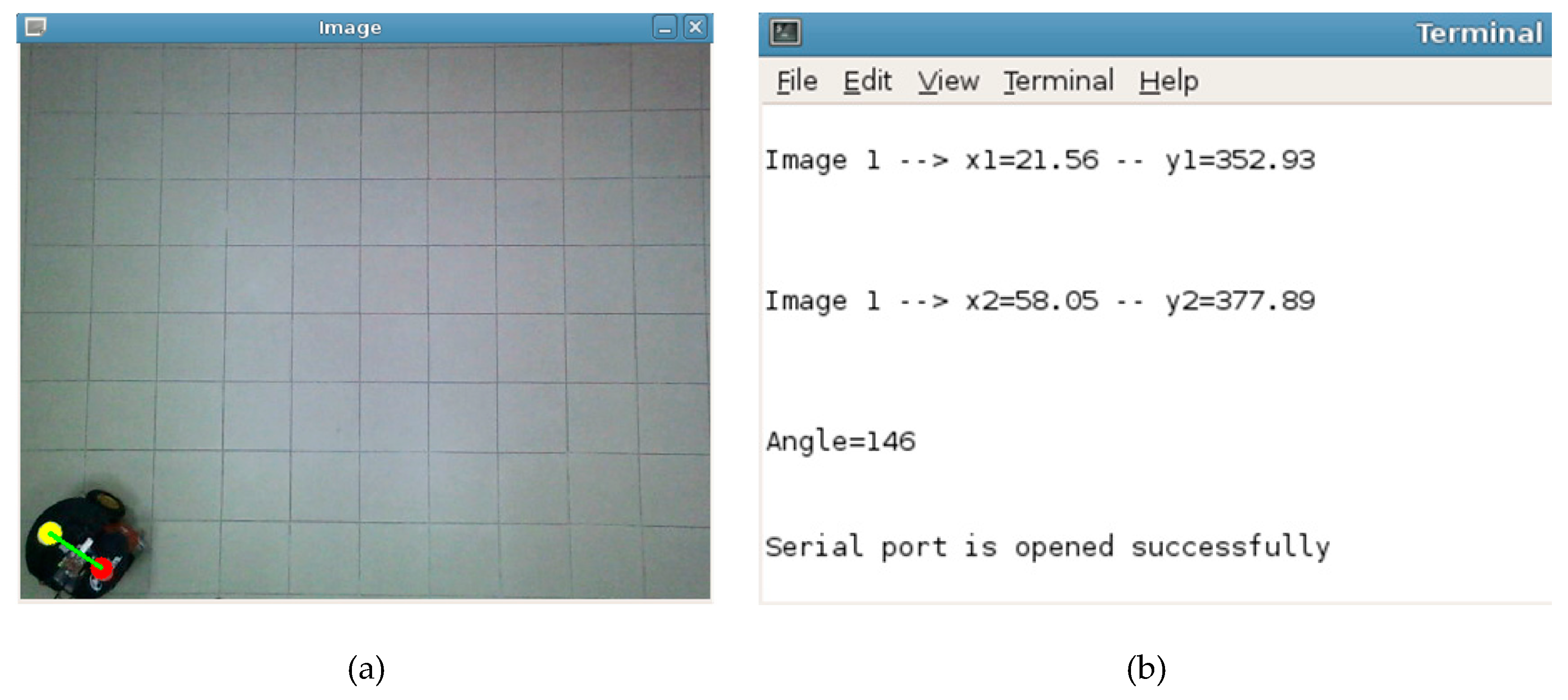
Figure 12a illustrates the virtual line drawn between the centers of the red and yellow colors along with the robot. The terminal screen presenting the results of the program running on the BeagleBoard-xM is depicted in Figure 12b. The coordinates of the red and yellow colors and the angle between the virtual line and (+x) axis are given in this figure.
2.2.3. The Motion of the Mobile Robot
After determining the robot’s location and angle in the grid-based matrix, it enabled the robot to arrive at the target by avoiding the obstacles using the path planning algorithm. The route of the robot is determined utilizing the solution generated by the GA path planning algorithm. This route includes the direction, angle and the distance information for the robot’s navigation.
The Equations (3) and (7) and the equations in Table 1 are used to estimate the angle θ for the robot shown in Figure 13. The length, RDist is calculated by applying Equation (6). θ, θS, θR and RDist should be updated for each step of the generated path.
The rotation angle should be applied to the robot first. While the robot is rotated with the calculated angle, its angle at the starting point should also be taken into consideration. Therefore, both the starting point angle of the robot and the angle between two points are obtained and the robot is able to navigate following the shortest path to the target.
The communication between the robot and the BeagleBoard-xM is achieved via the serial port. Foremost, the angle and then the distance values obtained are transmitted to the robot through the serial communication interface. While the robot is moving towards the target, the same processes are repeated one after the other for the next coordinates the robot arrives at. Finally, the covered distance of the robot and the entire spent time are calculated.
3. Experimental Study
The user logged into the RRC-Lab web-based platform can access the virtual obstacle avoidance web interface and the manual control web interface. The RRC-Lab user can achieve remote control of the robot by providing the communication for the components via the wireless modem. The user can always access the online video stream of the laboratory environment via the wireless IP camera. These experimental studies can be performed with the robot through the BeagleBoard-xM. The experimental results are sent to the Apache web server, installed on the PC via the LightHTTPd web server. The RRC-Lab user logged into the Apache web server can monitor these results in their web browser. So, the robot can be controlled remotely and monitored using the developed web-based platform.
The robot may have any location covered by the wireless IP camera in the laboratory at the beginning of the experiment. While performing a motion planning experiment with this platform, the necessary parameters are applied utilizing the set genetic algorithm parameters window first. The default parameter values are applied in the experiments presented in this work.
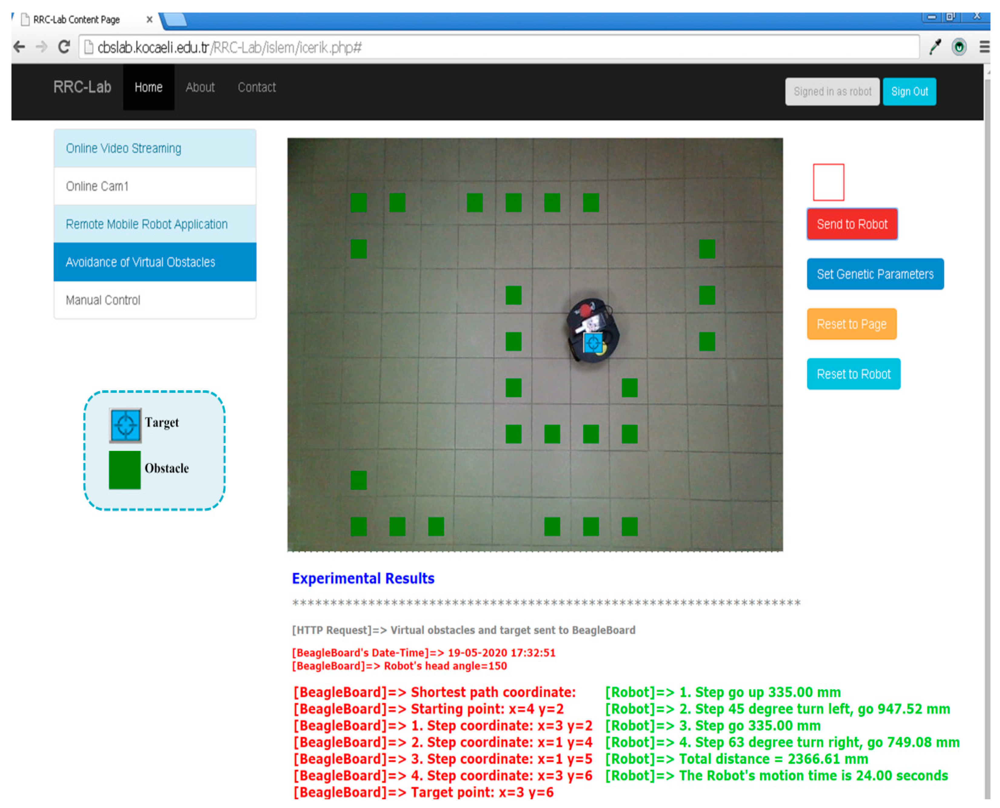
After setting the GA parameters, the user can locate virtual obstacles anywhere on the online video stream. Then, a virtual target existing at the virtual obstacle avoidance web interface is dragged and dropped wherever desired. The screen, including the virtual obstacles and target is shown in Figure 14. The send to robot button is clicked. Then the Apache web server sends all these data to the LightHTTPd web server via the wireless modem. These parameters are employed by the motion planning control program. The robot arrives at the target navigating in the direction of the motion control commands generated by this program. After the robot completes its navigation, the obtained results are transferred to the PC Apache web server via LightHTTPd web server and monitored on the user interface screen as indicated in Figure 15.
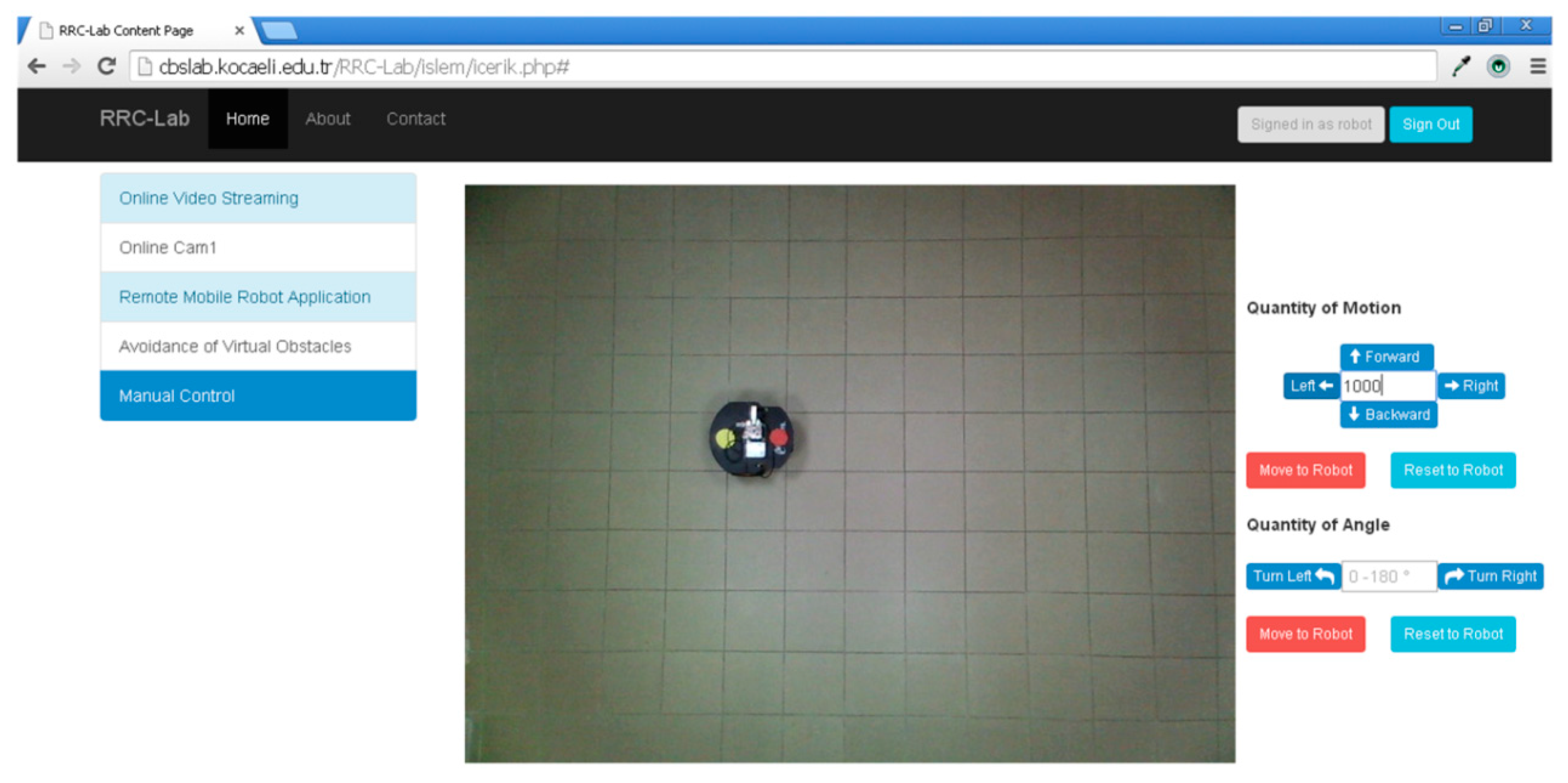
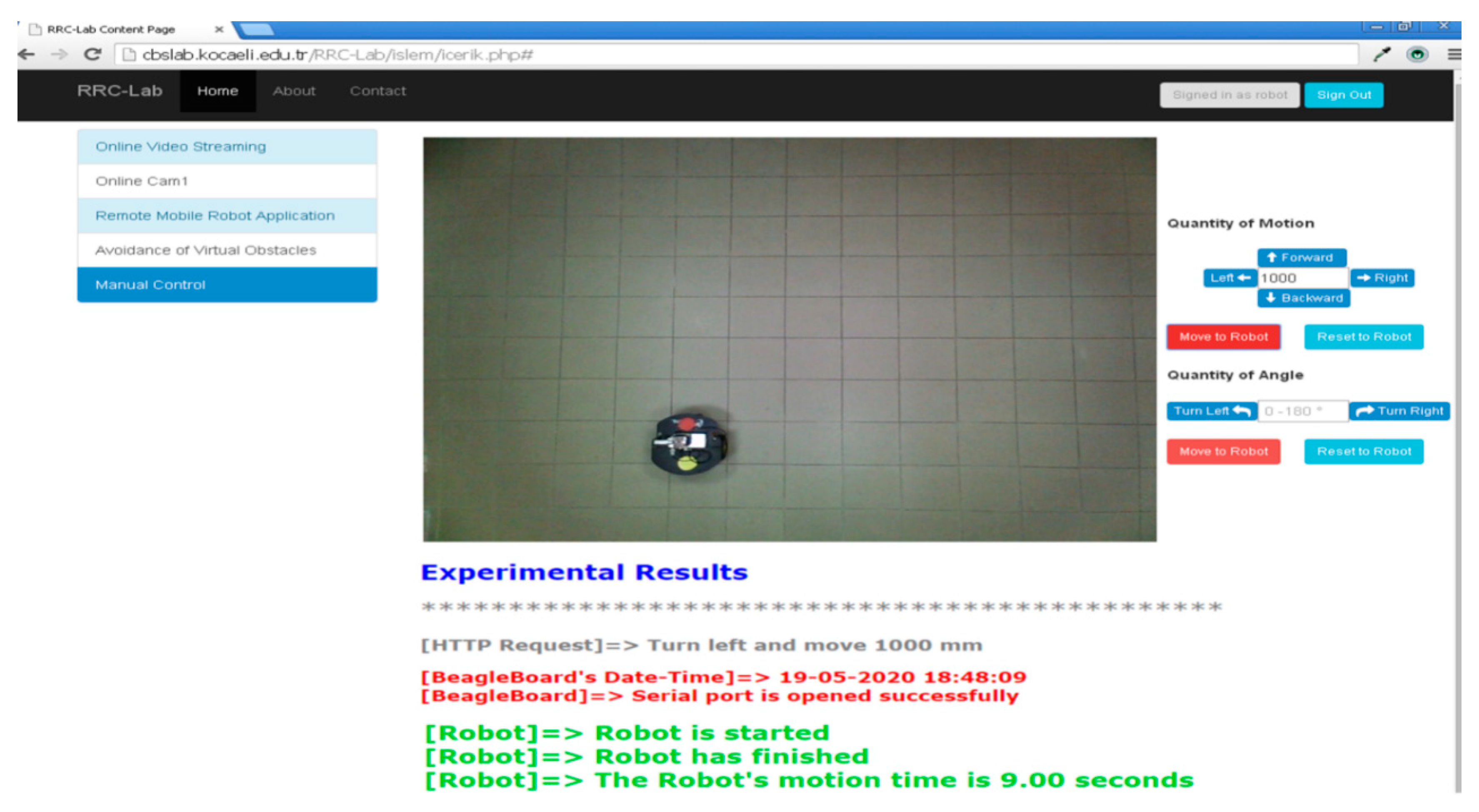
If a virtual obstacle or target is located on the robot by accident, a warning message pops up. At the beginning of the manual control experiment, the robot is situated as seen in Figure 16. The distance is entered as 1000 mm and then the left button is click. Then the robot turns 90° left and goes forward 1000 mm. The experimental results are demonstrated in Figure 17.
4. Results and Discussion
The usability and performance of the RRC-Lab was evaluated by 19 students in the information system engineering departments of Kocaeli University. After the students use the RRC-Lab system, they are asked to answer a ten-statement Likert scale survey. The ten-statement Likert scale (1 = strongly disagree, 2 = disagree, 3 = indifferent, 4 = agree, 5 = strongly agree) survey along with results are listed in Table 2. The statements in the survey include some questions contained in the system usability scale (SUS) survey developed by Brooke [36] and some specific questions about the RRC-Lab system component.
The aim of the survey included students’ opinions about RRC-Lab, the solutions of genetic algorithm-like optimization techniques in mobile robot obstacle avoidance problems and requirements of similar courses. When all statements are generally examined, the mean score of statements is between 3.68 and 4.74 out of 5. When these statements are examined as a whole, about 85.47% of the students have thought that the RRC-Lab is easy to use, efficient and sufficient.
The mean score of the first statement “I think that The RRC-Lab is easy to use.” was 4.74 over 5, and approximately 94.73% of the students agreed with the question. According to the second and third statements’ mean scores, the effect of the RRC-Lab mobile robot obstacle avoidance problem and navigation problem has been examined, and about 74.74% of the students were in agreement with these questions. According to the average scores of the fourth and fifth questions, the relationship between genetic algorithm and the mobile robot was examined, about 84.21% of the students have agreed in these statements. The average score of the sixth statement was 4.16 out of 5, and about 83.15% of the students agreed with the question. Students were pleased to see many components integrated into the RRC-Lab. According to the average value of the seventh question, the students thought that it was 91.57% effective and efficient to practice after receiving technical information about the mobile robot and genetic algorithm. According to the average scores of the eighth and ninth statements, about 88.94% of the students agreed with these questions. From the average scores of the eighth and ninth statements, it is seen that about 88.94% of the students agreed with these questions. According to these statements, students want to integrate different optimization techniques into the RRC-Lab system and to implement a remote controlled virtual lab in different courses. According to the last statement mean score, about 89.47% of students are able to use the RRC-Lab system quickly.
The survey results show that the RRC-Lab system allows students to learn mobile robot obstacle avoidance problems and the genetic algorithm quickly, effectively and efficiently. Especially after giving technical information to the students, it is more effective to examine the operation of the mobile robot using the remote controlled laboratory system.
Components contained in the developed RRC-Lab system are in a modular structure and each module communicates with each other. Many experimental studies show that the components have limited and acceptable delay times which is on average milliseconds for each component. Since the inputs taken from the web interface have specifications suitable for the components that make up the system, they are easily and quickly performed. In the developed system, the component performs its own function according to the incoming inputs and after completing its function, transmits the required information to the next component. The components of the system are designed in a modular structure and the delays that may occur are minimized as much as possible. As a result, when the developed RRC-Lab is analyzed for time delay, students do not have problems in obtaining the results of the mobile robot obstacle avoidance experiment. For instance, BeagleBoard-xM gets the request from the server and it takes less than one second to generate the grid-based map and the shortest path to the target.
5. Conclusions
The RRC-Lab web-based platform developed in this work, allows the user to perform real time experiments of path planning and avoiding virtual obstacles using the robot situated in the physical laboratory environment. Thus, this work provides a platform combining the physical laboratory environment with the virtual laboratory. The experimental studies with the mobile robot can be practiced without having a mobile robot, physical obstacles or target through the internet. This platform enables sharing the mobile robot with no expense and lets the user overcome the requirement of going to the laboratory. The only necessary thing is a PC with an internet connection and a web browser without needing to install any other programs. Hence, this platform brings the laboratory environment to the user’s computer.
A low-cost platform, including open source software and BeagleBoard-xM, is designed in this study. Therefore, no license or cost problem is encountered. A modular and flexible structure is built on this work. So, the current devices used in these modules can be replaced with the new ones such as any other single board computer or any other robot. Thus, the cost of the system can be minimized according to the hardware or the devices used.
The direction and angle of the mobile robot are determined utilizing the image taken from the wireless IP camera mounted to the ceiling. The mobile robot prefers the shortest way to arrive at the target wherever the virtual obstacles or the target are located. The mobile robot navigates using the narrowest angle while it is turning to any side. Therefore, the angle and the distance, which the mobile robot uses to navigate, are optimized and the energy saved by the mobile robot is supplied.
According to the survey, the technical knowledge given to students is more useful and effective when supported by the RRC-Lab. Furthermore, the results obtained in the study can allow computer engineers and lecturers to simulate development or at least use remote control and monitoring laboratory tools for engineering educational purposes.
In the RRC-Lab system, the genetic algorithm optimization technique was used to solve the path planning problem of the mobile robot. In future studies, other optimization techniques will be added to the RRC-Lab system and students will be provided with different algorithms. Thus, students will be able to compare the results of different algorithms. In addition, new sensors such as laser and sonar will be added to the mobile robot and the development of the RRC-Lab project will be provided.
A cheap, adaptable, flexible and useful infrastructure for various applications is proposed with this platform. This infrastructure can be amended with different applications in future surveys.
Author Contributions
System design, S.S. and Ö.Y.; methodology, S.S.; software, S.S.; web design, Ö.Y.; investigation, S.S.; writing—original draft preparation, S.S. and E.D.B.; writing—review and editing, S.S. and E.D.B.; supervision, E.D.B. All authors have read and agreed to the published version of the manuscript.
Funding
This research received no external funding.
Acknowledgments
Kocaeli University Scientific Research Projects Unit supported this study with project number BAP 2013/68HDP.
Conflicts of Interest
The authors declare no conflict of interest.
References
- Guimarães, E.; Maffeis, A.; Pereira, J.; Russo, B.; Cardozo, E.; Bergerman, M.; Magalhães, M.F. REAL: A Virtual Laboratory for Mobile Robot Experiments. IEEE Trans. Educ. 2003, 46, 37–42. [Google Scholar] [CrossRef]
- Šafaric, R.; Truntic, M.; Hercog, D.; Pacnik, G. Control and Robotics Remote Laboratory for Engineering Education. iJOE Int. J. Online Eng. 2005, 1, 1–8. [Google Scholar]
- Wei, W.; Pan, Y.; Furuta, K. Internet-based Tele-Control System for Wheeled Mobile Robot. In Proceedings of the Mechatronics and Automation, 2005 IEEE International Conference, Niagara Falls, ON, Canada, 29 July–1 August 2005; pp. 1151–1156. [Google Scholar]
- Dinelescu, I.; Popescu, D.; Predescu, A. Remote Learning Environment for Visual Based Robot Navigation. In Proceedings of the EAEEIE Annual Conference, Tallinn, Estonia, 29 June–2 July 2008; pp. 26–30. [Google Scholar]
- Popescu, D.; Selisteanu, D.; Dinulescu, I.; Popescu, L.C. Web based Telematics Application for Robotics. In Proceedings of the 2008 The Third International Multi-Conference on Computing in the Global Information Technology (iccgi 2008), Athens, Greece, 27 July–1 August 2008; pp. 19–24. [Google Scholar]
- Mester, G. Wireless Sensor-Based Control of Mobile Robots Motion. In Proceedings of the 2009 7th International Symposium on Intelligent Systems and Informatics, Subotica, Serbia, 25–26 September 2009; pp. 81–84. [Google Scholar]
- Sagiroglu, S.; Yilmaz, N. Web-Based Mobile Robot Platform for Real-Time Exercises. Exp. Syst. Appl. 2009, 36, 3153–3166. [Google Scholar] [CrossRef]
- Neamtu, D.V.; Fabregas, E.; Wyns, B.; Keyser, R.D.; Dormido, S.; Ionescu, C.M. A Remote Laboratory for Mobile Robot Applications. IFAC Proc. Vol. 2011, 7280–7285. [Google Scholar] [CrossRef] [Green Version]
- Casini, M.; Garulli, A.; Giannitrapani, A.; Vicino, A. A Remote Lab for Multi-Robot Experiments With Virtual Obstacles. In Proceedings of the Advances in Control Education, Nizhny Novgorod, Russia, 19–21 June 2012; pp. 354–359. [Google Scholar]
- Liu, H.; Stoll, N.; Junginger, S.; Thurow, K. A Common Wireless Remote Control System for Mobile Robots in Laboratory. In Proceedings of the 2012 IEEE International Instrumentation and Measurement Technology Conference Proceedings, Graz, Austria, 13–16 May 2012; pp. 688–693. [Google Scholar]
- Aroca, R.V.; Gardiman, R.Q.; Golçalves, L.M.G. Web-Based Robot Programming Environment and Control Architecture. In Proceedings of the 2012 Brazilian Robotics Symposium and Latin American Robotics Symposium, Fortaleza, Brazil, 16–19 October 2012; pp. 27–32. [Google Scholar]
- Santos, C.; Manuel, M., Jr.; Espinosa, F. Adaptive Self-Triggered Control of a Remotely Operated P3-DX Robot: Simulation and Experimentation. Rob. Auton. Syst. 2014, 62, 847–854. [Google Scholar] [CrossRef]
- Antony, A.J.P.; Rajpandian, S. Web-Based Control and Monitoring of Telepresence Robot. Int. J. Innov. Res. Sci. Eng. Technol. 2014, 3, 1742–1747. [Google Scholar]
- Inanc, T.; Dinh, H. A Low Cost Autonomous Mobile Robotics Experiment: Control, Vision, Sonar, and Handy Board. Comput. Appl. Eng. Educ. 2012, 20, 203–213. [Google Scholar] [CrossRef]
- Stefanovic, M.; Tadic, D.; Nestic, S.; Djordjevic, A. An Assessment of Distance Learning Laboratory Objectives for Control Engineering Education. Comput. Appl. Eng. Educ. 2015, 23, 191–202. [Google Scholar] [CrossRef]
- Gil, A.; Reinoso, O.; Marin, J.M.; Paya, L.; Ruiz, J. Development and Deployment of a New Robotics Toolbox for Education. Comput. Appl. Eng. Educ. 2015, 23, 443–454. [Google Scholar] [CrossRef]
- Jara, C.A.; Candelas, F.A.; Pomares, J.; Torres, F. Java software platform for the development of advanced robotic virtual laboratories. Comput. Appl. Eng. Educ. 2013, 21, E14–E30. [Google Scholar] [CrossRef] [Green Version]
- Berenguel, M.; Rodríguez, F.; Moreno, J.C.; Guzmán, J.L.; González, R. Tools and Methodologies for Teaching Robotics in Computer Science & Engineering Studies. Comput. Appl. Eng. Educ. 2016, 24, 202–214. [Google Scholar]
- Rampazzo, M.; Cervato, A.; Beghi, A. Remote Refrigeration System Experiments for Control Engineering Education. Comput. Appl. Eng. Educ. 2017, 25, 430–440. [Google Scholar] [CrossRef]
- WebLab-Deusto. Available online: https://weblab.deusto.es/website/ (accessed on 18 May 2020).
- Go-Lab. Available online: https://www.golabz.eu/spaces (accessed on 19 May 2020).
- Solak, S. The Solution of the Mobile Robots’ Localization and Obstacle Avoidance Problem Using Single Board Computer System. Ph.D Thesis, Kocaeli University Institute of Science and Technology, Kocaeli, Turkey, 2016. [Google Scholar]
- Tuncer, A.; Yildirim, M. Dynamic Path Planning of Mobile Robots with Improved Genetic Algorithm. Comput. Electr. Eng. 2012, 38, 1564–1572. [Google Scholar] [CrossRef]
- Qu, H.; Xing, K.; Alexander, T. An Improved Genetic Algorithm with Co-evolutionary Strategy for Global Path Planning of Multiple Mobile Robots. Neurocomputing 2013, 120, 509–517. [Google Scholar] [CrossRef]
- Solak, S.; Bolat, E.D.; Tuncer, A.; Yildirim, M. A Low Cost Single Board Computer Based Mobile Robot Motion Planning System for Indoor Environments. Int. J. Intell. Syst. Appl. Eng. 2016, 4, 95–102. [Google Scholar] [CrossRef]
- Pekel, J.F.; Vancutsem, C.; Bastin, L.; Clerici, M.; Vanbogaert, E.; Bartholomé, E.; Defourny, P. A Near Real-Time Water Surface Detection Method Based on HSV Transformation of MODIS Multi-spectral Time Series Data. Remote Sens. Environ. 2014, 140, 704–716. [Google Scholar] [CrossRef] [Green Version]
- Solak, S.; Bolat, E.D. Real Time Industrial Application of Single Board Computer Based Color Detection System. In Proceedings of the 2013 8th International Conference on Electrical and Electronics Engineering (ELECO), Bursa, Turkey, 28–30 November 2013; pp. 353–357. [Google Scholar]
- Solak, S.; Bolat, E.D. Distance estimation using stereo vision for indoor mobile robot applications. In Proceedings of the 2015 9th International Conference on Electrical and Electronics Engineering (ELECO), Bursa, Turkey, 26–28 November 2015; pp. 685–688. [Google Scholar]
- Premaratne, P.; Premaratne, M. Image Matching Using Moment Invariants. Neurocomputing 2014, 137, 65–70. [Google Scholar] [CrossRef]
- Rao, C.S.; Kumar, S.S.; Mohan, B.C. Content Based Image Retrieval Using Exact Legendre Moments and Support Vector Machine. Int. J. Multimed. Its Appl. IJMA 2010, 2, 69–79. [Google Scholar] [CrossRef]
- Mercimek, M.; Gulez, K.; Mumcu, V.T. Real Object Recognition Using Moment Invariants. Sadhana 2005, 30, 765–775. [Google Scholar] [CrossRef] [Green Version]
- Wang, Y.; Wang, X.; Zhang, B.; Wang, Y. A Novel Form of Affine Moment Invariants of Grayscale Images. Elektron. Elektrotech. 2013, 19, 77–82. [Google Scholar] [CrossRef]
- Papakostas, G.A.; Koulouriotis, D.E.; Karakasis, E.G.; Tourassis, V.D. Moment-Based Local Binary Patterns: A Novel Descriptor for Invariant Pattern Recognition Applications. Neurocomputing 2013, 99, 358–371. [Google Scholar] [CrossRef]
- Solak, S.; Bolat, E.D. A new hybrid stereovision-based distance-estimation approach for mobile robot platforms. Comput. Electr. Eng. 2018, 67, 672–689. [Google Scholar] [CrossRef]
- Solak, S.; Altinişik, U. A new method for classifying nuts using image processing and k-means++ clustering. J. Food Proc. Eng. 2018, 41, e12859. [Google Scholar] [CrossRef]
- Brooke, J. SUS-A quick and dirty usability scale. Usability evaluation in industry. Tay. Franc. Lond. 1996, 189, 4–7. [Google Scholar]
Figure 1.
Physical environment of the experimental setup.

Figure 2.
The block diagram of the RRC-Lab platform.

Figure 3.
The flowchart of the RRC-Lab user interface.

Figure 4.
Genetic algorithm parameters setting window.

Figure 5.
The results page of the virtual obstacle avoidance experiment.

Figure 6.
The manual control web interface.

Figure 7.
The structure of the manual control.

Figure 8.
The flowchart of the mobile robot motion planning program.

Figure 9.
Remote desktop connection screen and the results.

Figure 10.
(a) The top view of the mobile robot; (b) the image converted to the HSV color space.

Figure 11.
(a) The image containing only the yellow colored objects; (b) the image containing only the red colored objects.
Figure 11.
(a) The image containing only the yellow colored objects; (b) the image containing only the red colored objects.

Figure 12.
(a) The virtual line drawn between the centers of the red and yellow colors along the mobile robot; (b) the coordinates of the red and yellow colors along the mobile robot and obtained angle of the mobile robot.
Figure 12.
(a) The virtual line drawn between the centers of the red and yellow colors along the mobile robot; (b) the coordinates of the red and yellow colors along the mobile robot and obtained angle of the mobile robot.

Figure 13.
The motion of the mobile robot between two points.

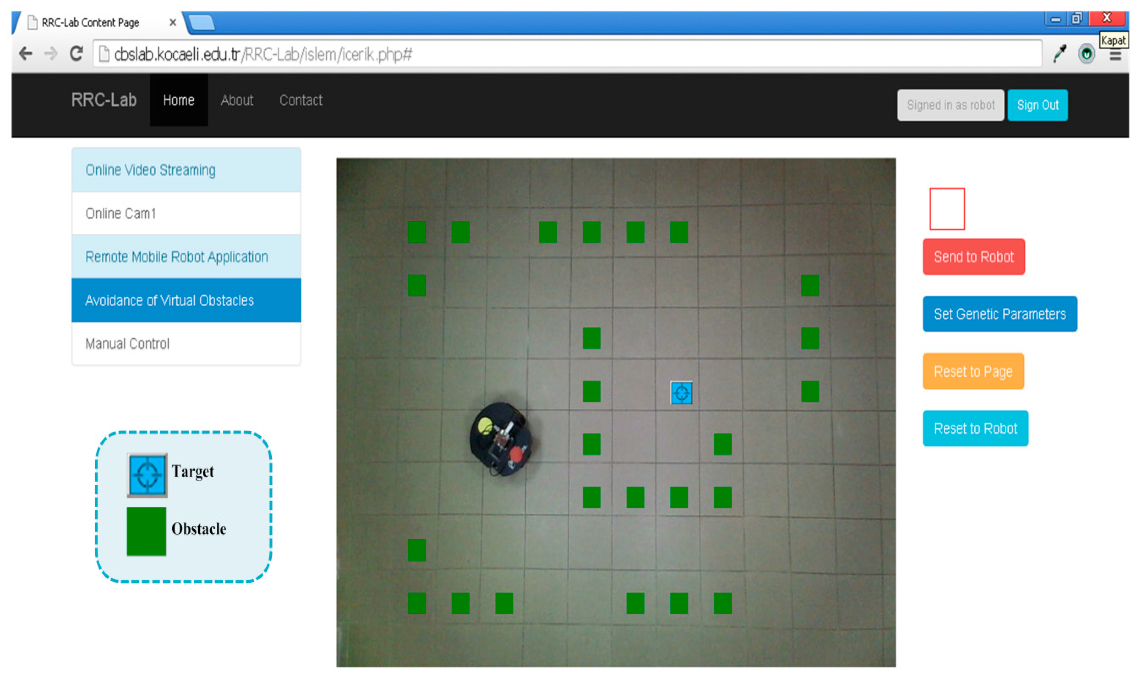
Figure 14.
The screen view of where the virtual obstacles and target are located.

Figure 15.
The final view of the motion planning experimental study.

Figure 16.
The screen view of the starting location of the mobile robot for manual control experimental study.
Figure 16.
The screen view of the starting location of the mobile robot for manual control experimental study.

Figure 17.
The screen view of the manual control experimental study after the mobile robot completes its navigation.
Figure 17.
The screen view of the manual control experimental study after the mobile robot completes its navigation.


Table 1.
The calculation of the rotate angles of the robot.
| Condition | Direction (B/F) | Robot Angle (θ) |
|---|---|---|
| F | ||
| B | ||
| B | ||
| F | ||
| F | ||
| F | ||
| B | ||
| F |
Table 2.
The RRC-Lab performance and usability survey and its results.
| No. | Statement | Mean ± SD | Range |
|---|---|---|---|
| 1 | I think that The RRC-Lab is easy to use. | 4.74 ± 0.45 | 3–5 |
| 2 | The RRC-Lab is useful to understand the mobile robot’s obstacle avoidance problem. | 3.79 ± 0.79 | 3–5 |
| 3 | The RRC-Lab is useful to enhancement your interest level for mobile robot navigation. | 3.68 ± 0.82 | 3–5 |
| 4 | The RRC-Lab is helpful to learn how to use genetic algorithm parameters. | 4.16 ± 0.76 | 3–5 |
| 5 | The RRC-Lab is useful to understand the relationship between genetic algorithm and mobile robot obstacle avoidance problem. | 4.26 ± 0.87 | 3–5 |
| 6 | I think that the various functions in the RRC-Lab are well integrated. (mobile robot, optimization techniques, virtual environment, Beagleboard, etc.) | 4.16 ± 0.69 | 3–5 |
| 7 | I think that technical knowledge is more useful when supported by RRC-Lab. | 4.58 ± 0.51 | 4–5 |
| 8 | I would like it integrated into the RRC-Lab project in similar optimization algorithms. | 4.53 ± 0.61 | 4–5 |
| 9 | It would be nice if I had systems like RRC-Lab for similar courses. | 4.37 ± 0.60 | 4–5 |
| 10 | I think that most students will learn to use RRC-Lab rapidly. | 4.47 ± 0.61 | 4–5 |
© 2020 by the authors. Licensee MDPI, Basel, Switzerland. This article is an open access article distributed under the terms and conditions of the Creative Commons Attribution (CC BY) license (http://creativecommons.org/licenses/by/4.0/).
Share and Cite
MDPI and ACS Style
Solak, S.; Yakut, Ö.; Dogru Bolat, E. Design and Implementation of Web-Based Virtual Mobile Robot Laboratory for Engineering Education. Symmetry 2020, 12, 906. https://doi.org/10.3390/sym12060906
AMA Style
Solak S, Yakut Ö, Dogru Bolat E. Design and Implementation of Web-Based Virtual Mobile Robot Laboratory for Engineering Education. Symmetry. 2020; 12(6):906. https://doi.org/10.3390/sym12060906
Chicago/Turabian StyleSolak, Serdar, Önder Yakut, and Emine Dogru Bolat. 2020. "Design and Implementation of Web-Based Virtual Mobile Robot Laboratory for Engineering Education" Symmetry 12, no. 6: 906. https://doi.org/10.3390/sym12060906
Note that from the first issue of 2016, this journal uses article numbers instead of page numbers. See further details here.