Heat Transfer of Oil/MWCNT Nanofluid Jet Injection Inside a Rectangular Microchannel
by
 ,
,
Esmaeil Jalali
1, 
Omid Ali Akbari
2,
M. M. Sarafraz
3 ,
,
Tehseen Abbas
4 and
Mohammad Reza Safaei
5,6,* 1
Department of Mechanical Engineering, Najafabad Branch, Islamic Azad University, Najafabad, Iran
2
Young Researchers and Elite Club, Khomeinishahr Branch, Islamic Azad University, Khomeinishahr, Iran
3
Centre for Energy Technology, School of Mechanical Engineering, The University of Adelaide, South Australia, Australia
4
Department of Mathematics, University of Education Lahore, Faisalabad Campus, Faisalabad, Pakistan
5
Division of Computational Physics, Institute for Computational Science, Ton Duc Thang University, Ho Chi Minh City, Vietnam
6
Faculty of Electrical and Electronics Engineering, Ton Duc Thang University, Ho Chi Minh City, Vietnam
*
Author to whom correspondence should be addressed.
Symmetry 2019, 11(6), 757; https://doi.org/10.3390/sym11060757
Submission received: 20 March 2019
/
Revised: 23 May 2019
/
Accepted: 27 May 2019
/
Published: 4 June 2019
(This article belongs to the Special Issue Symmetry and Fluid Mechanics)
Abstract
:In the current study, laminar heat transfer and direct fluid jet injection of oil/MWCNT nanofluid were numerically investigated with a finite volume method. Both slip and no-slip boundary conditions on solid walls were used. The objective of this study was to increase the cooling performance of heated walls inside a rectangular microchannel. Reynolds numbers ranged from 10 to 50; slip coefficients were 0.0, 0.04, and 0.08; and nanoparticle volume fractions were 0–4%. The results showed that using techniques for improving heat transfer, such as fluid jet injection with low temperature and adding nanoparticles to the base fluid, allowed for good results to be obtained. By increasing jet injection, areas with eliminated boundary layers along the fluid direction spread in the domain. Dispersing solid nanoparticles in the base fluid with higher volume fractions resulted in better temperature distribution and Nusselt number. By increasing the nanoparticle volume fraction, the temperature of the heated surface penetrated to the flow centerline and the fluid temperature increased. Jet injection with higher velocity, due to its higher fluid momentum, resulted in higher Nusselt number and affected lateral areas. Fluid velocity was higher in jet areas, which diminished the effect of the boundary layer.
1. Introduction
In recent years, industrial developments have led scientists to search for methods to improve heat transfer in heat exchangers and industrial equipment. Therefore, a new generation of cooling fluids, called nanofluids, is used in industrial and commercial applications. Cooling fluid jet is used in turbine blade cooling and indirect access surfaces. Metal and non-metal nanoparticles have a higher thermal conductivity coefficient than water and lead to higher conductive heat transfer coefficients of fluid, as well as improve the temperature distribution of the nanofluid. Experimental results show that adding nanoparticles to the base fluid increases the heat transfer coefficient of nanofluids. Using nanofluids is one of the novel heat transfer improvement methods with high efficiency [1,2,3,4]. Numerous researchers have investigated the thermal or hydrodynamic performance of nanofluids in different microchannel heat sinks [5,6,7]. Hang et al. [8] numerically investigated the heat transfer performance of a microchannel heat sink with different nanofluids. Akbari et al. [9] studied laminar flow and heat transfer parameters of water/Al2O3 nanofluid with different nanoparticle volume fractions inside a rectangular microchannel and found that using rough surfaces in microchannel leads to higher heat transfer. Behnampour et al. [10] numerically investigated laminar flow and heat transfer parameters of water/AgO nanofluid with different nanoparticle volume fractions in a rectangular microchannel and showed that by increasing fluid velocity, an optimized trade-off can be obtained between heat transfer, hydrodynamic behavior of nanofluid, and the performance evaluation criteria (PEC) variations. Geravandian et al. [11] numerically simulated the laminar heat transfer of nanofluid flow in a rectangular microchannel and revealed that by increasing TiO2 nanoparticles, heat transfer, friction coefficient, PEC, and pressure drop increase. Studies on the effect of using cooling fluid jet injection on heated surfaces [12] and other methods to increase heat transfer, such as using dimples, rough surfaces [13,14], and twisted tapes [15,16], have been conducted for different industrial and experimental geometries. These studies show that by creating vortexes, uniform temperature distribution can be obtained. Fluid jet plays an important role in cooling technologies and by creating better mixtures of cooling fluid flow, thermal performance can be enhanced [17,18,19]. Chen et al. [20] numerically and experimentally investigated the forced convection heat transfer inside a rectangular channel for determining fluid flow and heat transfer properties. They also compared the performance of heat sinks with solid and perforated pins and showed that by increasing the number of perforations and their diameter, pressure drop decreases and the Nusselt number increases. In their experiments, thermal performance of the heat sink with perforated pins was better than with solid pins. Nafon et al. [21] experimentally studied the effects of inlet temperature, Reynolds number, and heat flux on heat transfer properties of a water/TiO2 nanofluid jet in a semi-rectangular heat sink, and showed that the average heat transfer coefficient of nanofluid is higher than base fluid, and the pressure drop increases by increasing the nanoparticle volume fraction. Jasperson et al. [22] studied the thermal and hydrodynamic performance of a copper microchannel and a pin fin microchannel and showed that by increasing the volume rate of flow, the thermal resistance of a pin fin heat sink decreases. Zhuwang et al. [23] studied heat transfer inside a microchannel with fluid jet and different coolants and showed that using fluid jet results in higher heat transfer compared with ordinary parallel flows.
Few studies have investigated the thermal and hydrodynamic performance of laminar nanofluid flow in a rectangular microchannel with cooling fluid jet injection. Therefore, the main purpose of this study is to investigate heat transfer improvement methods, such as using nanofluid and direct fluid jet injection. We also investigated the effect of the hydrodynamic velocity boundary condition on the cooling performance of the microchannel. In the present numerical study, laminar flow and heat transfer of oil/MWCNT nanofluid inside a two-dimensional microchannel with nanofluid jet injection were simulated using a finite volume method. Cooling nanofluid jet injection in a microchannel disturbs the thermal boundary layer and increases the heat transfer rate. The use of fluid jet injection in various sections of the microchannel is one of the novelties of this study. Fluid flow and heat transfer behavior are separately simulated in cases with no jets and with one, two, and three jets. The effect of applying slip and no-slip boundary conditions on solid walls of microchannel on the flow and heat transfer were studied.
2. Problem Definition
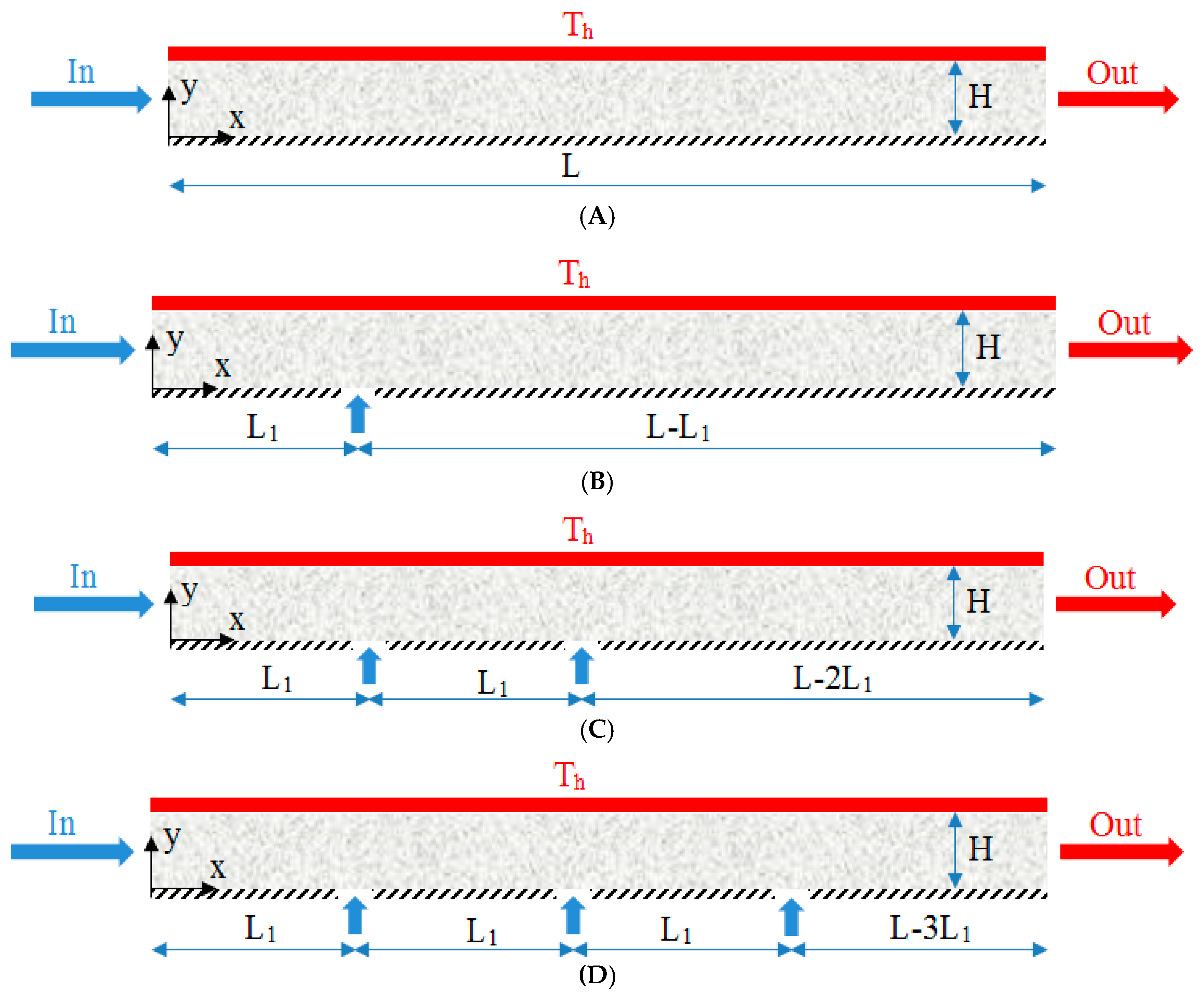
In the present numerical study, oil/MWCNT nanofluid flow was simulated in 0–4% nanoparticle volume fractions and Reynolds numbers of 10 and 50. We considered different numbers of fluid jets on the insulated bottom wall of the microchannel. The top heated wall of the microchannel had a constant temperature of Th = 303 K. The inlet cold fluid entered from the left side of the microchannel with the temperature of Tc = 293 K. Figure 1 shows the microchannel in the present study.
The length of studied microchannel was L = 2500 µm, the width of inlet jet entrance was 10 µm, the height of microchannel was H = 50 µm, and the jet pitch was L1 = 500 µm. The velocity of the inlet nanofluid jet at all studied Reynolds numbers was constant (Re = 10). Fluid flow and heat transfer inside the microchannel were separately simulated in cases with no jet and with 1, 2, and 3 jets. Nanofluids with high velocity through the lower wall were injected into the micro-channel. As the cooling fluid jet flowed on the surface, the temperature of this surface decreased. Also, in this investigation, the effect of applying slip and no-slip boundary conditions on solid walls of the microchannel in slip coefficients of B = 0.0, 0.04, and 0.08 were investigated. The flow was laminar, forced, Newtonian, single-phase, and incompressible; the nanofluid was homogeneous and uniform; and also, the radiation effects were neglected. The properties of the base fluid and nanofluid in different nanoparticle volume fractions are presented in Table 1 [24].
3. Governing Equations
Dimensionless Navier–Stokes equations for forced, laminar, steady, and single-phase nanofluid are presented for 2-D space, which are continuity, momentum, and energy equations [25]:
The dimensionless equations used this study are [26]:
For calculating local and average Nusselt number along the microchannel walls, the following equations are used:
The dimensionless boundary conditions are:
4. Numerical Details
Finite volume method [27,28] and the second-order upwind discretization method with maximum residual of 10−6 [29,30] was used. For coupling velocity–pressure equations, the SIMPLEC [31,32] algorithm was used. Also, the effect of nanoparticle volume fraction, Reynolds number, and jet number on flow and heat transfer parameters were investigated; and flow parameters, temperature, and streamlines contours are the presented.
The meshes in this study were rectangular and regular grids ranging from 25,000 to 100,000 grids were used for Reynolds numbers of 10 and 50, 2% volume fraction, and no-slip boundary conditions (Table 2). In order to ensure the independence of flow and heat transfer parameters from mesh number, Nusselt number and average velocity on flow centerline were studied for different mesh numbers. The 850 × 50 mesh number has better performance than 900 × 90, therefore, the former was used in the present simulations.
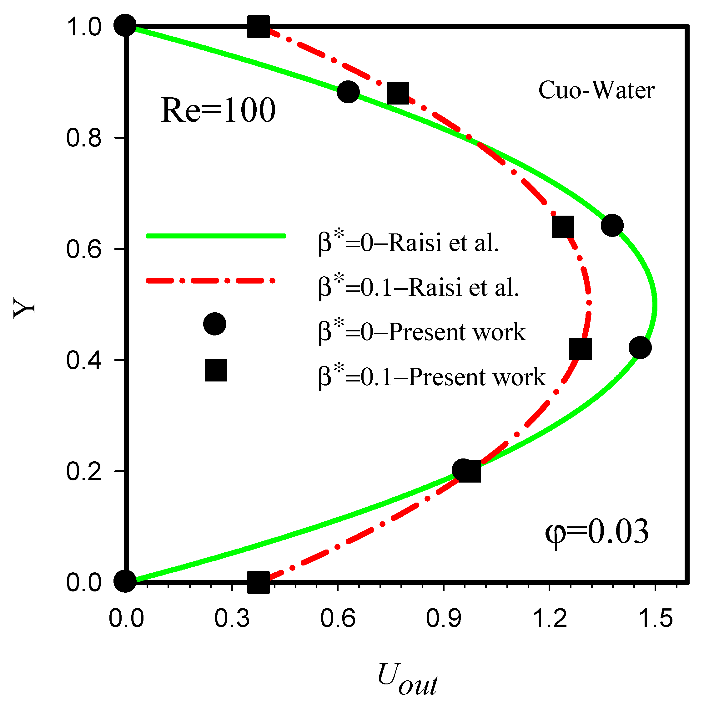
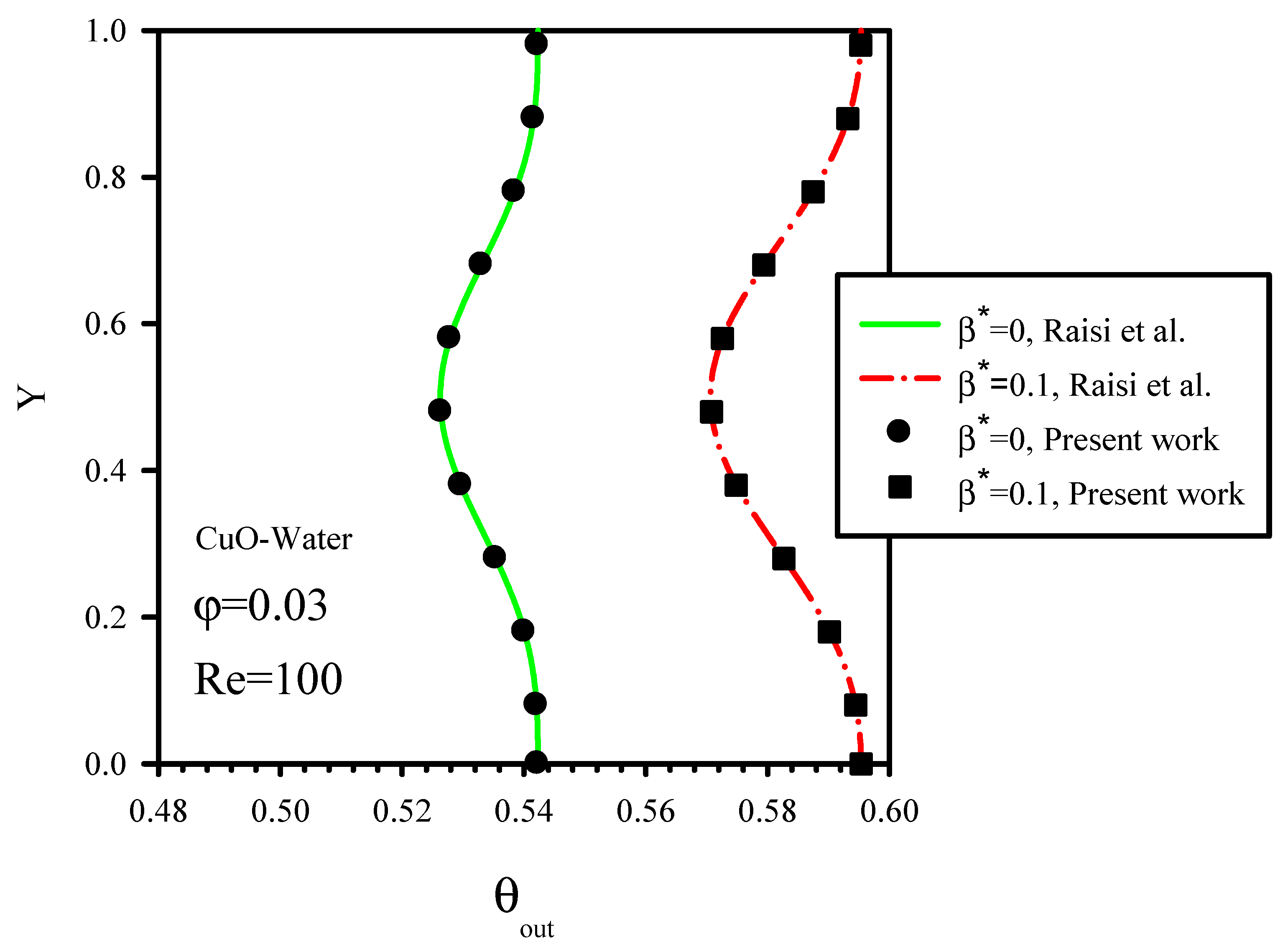
Figure 2 and Figure 3 show the validation of velocity and dimensionless flow temperature at the outlet section of microchannel against the results of Raisi et al. [33], who investigated laminar and forced flow of water/CuO nanofluid with different nanoparticle volume fractions in a two-dimensional rectangular microchannel using a finite volume method. The results of Raisi et al. [33] for 3% nanoparticle volume fraction, Re = 100, and different slip velocity coefficients were used for the validation. There is good agreement between the results of the present study and Raisi et al. [33]. Therefore, the boundary conditions and assumptions of this study are correct.
5. Results and Discussion
In the present numerical study, the effect of nanofluid jet injection on laminar flow and heat transfer of oil/MWCNT nanofluid for 0–4% nanoparticle volume fractions, at Reynolds numbers of 10 and 50, and different slip velocity coefficients was numerically studied. The effects of the variations of jet number, nanoparticle volume fractions, and velocity boundary layer on solid walls of microchannel were also studied. Reynolds number, nanoparticle volume fraction, and slip velocity coefficient were input variables and their effect on Nusselt number, temperature domain, velocity domain, flow parameters, and temperature contours were investigated and compared based on their local and average values.
5.1. Streamlines and Isothermal Contours
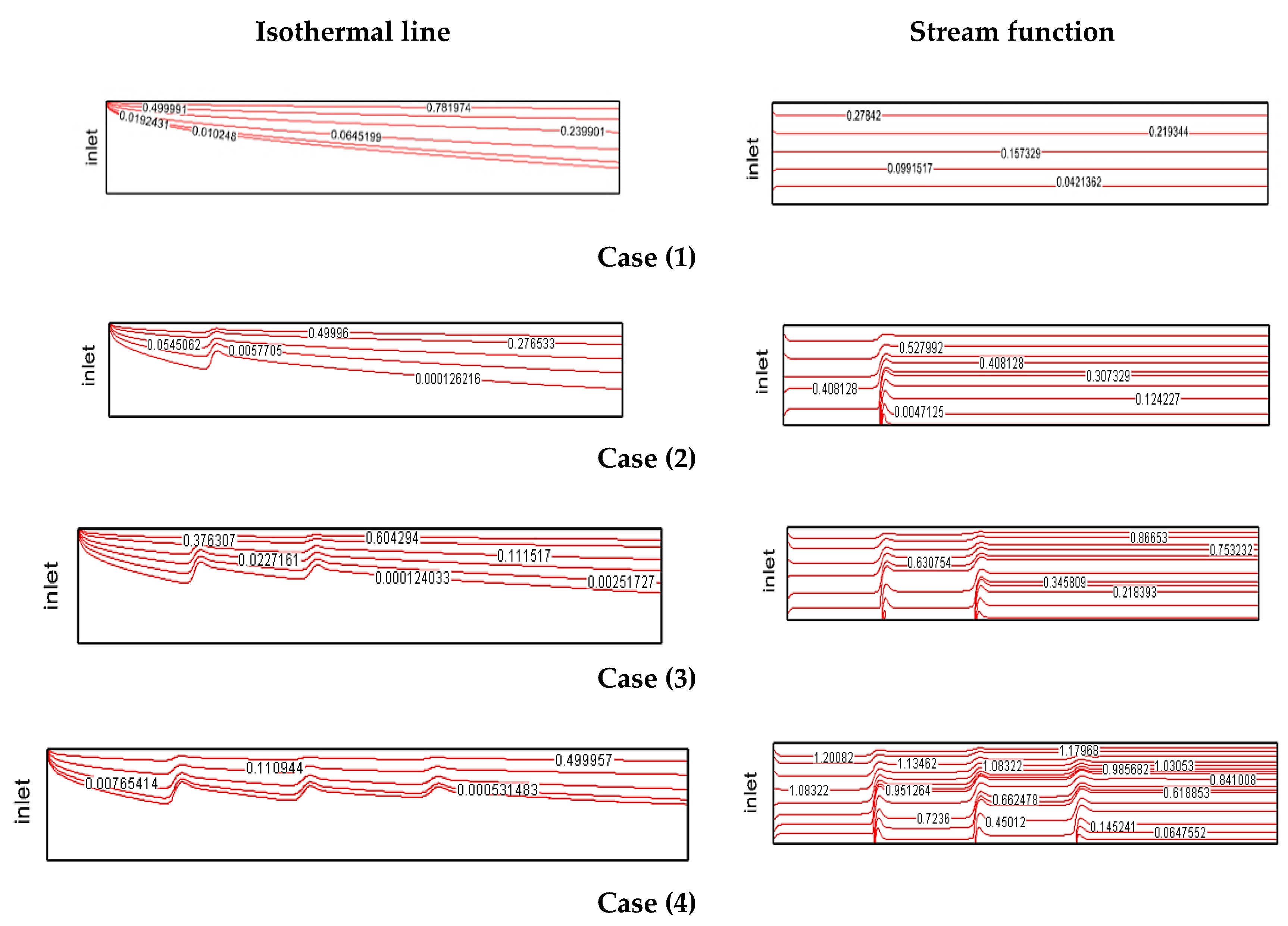
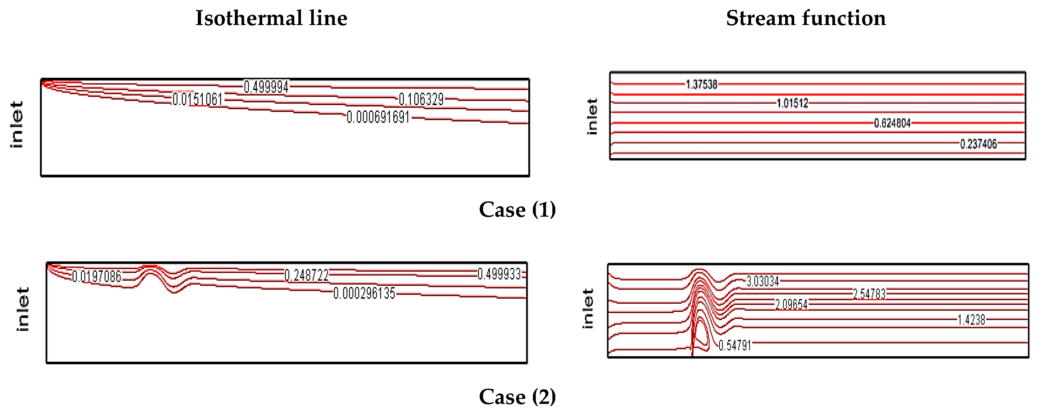
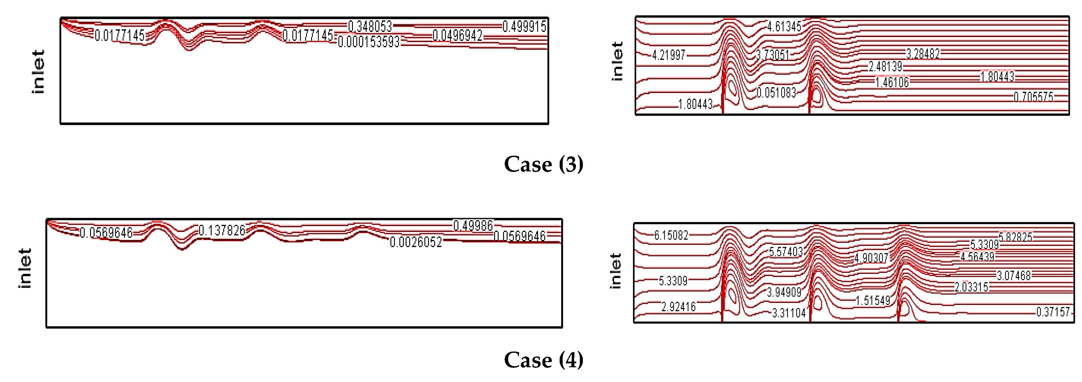
In Figure 4, streamline contours (right side) and constant temperature contours (left side) are shown for Re = 10, B = 0.04, and φ = 2% for cases 1, 2, 3, and 4. In these contours, the effect of fluid motion with minimum velocity along the microchannel at different nanofluid jet injection on the heated surface was investigated. The temperature difference between inlet cold fluid and the heated wall improves heat transfer and creates temperature gradients. Fluid motion and its impact with the solid walls of the microchannel creates velocity gradients in areas close to the wall. In general, fluid motion along the microchannel leads to the creation of velocity and thermal boundary layers. Nanofluid jet injection on fluid direction results in the elimination of velocity and thermal boundary layers. In all contours, by increasing the number of fluid jets, areas with eliminated boundary layers become larger. Areas with a high number of jet injections have smaller velocity boundary layers. In the cases with more jets, due to the high volume of crossing fluid, axial velocity parameters of fluid are higher than the cases with fewer jets.
Streamline contours (right side) and constant temperature contours (left side) at Re = 50, B = 0.04, and φ = 2% are presented in Figure 5. The effect of increasing jet number on the heated surface on these contours is shown for cases 1, 2, 3, and 4. In the inlet areas of the microchannel and jet injection areas is 5 times higher, contrary to Figure 4. Increasing fluid velocity decreases the thermal boundary layer thickness. Increasing the fluid momentum results in higher crossing fluid velocity. At Re = 50, by increasing the number of fluid jets, due to the better mixture of fluid and reduction of temperature curve slope, a significant reduction of the thermal boundary layer thickness is observed. According to the streamline contours, nanofluid jet injection with higher velocity results in better mixture of flow and creation of local vortices. By increasing Reynolds number, especially in the last jet, the effect of vertical jet injection decreases due to the higher of volumetric rate of crossing fluid and creation of a smaller vortex behind each jet.
5.2. Local Nusselt Number
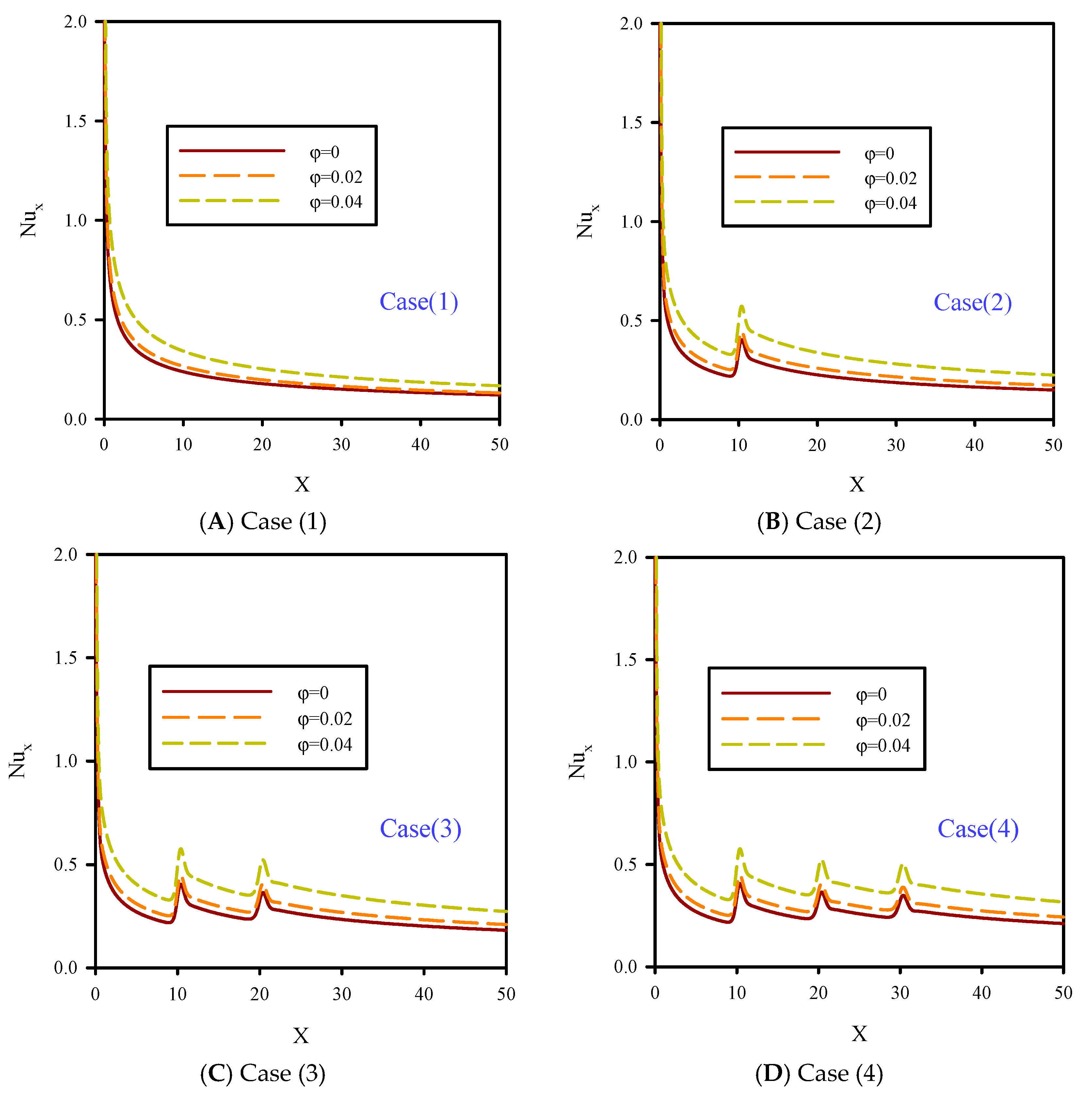
In Figure 6, the local Nusselt number on the heated wall of the microchannel is shown for Re = 10, B = 0.04, and different nanoparticles volume fractions. In this figure, we have different jet numbers with minimum fluid velocity. Nanoparticle volume fractions were 0–4%. Heat transfer occurs because of temperature differences between fluid and the top heated wall. The value of heat transfer has a direct relationship with Nusselt number and temperature line slope. Uniform temperature distribution and removal of temperature gradients are desirable and lead to higher Nusselt numbers. The local jump in the Nusselt number in Figure 6 was because of the low temperature of the injected fluid jet on the heated surface. In these areas, the heat transfer distribution was more uniform and the Nusselt number increased. In all curves for Figure 6, by adding nanoparticle volume fraction, the Nusselt number and heat transfer were significantly increased.
In Figure 7, the local Nusselt numbers at Re = 50, B = 0.04, and different nanoparticle volume fractions are shown. In this figure, the effect of the increasing fluid velocity on Nusselt number is compared with Figure 6. Increasing ϕ and the number of jets resulted in the higher Nusselt number graphs in Figure 7. Figure 6 and Figure 7 show the elimination of thermal and velocity boundary layers due to the fluid jet injection, which is more significant at higher Reynolds numbers. Jet injection with higher velocity leads to the increase of the Nusselt number due to the higher fluid momentum which affects the lateral regions. Increasing the nanoparticle volume fraction at Re = 50, compared to Re = 10, resulted in a significant rise of the Nusselt number. In general, the local Nusselt number on heated walls showed that using fluid jet injection with low temperature can increase the heat transfer rate. Compared to the primary jets, the heat transfer performance of the last jets was low, because by adding more jets, the effects of fluid momentum and crossing fluid become more significant, which diminishes the lateral flow by vertical jets as they need higher momentum. Therefore, in cases 2 and 3, the lateral cooling areas were narrower.
5.3. Temperature along the Symmetry Plane
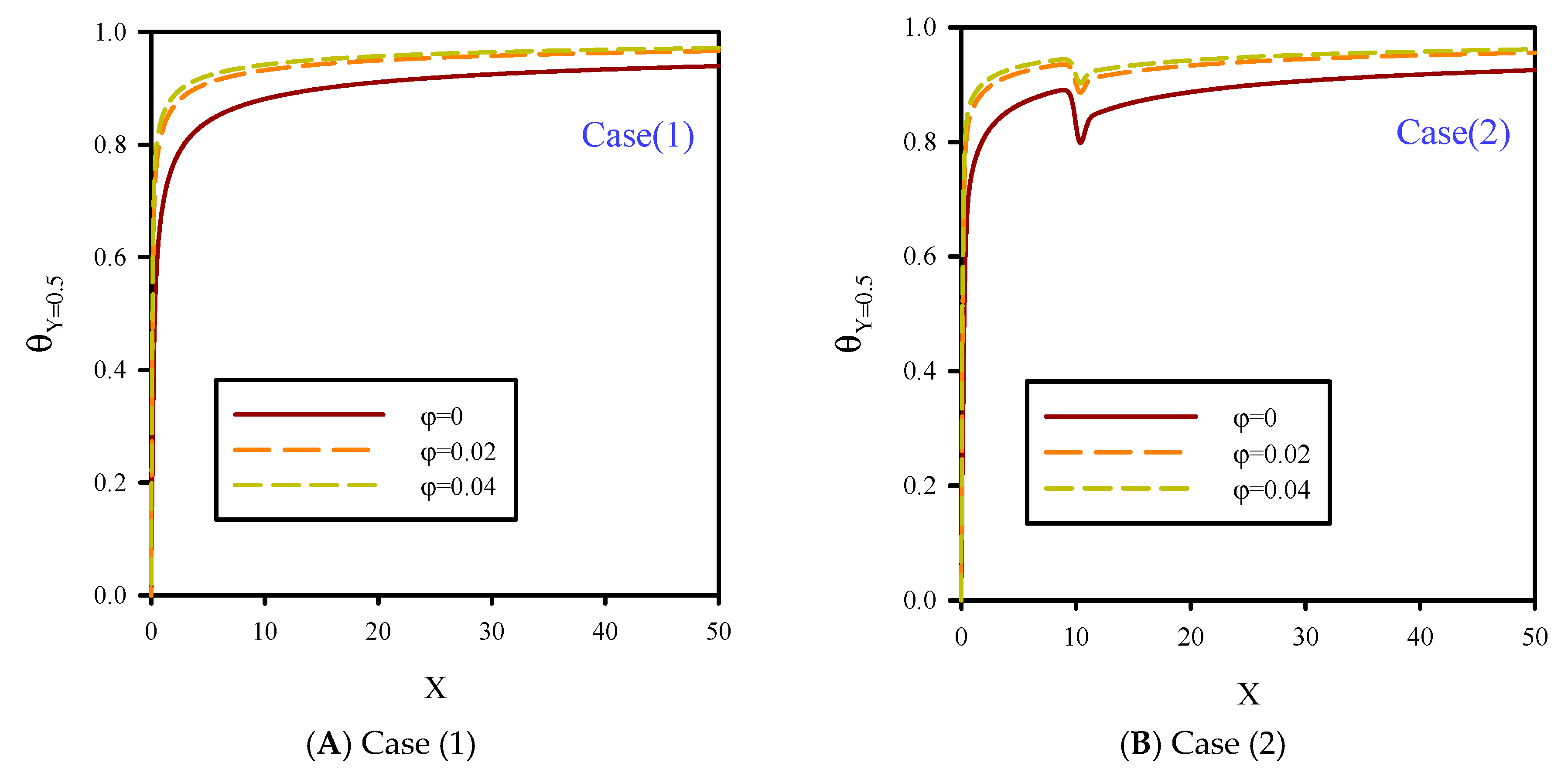
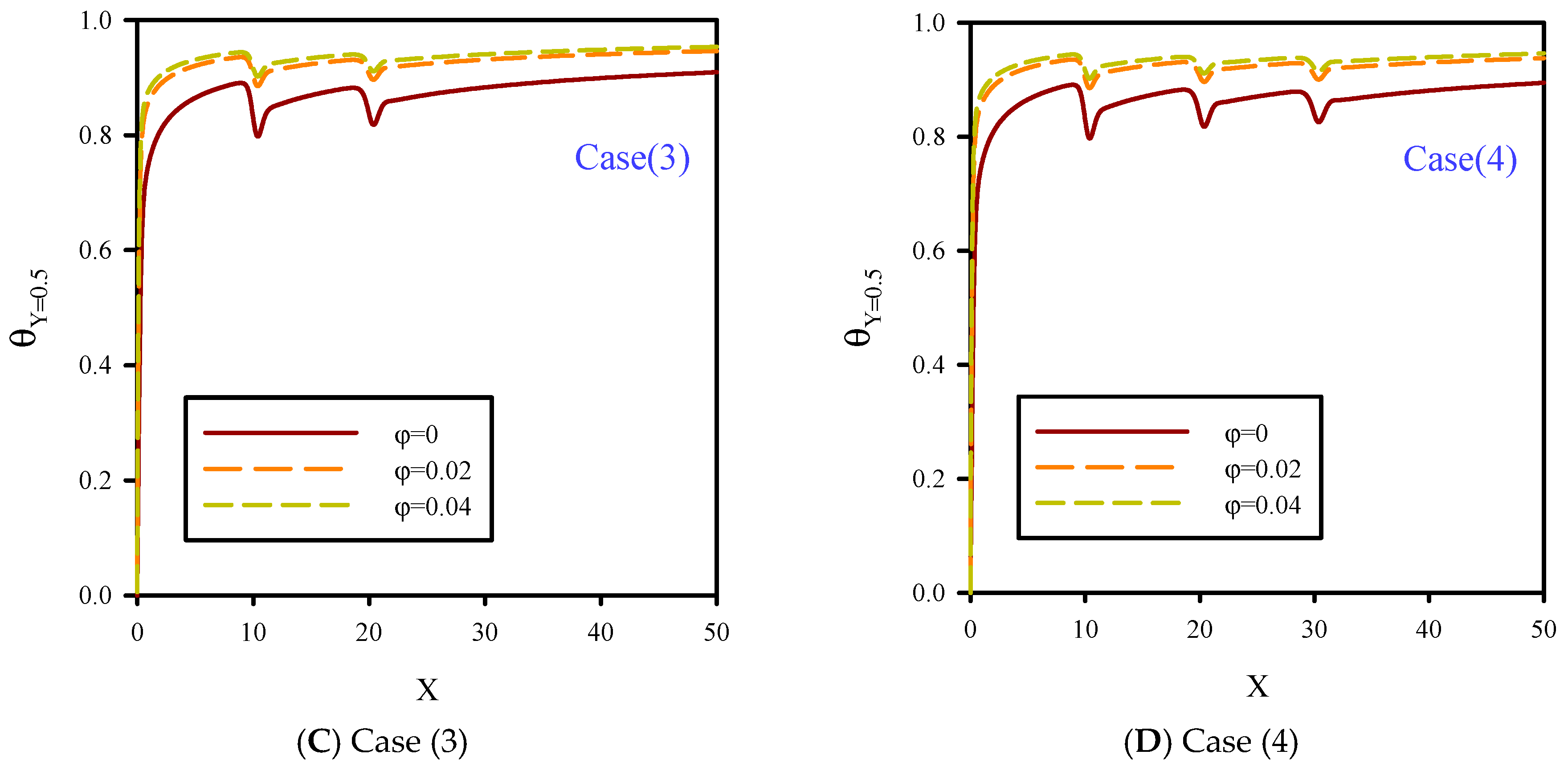
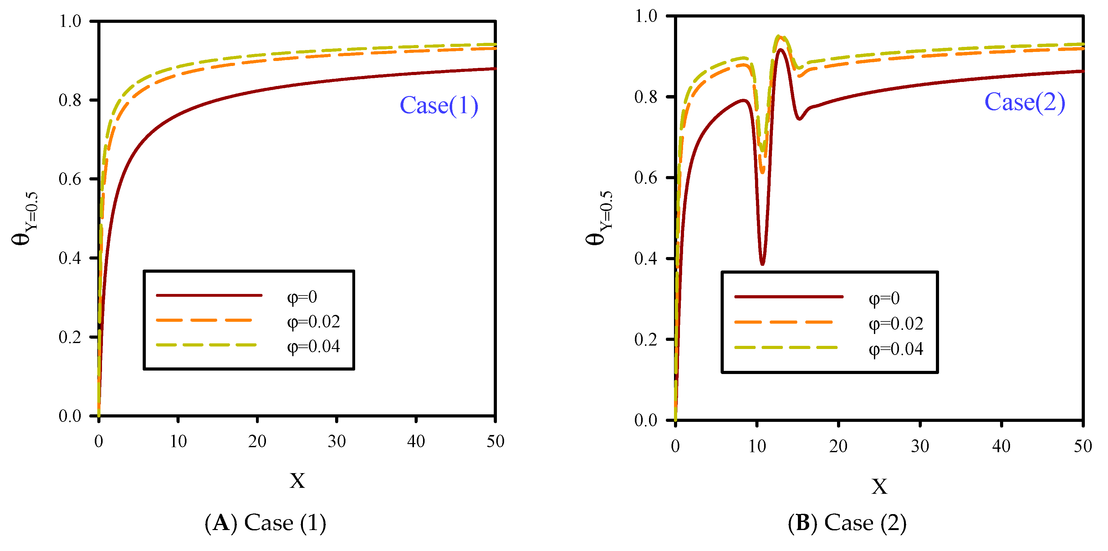
In Figure 8, local dimensionless temperature distribution on flow centerline for Re = 10, B = 0.04, and volume fractions of 0–4% is presented. The dimensionless temperature distribution in the central section of the microchannel was influenced by the reduction of fluid velocity and jet number for cases 1, 2, 3, and 4, and different nanoparticle volume fractions. Because of the temperature difference between the fluid and heated surface, the penetration of the thermal boundary layer affected all areas of the microchannel, especially the areas in the central line of flow. Figure 8 shows that increasing ϕ resulted in higher thermal conductivity of the microchannel and uniform temperature distribution in all areas of the microchannel, especially in the heated areas. Due to the higher thermal conductivity of cooling fluid in higher nanoparticle volume fractions, temperature gradients in heated areas were diminished, and also, the conductivity of the fluid layers was higher. Therefore, by increasing ϕ, heat transfer penetrated the flow centerline, and because of the higher conductivity of the fluid layers, the fluid temperature rose.
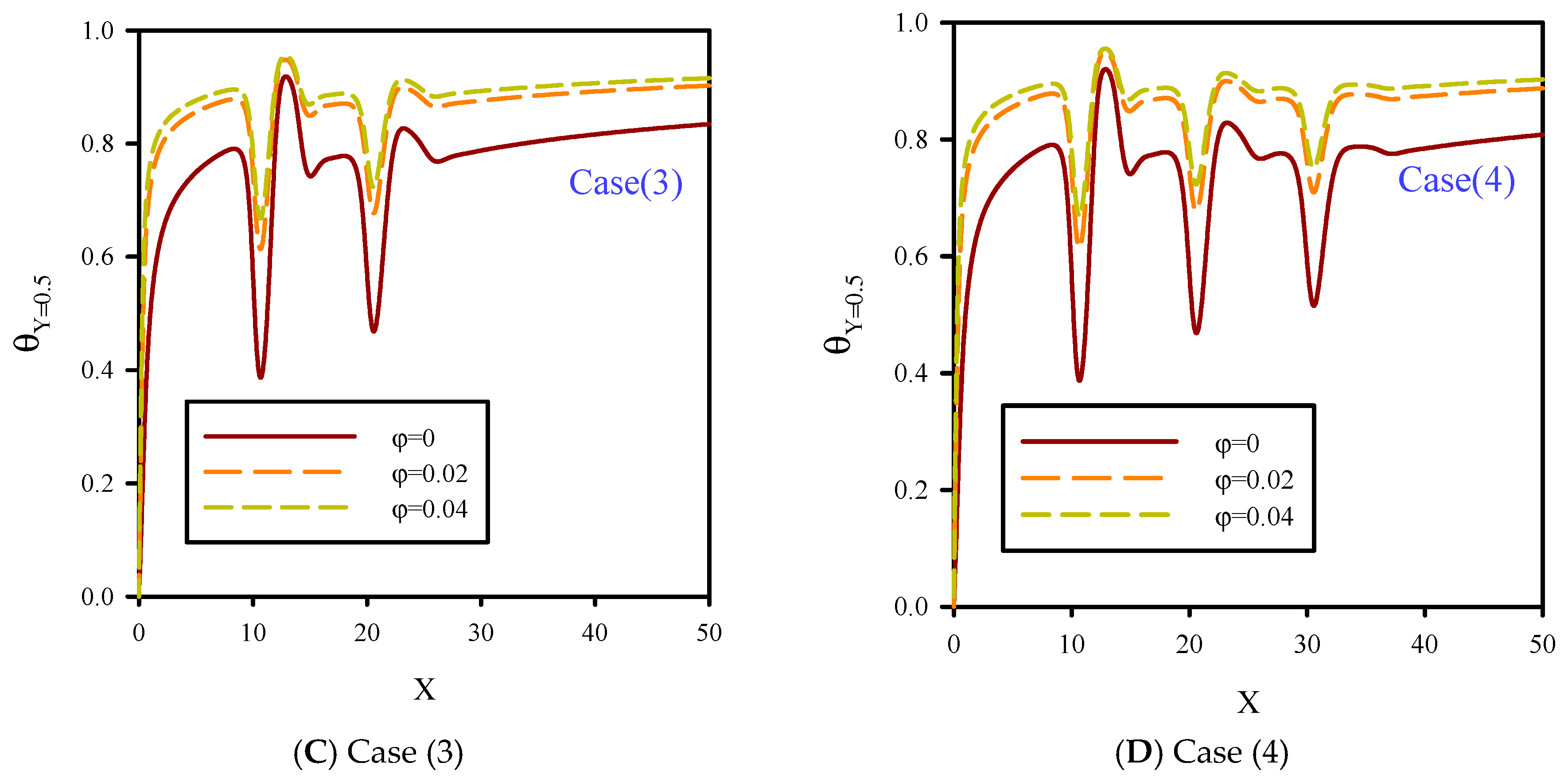
In Figure 9, local dimensionless temperature distribution at Re = 50, B = 0.04, and 0–4% nanoparticle volume fractions along the flow centerline are shown for cases 1, 2, 3, and 4. Increasing the number of jets resulted in lower temperature of the fluid, and thus the dimensionless temperature graphs in the microchannel centerlines were decreased, which was due to the reduction of temperature associated with increased fluid velocity and transferred temperature to the flow centerline. By increasing the velocity of injected cold fluid jet, the cold and hot fluids were better mixed. Consequently, the fluid temperature decreased significantly. According to Figure 8 and Figure 9, by decreasing the fluid velocity, the fluid becomes thermally better developed, which is due to the penetration of heat to the inlet section of the microchannel. By increasing the fluid velocity, the undeveloped length of flow at the inlet section of microchannel increases.
5.4. Axial Velocity along the Symmetric Plate
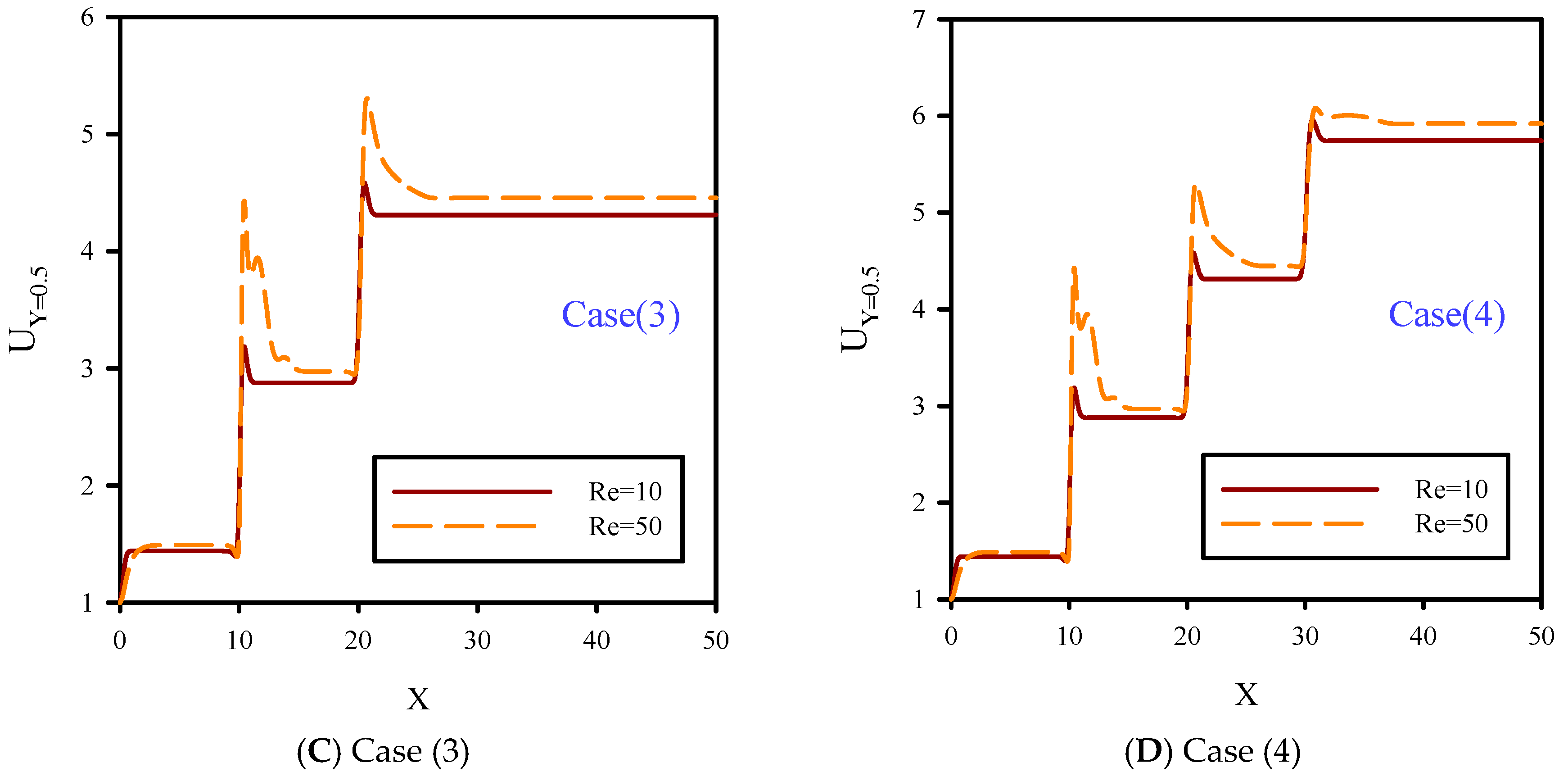
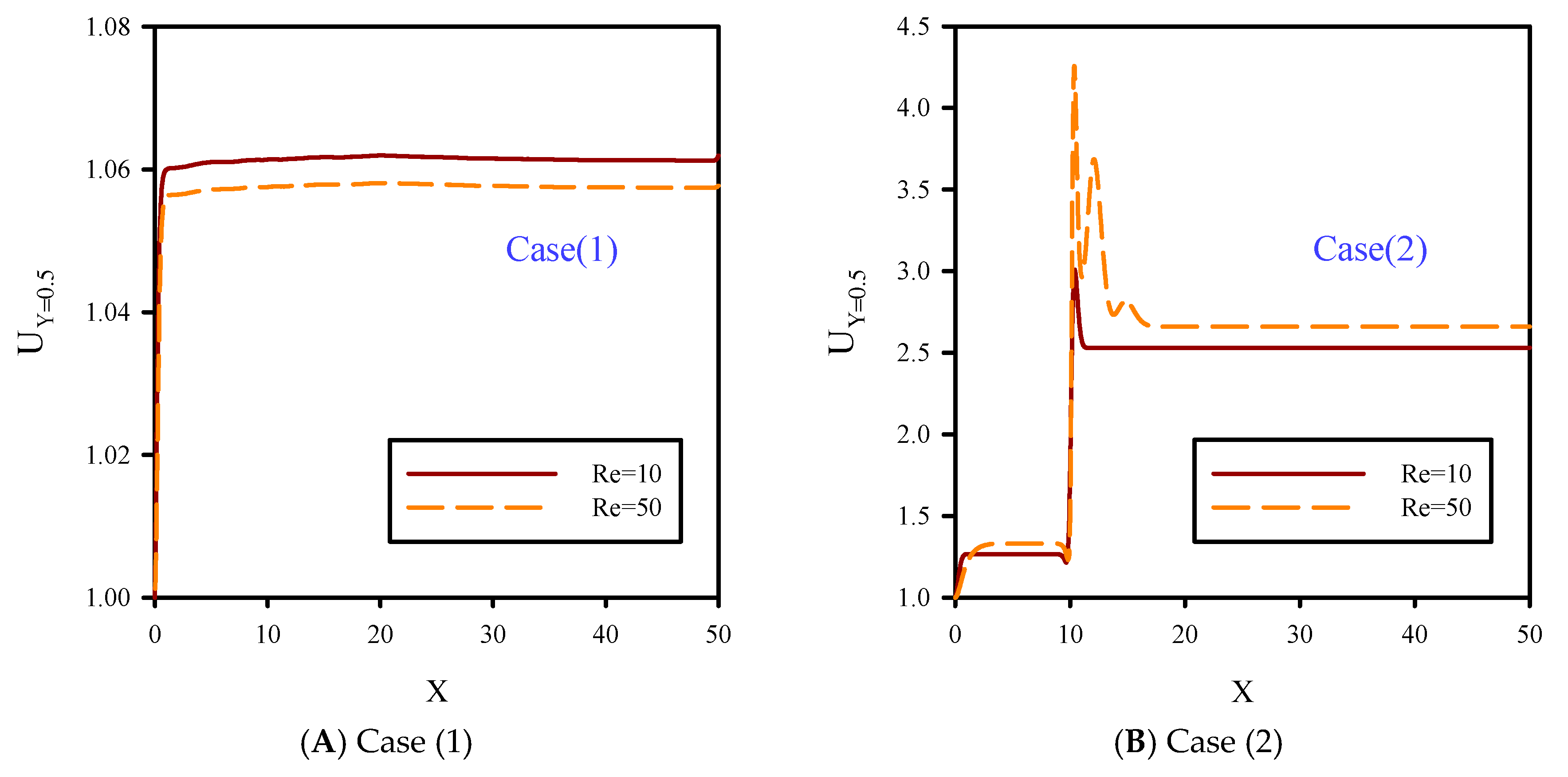
In Figure 10, dimensionless axial velocity in the flow centerline at Reynolds numbers of 10 and 50, B = 0.0, and φ=2% were investigated. Fluid motion along the microchannel was affected by velocity boundary layer caused by the solid walls. Contrary to the inlet velocity, fluid velocity was higher in case 1, which was due to the effects of the velocity boundary layer along the microchannel walls. In case 1, fluid velocity in developed areas at Re = 50 was lower than Re = 10. Fluid jet increased the volume rate of the crossing fluid downstream of the jets compared to areas upstream of the jets. Therefore, in cases 1, 2, and 3, fluid velocity increased in areas after the jets. In fact, high fluid velocity decreased the size of the velocity boundary layer. The velocity curves for fluid with Re = 50 were higher than fluid with Re = 10. In general, fluid jet eliminates the velocity boundary layer and prevents local flow development.
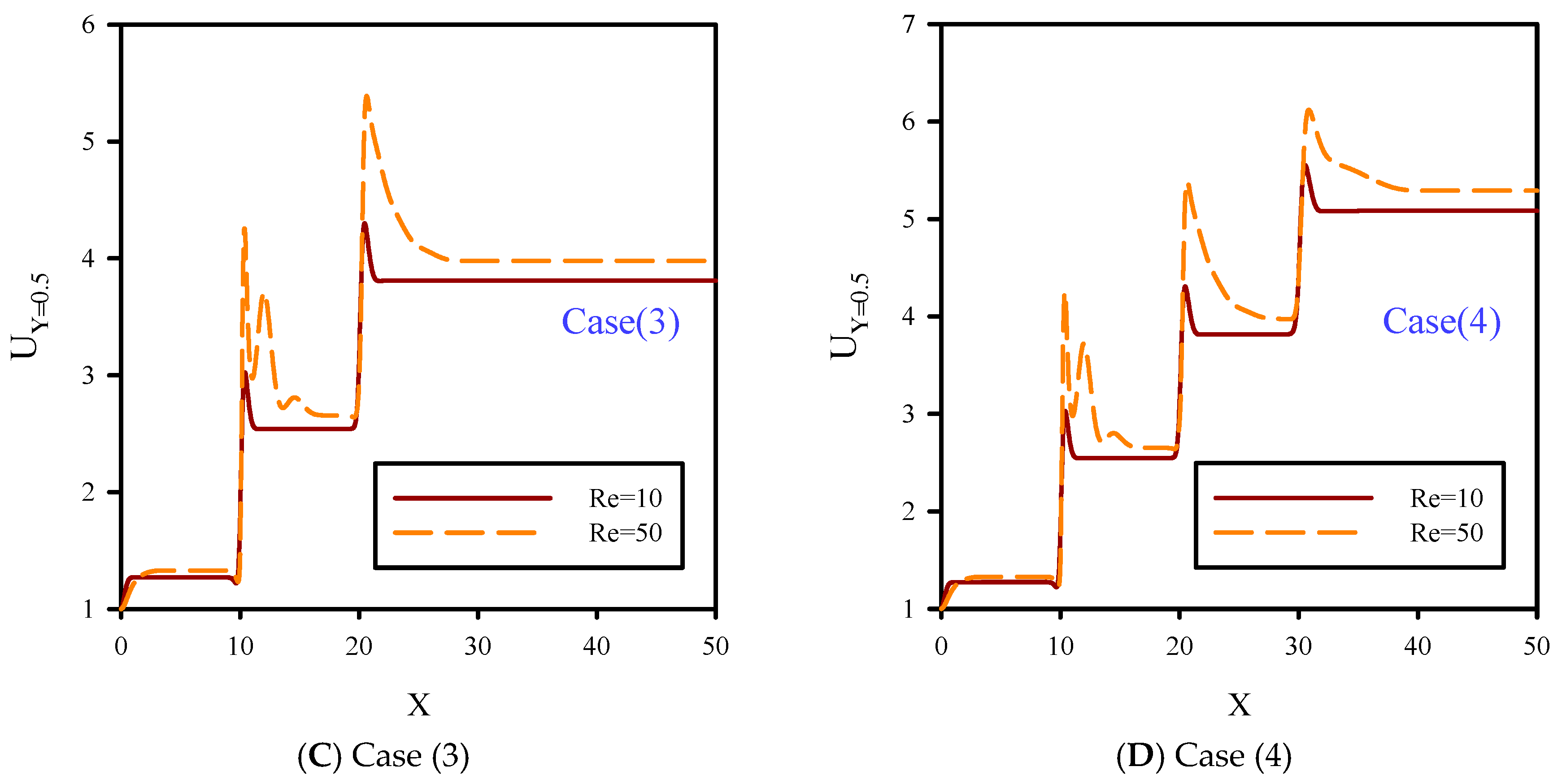
In Figure 11, dimensionless axial velocity along the flow centerline at Reynolds numbers of 10 and 50, B = 0.08, and φ = 2% are shown. Unlike Figure 10, the slip boundary condition was applied to the solid walls which facilitated fluid motion and reduced the velocity boundary layer on the solid walls of the microchannel. Therefore, the velocity profile in the flow centerline for all cases of 1, 2, 3, and 4 were lower than Figure 10. According to Figure 10 and Figure 11, increasing the slip velocity coefficient on the solid walls of the microchannel at Re = 10 had less effect than Re = 50. At Re = 50, the lateral mixture of flow covered more areas in the case with slip boundary conditions (BCs) compared with the no-slip BC case. According to Figure 11, this factor resulted in the microchannel contraction which increased the effect of jet injection areas and local axial velocity.
5.5. Average Nusselt Number on the Heated Surface
In Figure 12, the average Nusselt number at Reynolds numbers of 10 and 50, volume fractions of 0, 2, and 4%, and B = 0.04 are shown. Using fluid jet injection with low temperature and adding solid nanoparticles to the base fluid, heat transfer was improved. Increasing the number of jets resulted in a better mixture of cold and hot flows in the microchannel, reduction of total temperature of the microchannel, and better cooling performance of the nanofluid. Adding solid nanoparticles to the base fluid with higher volume fractions resulted in better temperature distribution, and the Nusselt number increased as well. Also, increasing the Reynolds number resulted in higher fluid velocity and better temperature distribution, especially in heated areas, and also, the average Nusselt number increased. Among investigated cases, case 4 had the highest value of Nusselt number due to the maximum number of cold fluid jet injection. In case 1, due to the lack of nanofluid jet injection, the effects of thermal and velocity boundary layers became significant, and this case had the lowest heat transfer and Nusselt number.
5.6. Effect of Slip Coefficient on Axial Velocity
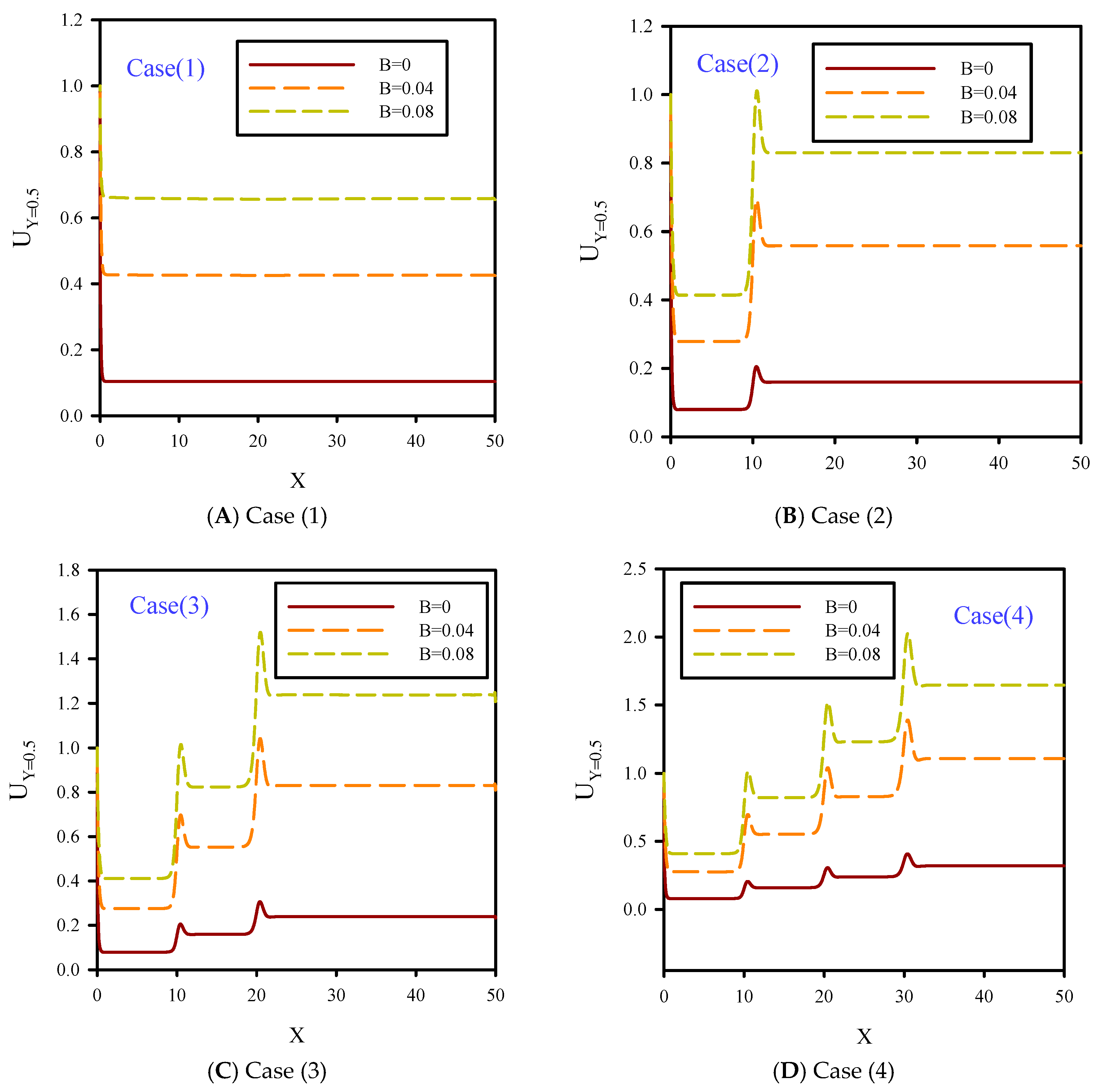
Dimensionless axial velocity in the central line of the microchannel at Re = φ = 2% and different slip coefficients was demonstrated in Figure 13. As it is seen, nanofluid jet injection at Re = 10 leads to some changes in jet areas. At this Reynolds number, increasing slip velocity coefficient results in lower fluid momentum dissipation and higher axial velocity. By increasing the slip velocity coefficient, because of the smaller velocity boundary layer, fluid moves on the microchannel walls with less friction. By increasing the jet number with a higher fluid velocity and volumetric rate of crossing fluid, the heat transfer was increased.
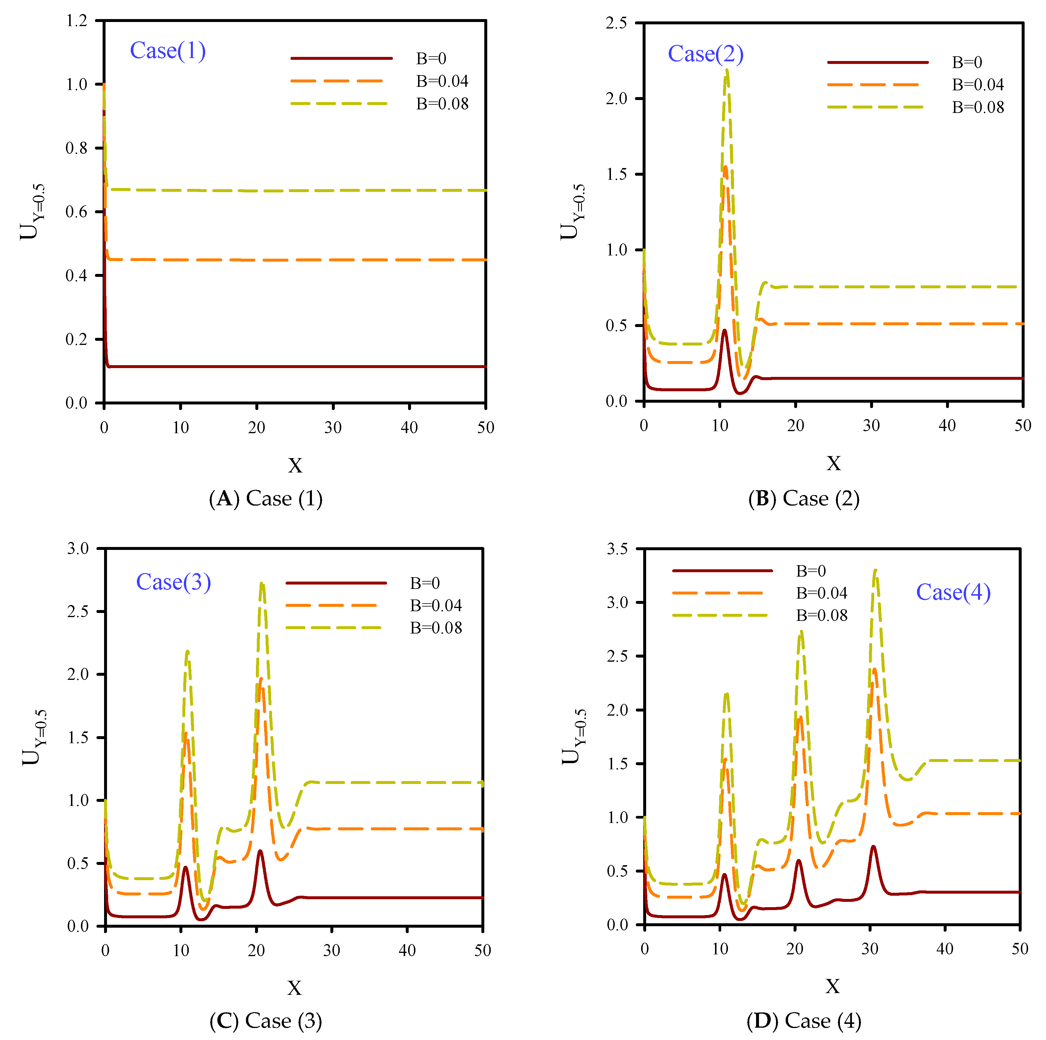
In Figure 14, dimensionless axial velocity in the flow centerline at Re = 50 and φ = 2% for cases 1, 2, 3, and 4 are shown. Increasing the slip coefficient on the solid surfaces parallel with the fluid direction, especially at higher Reynolds numbers, leads to the higher of fluid momentum. By increasing the slip velocity coefficient, due to the local flow contraction and significant changes in axial fluid velocity, fluid jet injection creates larger areas in the longitudinal direction. In Figure 14, because of the higher value of Reynolds number, the level of graphs are higher than those in Figure 13.
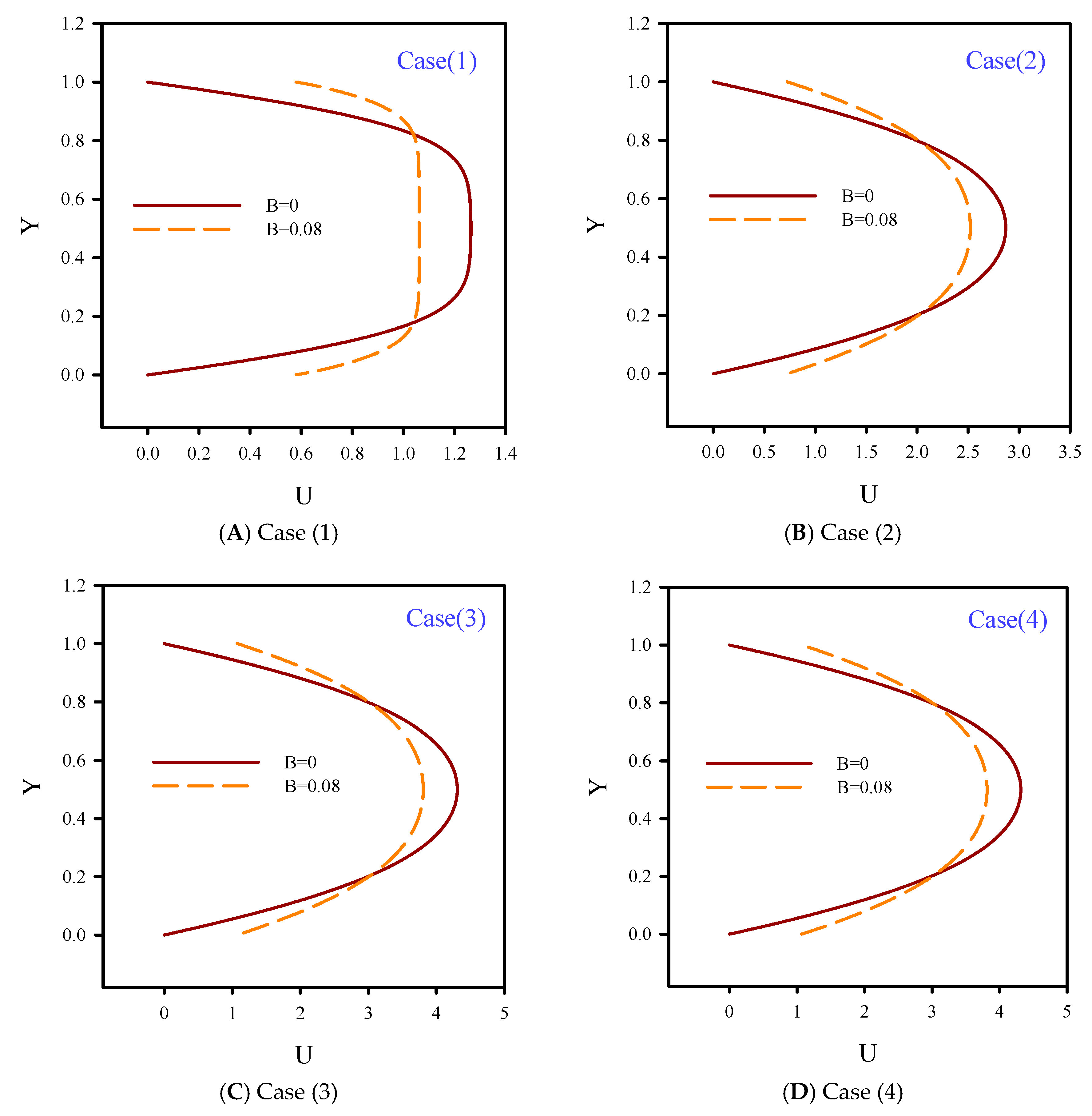
In Figure 15, dimensionless axial velocity profiles at the outlet section of the microchannel at Re = 10, φ = 4%, and slip coefficients of 0.0 and 0.08 are shown. Applying the slip coefficient on the solid walls resulted in a slight reduction of the axial velocity. By increasing the slip velocity coefficient, the velocity increased and the size of the velocity boundary layer on the heated surface decreased. According to the axial velocity profiles with the no-slip boundary condition, the effects of the velocity boundary layer was significant for the layers further away from the solid walls, and the velocity profile was stronger in the flow centerline. Therefore, from solid walls to flow centerline, the slope of the axial velocity variations was higher than the velocity profile with B = 0.08. Applying the slip velocity coefficient on the solid walls resulted in lower axial velocity gradients. The slope of the velocity curve from the walls to the flow centerline indicated lower gradients than the case with the no-slip boundary condition. The velocity profile in the central areas of the flow confirmed this issue and the corresponding curve had a milder slope.
6. Conclusions
In the present numerical study, laminar flow of oil/MWCNT nanofluid inside a two-dimensional microchannel with nanofluid jet injection was investigated. This simulation was carried out in a two-dimensional domain for laminar and Newtonian flow and heat transfer of oil/MWCNT nanofluid, with volume fractions of 0–4%, at Reynolds numbers of 10 and 50. Various jet numbers were used on the insulated bottom wall of the microchannel. Results showed that nanofluid jet injection with higher velocity leads to better flow mixture through the formation of local vortexes. In Re = 50, by increasing the number of fluid jets, the thermal boundary layer thickness becomes smaller because of the better mixture of fluid. Also, the temperature line slope was milder. Heat transfer occurs due to the temperature difference between fluid and the top heated wall. Heat transfer had a direct relationship with Nusselt number and the slope of the temperature line. Fluid jets eliminated the thermal and velocity boundary layers, which was more significant in higher Reynolds numbers. Because of the temperature differences between fluid and heated surfaces, penetration of the thermal boundary layer affected all sections of the microchannel, especially areas on the flow centerline. Because of higher conductivity of the fluid layer, by increasing the nanoparticle volume fraction, the heat transfer reached the flow centerline and the fluid temperature increased in that area. By decreasing fluid velocity, due to the higher temperature penetration, the developed length of flow became shorter and the fluid developed faster. Higher fluid velocity in areas with jets eliminated the velocity boundary layer.
Unlike the case with the no-slip boundary condition, by applying the slip coefficient on the solid walls of the microchannel, the lateral mixture of flow at Re = 50 covered larger areas. Increasing the Reynolds number resulted in higher fluid velocity and better temperature distribution, especially in heated areas, and this led to higher average Nusselt number. In fluid with higher velocity, applying the slip boundary condition on solid walls significantly increases the crossing fluid momentum.
Author Contributions
All authors contributed equally.
Funding
This research received no external funding.
Conflicts of Interest
The authors declare no conflict of interest.
Nomenclature
| B | dimensionless slip velocity coefficient |
| Cp | heat capacity, J kg−1 K−1 |
| d | diameter, m |
| H, L | microchannel height and length, m |
| k | thermal conductivity coefficient, Wm−1 K−1 |
| Nu | Nusselt number |
| P | fluid pressure, Pa |
| Pr = νf/f | Prandtl number |
| Re = ρf uc H /µf | Reynolds number |
| T | temperature, K |
| u, v | velocity components in the x-, y-directions, ms−1 |
| uc | inlet flow velocity, ms−1 |
| (U, V) = (u/U0, v/U0) | dimensionless flow velocity in the x-, y-direction |
| x, y | Cartesian coordinates, m |
| (X, Y = x/H, y/H) | dimensionless coordinates |
| Greek symbols | |
| α | thermal diffusivity, m2s−1 |
| β * | dimensionless slip velocity coefficient |
| φ | nanoparticle volume fraction |
| µ | dynamic viscosity, Pa s |
| θ = (T − TC)/(TH − TC) | dimensionless temperature |
| ρ | density, kg m−3 |
| ν | kinematics viscosity m2s−1 |
| Super- and Subscripts | |
| c | Cold |
| eff | Effective |
| f | base fluid (pure water) |
| h | Hot |
| m | Mean |
| nf | Nanofluid |
| s | solid nanoparticles |
References
- Gorla, R.S.R.; Chamkha, A. Natural convective boundary layer flow over a vertical plate embedded in a porous medium saturated with a non-Newtonian nanofluid. Int. J. Microscale Nanoscale Therm. Fluid Transp. Phenom. 2011, 3, 1–20. [Google Scholar]
- Dogonchi, A.S.; Chamkha, A.J.; Seyyedi, S.M.; Ganji, D.D. Radiative nanofluid flow and heat transfer between parallel disks with penetrable and stretchable walls considering Cattaneo–Christov heat flux model. Heat Transf. Asian Res. 2018, 47, 735–753. [Google Scholar] [CrossRef]
- Goshayeshi, H.R.; Safaei, M.R.; Goodarzi, M.; Dahari, M. Particle Size and Type Effects on Heat Transfer Enhancement of Ferro-nanofluids in a Pulsating Heat Pipe under Magnetic Field. Powder Technol. 2016, 301, 1218–1226. [Google Scholar] [CrossRef]
- Khanafer, K.; Vafai, K. A critical synthesis of thermophysical characteristics of nanofluids. Int. J. Heat Mass Transf. 2012, 54, 4410–4428. [Google Scholar] [CrossRef]
- Kosar, A.; Peles, Y. TCPT-2006-096. R2: Micro Scale Pin Fin Heat Sinks—Parametric Performance Evaluation Study. IEEE Trans. Compon. Packag. Technol. 2007, 30, 855–865. [Google Scholar] [CrossRef]
- Sivasankaran, H.; Asirvatham, G.; Bose, J.; Albert, B. Experimental Analysis of Parallel Plate and Crosscut Pin Fin Heat Sinks for Electronic Cooling Applications. Therm. Sci. 2010, 14, 147–156. [Google Scholar] [CrossRef]
- Mital, M. Analytical Analysis of Heat Transfer and Pumping Power of Laminar Nanofluid Developing Flow in Microchannels. Appl. Therm. Eng. 2012, 50, 429–436. [Google Scholar] [CrossRef]
- Hung, T.C.; Yan, W.M.; Wang, X.D.; Chang, C.Y. Heat Transfer Enhancement in Microchannel Heat Sinks using Nanofluids. Int. J. Heat Mass Transf. 2012, 55, 2559–2570. [Google Scholar] [CrossRef]
- Akbari, O.A.; Toghraie, D.; Karimipour, A. Impact of ribs on flow parameters and laminar heat transfer of water–aluminum oxide nanofluid with different nanoparticle volume fractions in a three-dimensional rectangular microchannel. Adv. Mech. Eng. 2015, 7, 1–11. [Google Scholar] [CrossRef]
- Behnampour, A.; Akbari, O.A.; Safaei, M.R.; Ghavami, M.; Marzban, A.; Ahmadi Sheikh Shabani, G.R.; zarringhalam, M.; Mashayekhi, R. Analysis of heat transfer and nanofluid fluid flow in microchannels with trapezoidal, rectangular and triangular shaped ribs. Physica E 2017, 91, 15–31. [Google Scholar] [CrossRef]
- Gravndyan, Q.; Akbari, O.A.; Toghraie, D.; Marzban, A.; Mashayekhi, R.; Karimi, R.; Pourfattah, F. The effect of aspect ratios of rib on the heat transfer and laminar water/TiO2 nanofluid flow in a two-dimensional rectangular microchannel. J. Mol. Liq. 2017, 236, 254–265. [Google Scholar] [CrossRef]
- Lee, D.Y.; Vafai, K. Comparative analysis of jet impingement and microchannel cooling for high heat flux applications. Int. J. Heat Mass Transf. 1999, 42, 1555–1568. [Google Scholar] [CrossRef]
- Chang, S.W.; Chiang, K.F.; Chou, T.C. Heat transfer and pressure drop in hexagonal ducts with surface dimples. Exp. Therm. Fluid Sci. 2010, 34, 1172–1181. [Google Scholar] [CrossRef]
- Elyyan, M.A.; Ball, K.S.; Diller Thomas, E.; Paul Mark, R.; Ragab Saad, A. Heat Transfer Augmentation Surfaces Using Modified Dimples/Protrusions. Ph.D. Thesis, Virginia Tech, Blacksburg, VA, USA, 2008. [Google Scholar]
- Guo, J.; Fan, A.; Zhang, X.; Liu, W. A numerical study on heat transfer and friction factor characteristics of laminar flow in a circular tube fitted with centercleared twisted tap. Int. J. Therm. Sci. 2011, 50, 1263–1270. [Google Scholar] [CrossRef]
- Zhang, X.; Liu, Z.; Liu, W. Numerical studies on heat transfer and flow characteristics for laminar flow in a tube with multiple regularly spaced twisted tapes. Int. J. Therm. Sci. 2012, 58, 157–167. [Google Scholar] [CrossRef]
- Zheng, N.; Liu, W.; Liu, Z.; Liu, P.; Shan, F. A numerical study on heat transfer enhancement and the flow structure in a heat exchanger tube with discrete double inclined ribs. Appl. Therm. Eng. 2015, 90, 232–241. [Google Scholar] [CrossRef]
- Shan, F.; Liu, Z.; Liu, W.; Tsuji, Y. Effects of the orifice to pipe diameter ratio on orifice flows. Chem. Eng. Sci. 2016, 152, 497–506. [Google Scholar] [CrossRef]
- Zheng, N.; Liu, P.; Shan, F.; Liu, Z.; Liu, W. Effects of rib arrangements on the flow pattern and heat transfer in an internally ribbed heat exchanger tube. Int. J. Therm. Sci. 2016, 101, 93–105. [Google Scholar] [CrossRef]
- Chin, S.B.; Foo, J.J.; Lai, Y.L.; Yong, T.K.K. Forced Convective Heat Transfer Enhancement with Perforated Pin Fins. Heat Mass Transf. 2013, 49, 1447–1458. [Google Scholar] [CrossRef]
- Naphon, P.; Nakharintr, L. Heat Transfer of Nanofluids in the Mini-rectangular Fin Heat Sinks. Int. Commun. Heat Mass Transf. 2012, 40, 25–31. [Google Scholar] [CrossRef]
- Jasperson, B.A.; Jeon, Y.; Turner, K.T.; Pfefferkorn, F.E.; Qu, W. Comparison of Micro-pin-fin and Microchannel Heat Sinks Considering Thermal-hydraulic Performance and Manufacturability. IEEE Trans. Compon. Packag. Technol. 2010, 33, 148–160. [Google Scholar] [CrossRef]
- Zhuang, Y.; Ma, C.F.; Qin, M. Experimental study on local heat transfer with liquid impingement flow in two-dimensional micro-channels. Int. J. Heat Mass Transf. 1997, 40, 4055–4059. [Google Scholar] [CrossRef]
- Gholami, M.R.; Akbari, O.A.; Marzban, A.; Toghraie, D.; Ahmadi Sheikh Shabani, G.H.R.; Zarringhalam, M. The effect of rib shape on the behavior of laminar flow of Oil/MWCNT nanofluid in a rectangular microchannel. J. Therm. Anal. Calorim. 2017, 1–18. [Google Scholar] [CrossRef]
- Raisi, A.; Aminossadati, S.M.; Ghasemi, B. An innovative nanofluid-based cooling using separated natural and forced convection in low Reynolds flows. J. Taiwan Inst. Chem. Eng. 2016, 1–5. [Google Scholar] [CrossRef]
- Aminossadati, S.M.; Raisi, A.; Ghasemi, B. Effects of magnetic field on nanofluid forced convection in a partially heated microchannel. Int. J. Non-Linear Mech. 2011, 46, 1373–1382. [Google Scholar] [CrossRef]
- Bahmani, M.H.; Sheikhzadeh, G.; Zarringhalam, M.; Akbari, O.A.; Alrashed, A.A.A.A.; Ahmadi Sheikh Shabani, G.; Goodarzi, M. Investigation of turbulent heat transfer and nanofluid flow in a double pipe heat exchanger. Adv. Powder Technol. 2018, 29, 273–282. [Google Scholar] [CrossRef]
- Arani, A.A.A.; Akbari, O.A.; Safaei, M.R.; Marzban, A.; Alrashed, A.A.A.A.; Ahmadi, G.R.; Nguyen, T.K. Heat transfer improvement of water/single-wall carbon nanotubes (SWCNT) nanofluid in a novel design of a truncated double layered microchannel heat sink. Int. J. Heat Mass Transf. 2017, 113, 780–795. [Google Scholar] [CrossRef]
- Khodabandeh, E.; Rahbari, A.; Rosen, M.A.; Najafian Ashrafi, Z.; Akbari, O.A.; Anvari, A.M. Experimental and numerical investigations on heat transfer of a water-cooled lance for blowing oxidizing gas in an electrical arc furnace. Energy Conversat. Manag. 2017, 148, 43–56. [Google Scholar] [CrossRef]
- Safaiy, M.R.; Saleh, S.R.; Goudarzi, M. Numerical studies of laminar natural convection in a square cavity with orthogonal grid mesh by finite volume method. Int. J. Adv. Des. Manuf. Technol. 2011, 1, 13–21. [Google Scholar]
- Akbari, O.A.; Goodarzi, M.; Safaei, M.R.; Zarringhalam, M.; Ahmadi Sheikh Shabani, G.R.; Dahari, M. A modified two-phase mixture model of nanofluid flow and heat transfer in 3-D curved microtube. Adv. Powd. Technol. 2016, 27, 2175–2185. [Google Scholar] [CrossRef]
- Safaei, M.R.; Goodarzi, M.; Akbari, O.A.; Safdari Shadloo, M.; Dahari, M. Performance Evaluation of Nanofluids in an Inclined Ribbed Microchannel for Electronic Cooling Applications. Electron. Cool. 2016. [Google Scholar] [CrossRef] [Green Version]
- Raisi, A.; Ghasemi, B.; Aminossadati, S.M. A Numerical Study on the Forced Convection of Laminar Nanofluid in a Microchannel with Both Slip and No-Slip Conditions. Numer. Heat Transf. Part A 2011, 59, 114–129. [Google Scholar] [CrossRef]
Figure 1.
Schematic of the studied geometry in the present numerical study. (A) Case 1; (B) Case 2; (C) Case 3; (D) Case 4.
Figure 1.
Schematic of the studied geometry in the present numerical study. (A) Case 1; (B) Case 2; (C) Case 3; (D) Case 4.

Figure 2.
Validation of the present numerical study with Raisi et al. [33].
Figure 2.
Validation of the present numerical study with Raisi et al. [33].

Figure 3.
Validation of the present study with Raisi et al. [33].
Figure 3.
Validation of the present study with Raisi et al. [33].

Figure 4.
Constant temperature and streamline contours at Re = 10 and B = 0.04 for φ = 2%.

Figure 5.
Streamlines and constant temperature contours at Re = 50 and B = 0.04 for φ = 2%.


Figure 6.
Local Nusselt number graphs at Re = 10 and B = 0.04 for different nanoparticle volume fractions.
Figure 6.
Local Nusselt number graphs at Re = 10 and B = 0.04 for different nanoparticle volume fractions.

Figure 7.
Local Nusselt number at Re = 50 and B = 0.04 for different nanoparticle volume fractions.


Figure 8.
Temperature distribution at Re = 10, B = 0.04, and different nanoparticle volume fractions.
Figure 8.
Temperature distribution at Re = 10, B = 0.04, and different nanoparticle volume fractions.


Figure 9.
Temperature distribution at R e= 50, B = 0.04, and different nanoparticle volume fractions.
Figure 9.
Temperature distribution at R e= 50, B = 0.04, and different nanoparticle volume fractions.


Figure 10.
Axial velocity along the symmetry plane for Re = 10 and 50, B = 0, and φ = 2%.


Figure 11.
Axial velocity along the symmetry plane for Re = 10 and 50, B = 0.08, and φ = 2%.


Figure 12.
Average Nusselt number for Re = 10, 50; φ = 0, 2%, 4%; and B = 0.04.

Figure 13.
Dimensionless axial velocity at Re = 10 and φ = 2% with different slip coefficients on solid walls.
Figure 13.
Dimensionless axial velocity at Re = 10 and φ = 2% with different slip coefficients on solid walls.

Figure 14.
Dimensionless axial velocity at Re = 50 and φ = 2% with different slip coefficients on solid walls.
Figure 14.
Dimensionless axial velocity at Re = 50 and φ = 2% with different slip coefficients on solid walls.

Figure 15.
Effect of the slip coefficient on the outlet axial velocity for Re = 10 and φ = 4.


Table 1.
Thermophysical properties of base fluid and solid nanoparticles.
| Oil | MWCNT | φ = 0.02 | φ = 0.04 | |
|---|---|---|---|---|
| cp (J/kg K) | 2032 | 1700 | 2012.9 | 1995.1 |
| ρ (kg/m3) | 867 | 2600 | 901.66 | 936.32 |
| k (W/m K) | 0.133 | 3000 | 0.5255 | 0.7912 |
| µ (Pa s) | 0.0289 | - | 0.0305 | 0.0321 |
Table 2.
Grid independence test.
| Grid Size | 500 × 50 | 750 × 75 | 850 × 80 | 900 × 90 | 1000 × 100 |
|---|---|---|---|---|---|
| Re = 10 | |||||
| Nuave | 0.3698 | 0.3401 | 0.3202 | 0.2922 | 0.3401 |
| Uout(Y=H/2) | 3.806 | 3.7740 | 3.7532 | 3.6178 | 3.7740 |
| Re=50 | |||||
| Nuave | 0.69719 | 0.6561 | 0.6178 | 0.5541 | 0.6561 |
| Uout(Y=H/2) | 3.972 | 3.9616 | 3.9578 | 3.9257 | 3.9616 |
© 2019 by the authors. Licensee MDPI, Basel, Switzerland. This article is an open access article distributed under the terms and conditions of the Creative Commons Attribution (CC BY) license (http://creativecommons.org/licenses/by/4.0/).
Share and Cite
MDPI and ACS Style
Jalali, E.; Ali Akbari, O.; Sarafraz, M.M.; Abbas, T.; Safaei, M.R. Heat Transfer of Oil/MWCNT Nanofluid Jet Injection Inside a Rectangular Microchannel. Symmetry 2019, 11, 757. https://doi.org/10.3390/sym11060757
AMA Style
Jalali E, Ali Akbari O, Sarafraz MM, Abbas T, Safaei MR. Heat Transfer of Oil/MWCNT Nanofluid Jet Injection Inside a Rectangular Microchannel. Symmetry. 2019; 11(6):757. https://doi.org/10.3390/sym11060757
Chicago/Turabian StyleJalali, Esmaeil, Omid Ali Akbari, M. M. Sarafraz, Tehseen Abbas, and Mohammad Reza Safaei. 2019. "Heat Transfer of Oil/MWCNT Nanofluid Jet Injection Inside a Rectangular Microchannel" Symmetry 11, no. 6: 757. https://doi.org/10.3390/sym11060757
Note that from the first issue of 2016, this journal uses article numbers instead of page numbers. See further details here.