On the Existence of Self-Excited Vibration in Thin Spur Gears: A Theoretical Model for the Estimation of Damping by the Energy Method

1
School of Energy and Power Engineering, Beihang University, Beijing 100191, China
2
Collaborative Innovation Center for Advanced Aero-Engine, Beijing 100191, China
3
4DPower Tech. Co., Ltd., Beijing 100191, China
4
School of Astronautics, Beihang University, Beijing 100191, China
*
Author to whom correspondence should be addressed.
Symmetry 2018, 10(12), 664; https://doi.org/10.3390/sym10120664
Submission received: 26 October 2018
/
Revised: 21 November 2018
/
Accepted: 22 November 2018
/
Published: 22 November 2018
(This article belongs to the Special Issue Symmetry in Mechanical Engineering)
Abstract
:The gear is a cyclic symmetric structure, and each tooth is subjected to a periodic mesh force. These mesh forces have the same phase difference tooth by tooth, which can excite gear vibrations. The mechanism of additional axial force caused by gear bending is shown and examined, which can significantly affect the stability of a self-excited thin spur gears vibration. A mechanical model based on energy balance is then developed to predict the contribution of additional axial force, leading to the proposed numerical integration method for vibration stability analysis. By analyzing the change in the system energy, the occurrence of the self-excited vibration is validated. A numerical simulation is carried out to verify the theoretical analysis. The impacts of modal damping, contact ratio, and the number of nodal diameters on the stability boundaries of the self-excited vibration are revealed. The results prove that the backward traveling wave of the driven gear as well as the forward traveling wave of the driving gear encounter self-excited vibration in the absence of sufficient damping. The model can be used to predict the stability of the gear self-excited vibration.
1. Introduction
Gears are commonly used in machines, automobiles, wind turbines, and aerospace industries as a transmission component. The status of the operational gear significantly influences the performances of the machines. In order to meet specific operational requirements, some gears are designed to be thin. As a consequence, the bending stiffness and the associated flexural natural frequencies are relatively low, which could easily lead to some kind of dynamic phenomena, such as transverse vibration.
Recent research on fracture failure of aero-engine gears showed that the characteristics of the gear crack were found to be typical fatigue fractures caused by transverse vibrations. However, the operational conditions showed that there was no resonance during the operation, which indicates that there must be some other reasons that could cause the fracture. Gears’ self-excited vibration was suspected to be the main reason, but this needs to be verified.
In most investigations on the vibration of gears, gears are usually simplified as thin, moderate, thick annular plate, or thick-walled cylinders [1]. Many different theories of plate vibration can be applied when studying the vibration of circular or annular plates with variable thickness. These theories include the classical thin plate theory, the shear deformable plate theory (for the thicker plates), and even three-dimensional (3D) elasticity theory [2]. The study of plate vibration can be traced back to the 19th century, and many studies have contributed considerably to this research area.
Leissa [3] and Houser [4] summarized the theoretical studies of plate vibration and gear dynamics in detail. Some of the complex effects—such as the distributed masses at the outer edge, the outer reinforcing ring, the shear deformation, the rotary inertia, and initial tension on the free vibration of the spinning disk—were studied by Sinha [5,6], Cote [7], and Suzuki [8]. Chen [9] also theoretically studied the vibration and stability of rotating polar orthotropic sandwich plates.
In recent years, the finite element method (FEM) and experimental tests have been increasingly used to analyze gear vibration characteristics including resonance, modal shape identification, and the effect of the thickness on the natural frequencies [10,11,12,13]. In addition, the traveling wave vibrations occur more easily in the running gears due to a high meshing frequency, and the traveling wave vibration has been widely investigated in the field of rotating disks [14,15,16,17]. Many researchers focused on gear engagement dynamics using FEM [18,19], lumped parameters models [20,21,22,23,24] and experimental tests [18,25,26,27]. FEM can capture accurately nonlinear dynamics but requires a well-defined geometry and a long calculation time. Lumped parameter models have high computational efficiency but need some results from FEM models [20]. These works have contributed to the establishment of the traveling wave vibration theory. A number of papers can be found on the traveling wave vibration of a rotating gear [28,29,30]; however, few papers have dealt with gear self-excited vibration [31], even though this phenomenon was the main reason for the aero-engine gear crack failures.
The purpose of this paper is to meet the actual demand to verify gear self-excited vibration observed in the field and to analyze the stability, if it does exist. We study the transverse self-excited vibration of a thin spur rotating gear using a numerical method, and the conditions that could cause transverse self-excited vibration are predicted. The self-excited force is calculated based on the analysis of the traveling wave vibration. Through numerical simulation, the impacts of modal damping, contact ratio, and the number of nodal diameters on the stability boundaries are studied. The work is organized as follows: Theoretical derivation of the proposed method, including the principles of self-excited vibration, the source of spur gear self-excitation, and self-excited vibration prediction, are shown in Section 2. Convergence analysis and stability boundary analysis is performed on a thin spur gear in Section 3, followed by conclusions in Section 4.
2. Theoretical Analysis
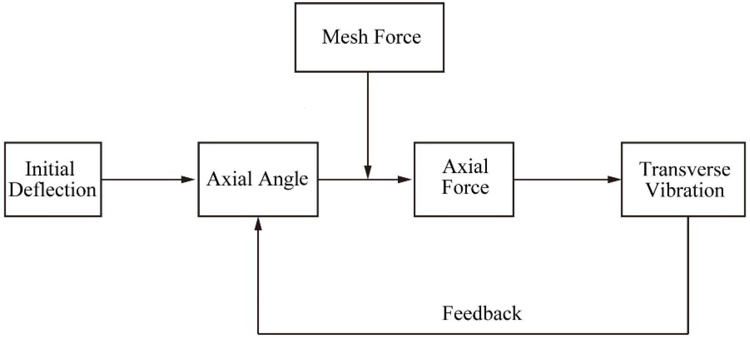
For a pair of precise meshing spur gears, there is no axial force when they are running, so only torsional vibration can occur. Therefore, there must be an axial force that could excite the transverse vibration and results in fatigue failure. Actually, the gears used in industry cannot be precisely meshed as expected. The deflections of axes can create an angle between the contact line of the gears and the rotation axis. As a result, an axial force component is contained in the mesh force vector, and it can become a self-excited force of the system. This kind of axial force can excite transverse vibrations of the gear. Once the vibration status changes, the axial force changes accordingly, and subsequently the changed axial force will, in turn, continue to affect the transverse vibration. This consecutive interaction will be enhanced when the feedback is positive, and the gear system will constitute a self-excited vibration system.
Figure 1 depicts a schematic diagram of the mechanism of gear self-excited vibration. Through the axial force and the damping force applied to the transverse traveling wave vibration, the change in the system energy can be determined. If the excitation work is more than the work consumed by the damping, the system energy increases, which indicates that self-excited gear vibration will occur. This is the theory upon which the analysis of this paper is based.
2.1. Traveling Wave Vibration of the Rotating Gear
A cylindrical coordinate (r, θ, z) fixed on the rotating gear is defined, and in order to describe the theoretical analysis as well as the subsequent numerical results more clearly, the phenomenon of the traveling wave vibration of the thin rotating gear is discussed first.
The transverse vibration of a thin spur gear has the same expressions as the circular plate, since it is usually simplified as an annular plate. According to the plate vibration theory, displacement of the circular plate transverse vibration could be expressed as:
where w is the vibration displacement in the z direction, r is the radial coordinate, θ is the circumferential coordinates, t is time, A is the vibration amplitude that depends on the radial coordinate r, m is the number of nodal diameters, and ω is the vibration frequency.
Equation (1) is the vibration displacement of a stationary gear or the displacement in the rotary coordinate fixed on the rotating gear. It can also be decomposed into two components:
Since the gear is rotating, the rotation speeds of the nodal diameters are different in the inertia coordinate for these two components; therefore, the transverse vibration of a rotating gear is a kind of traveling wave vibration. The first component of the right item of Equation (2) represents a traveling wave rotating in the same direction of the gear, which is called the forward traveling wave (FTW), whereas the second component represents a traveling wave rotating in the opposite direction of the gear, called the backward traveling wave (BTW).
2.2. Mechanical Model of the Gear Self-Excited Force
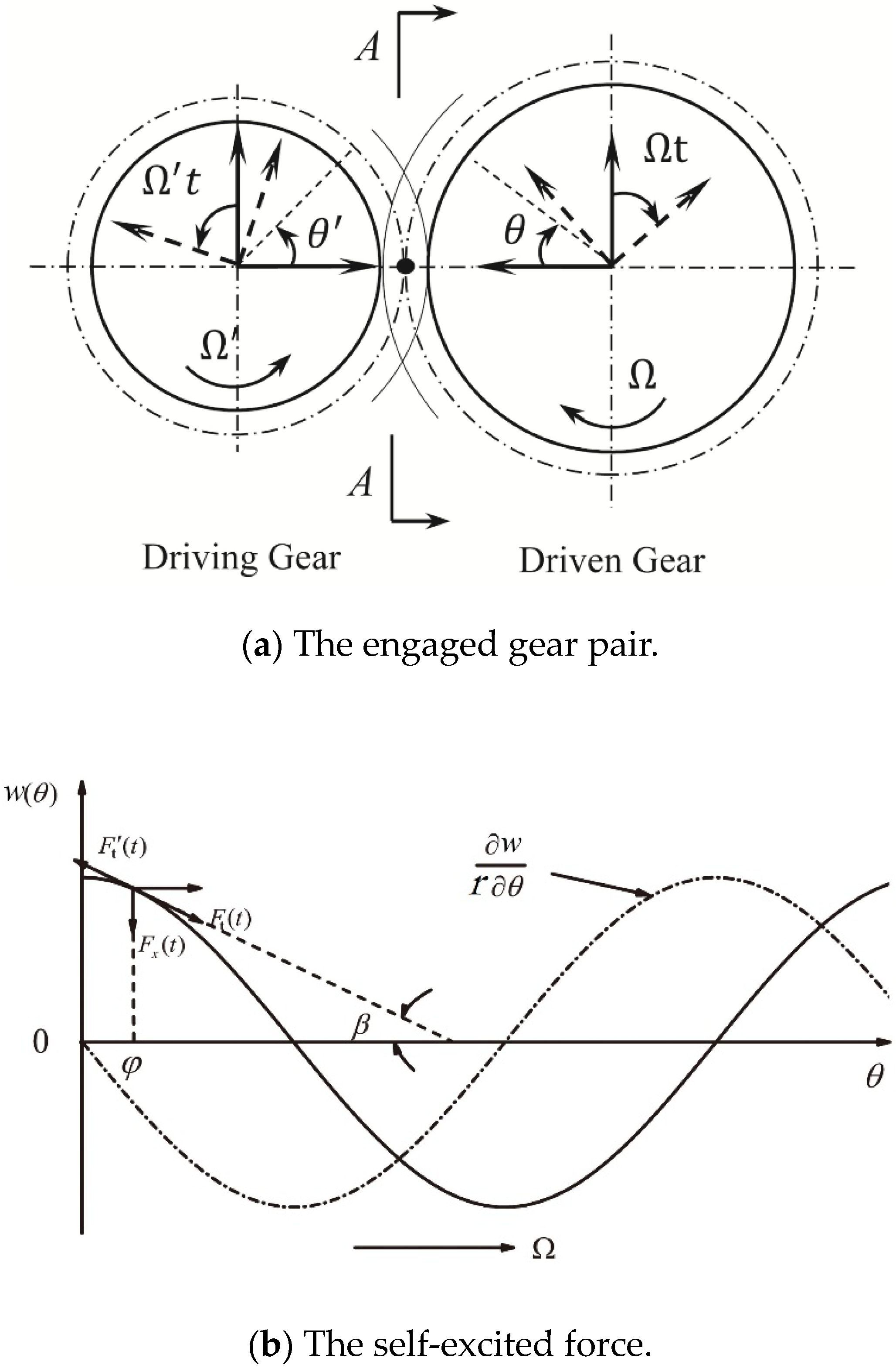
According to the gear self-excited vibration mechanism, a mechanical model is proposed to describe the self-excited force of the spur gear. Figure 2a is the schematic diagram of an engaged spur gear pair and the defined rotary coordinates. If there is an initial axial deflection when the gears are running, the normal direction of the surface of the action is no longer perpendicular to the rotation axis, and there occurs transverse deformation along the tangential direction at the mesh point, as shown in Figure 2b. Thus, the mesh force will generate an axial component—the gear self-excited force Fz(t).
If the transverse vibration displacement at the gear rim develops along the circumferential direction, the displacement is approximately along a cosine curve, shown as the solid line in Figure 2b when looking from the A-A direction. According to the relationship between the forces shown in Figure 2b, and taking the direction of w(θ) as the positive direction, the self-excited force can be expressed as:
where β is the axial angle that represents the angle between the normal direction and the axial direction of the meshing force.
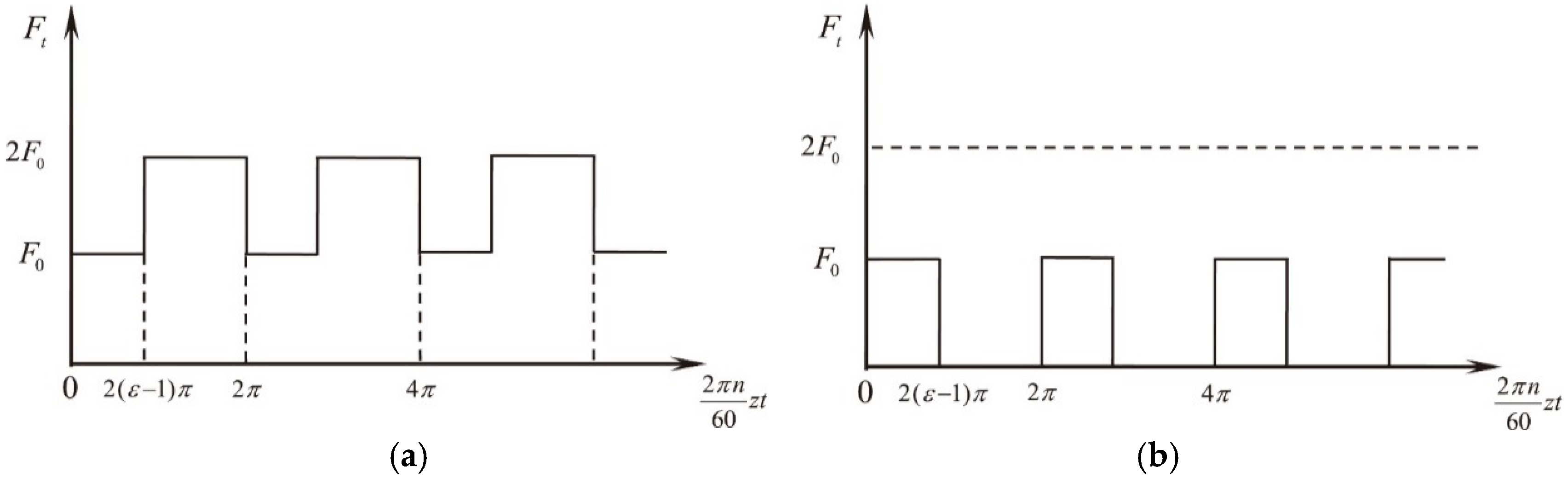
Based on the mechanism of the gear meshing, the engagement process of the gears with contact ratios from 1–2 consists of two parts: The single tooth mesh process and the double teeth mesh process. If the gear torque load is T0, take the pitch diameter d0 instead of the mesh point diameter d1, assuming that the height of the gear tooth is small enough compared to the gear diameter. Accordingly, the mesh force Ft(t) for the engaged gear can be expressed as:
Since the engagement of the operating gear is a continuous process, the single tooth and the double tooth mesh processes are converting to each other continually. So, the mesh force Ft(t) is not only time-dependent when observed from the whole gear, but is also periodic. Thus, two different mesh points should be considered.
Let F0 = 2T0/d0, and after the coordinate transformation t′ = 2πnzt/60, the expressions of the mesh force at mesh point 1 and mesh point 2 are shown in Figure 3, where n is the rotational speed, z is the number of gear teeth, and ε is the gear contact ratio.
Figure 3 shows that both forces are periodic functions with a period time of 2π. To facilitate further analysis, Fourier expansion of these two mesh forces in one period is completed, and the harmonic terms of the mesh forces are:
where k is excitation order.
Substitute Equation (5) into Equation (3), then the expression of the self-excited force can be obtained.
Although the mechanical model of the self-excited force proposed here is simple, it meets all of the requirements of the mechanical principles. Thus, the mechanical model is sufficient to describe the overall behavior of gear.
2.3. The Work of the Self-Excited Force on the Vibration
Take the backward traveling wave of the driven gear as an example. The position angle θ of the mesh point varies with time in the rotary coordinate, and the relationship between θ and time t (θ = 0 when t = 0) is:
where Ω is the gear angular speed.
In addition, mesh points 1 and 2 are on the two adjacent teeth, and the phase between these two points is shown in Figure 4. In an actual situation, the phase changes as the engagement process continues. However, in order to simplify the analysis, let . Then, the expressions of the backward traveling wave at mesh point 1 and mesh point 2 are:
Therefore, the work done by the additional force to the backward traveling wave during one vibration cycle can be determined by the following equation:
The time of one vibration cycle for the backward traveling wave is T = 2π/ω. If we substitute Equation (5) into Equation (9), then the excitation work done to the BTW is:
where
And
The excitation work for the forward traveling wave vibration can be quickly obtained by simply replacing wb with wf in Equation (9) and the other related equations. Moreover, if the object of the analysis is the driving gear, the term Ft(t) must be replaced with −Ft(t). That is, the relationship of the excitation work between the driving gear and the driven gear is:
2.4. The Work of the Damping Force on the Vibration
The damping of an engaged rotating gear is quite complex and hard to calculate. However, because the damping always dissipates the energy, the work of the damping force could be obtained by taking advantage of the loss factor η, which represents the energy loss of the system caused by the damping effect [32]. The definition is:
where ΔU is the energy dissipated of the system during one damping cycle (vibration cycle) and Umax is the initial system energy, which is approximately equal to the maximum system kinetic energy when the damping is relatively low, which is Umax = Tmax.
For an engaged gear, the maximum kinetic energy is the integration of the kinetic energy throughout the whole gear web, which is:
where A(r) = A0·R(r). According to Equations (18) and (19), and the relationship η = 2ζ for the situation of low damping [32], the damping work during one vibration cycle can be determined as:
where the term can be calculated from the deformation results of the FEM modal analysis:
where num is the number of the numerical integration data, and ri and R(i) are the values of the radius and normalized deformation at point i, respectively.
2.5. Theoretical Prediction of the Self-Excited Vibration
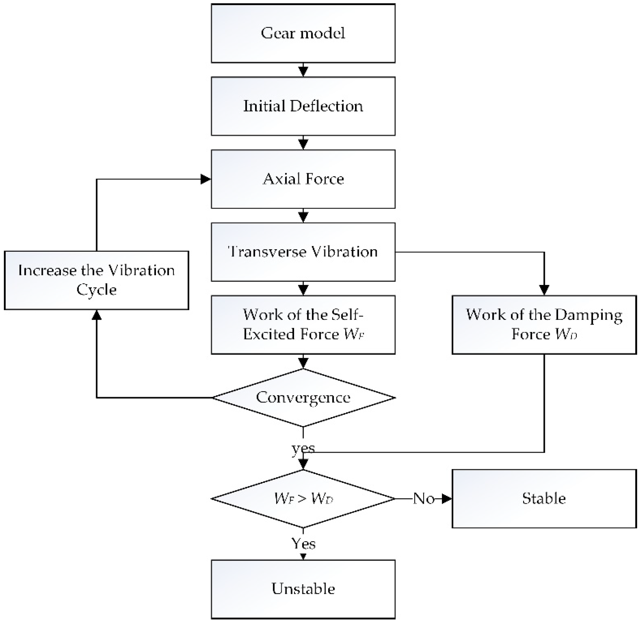
From the perspective of the system energy, if the excitation work applied to the traveling waves is larger than the damping work, the total energy of the system will increase over time, indicating that self-excited vibration will occur. Thus the condition of the gear self-excited vibration occurrence is:
The mesh force amplitude F0 when the self-excited vibration occurs can then be determined by solving the equation:
Moreover, once the mesh force amplitude F0 is obtained, the critical transmission power, which also represents the minimum transmission power that can cause self-excited vibration, or the maximum transmission power for safe operation, can then be predicted according to the definition of the transmission power.
Therefore, if the actual operation transmission power P is larger than the critical transmission power P0, then self-excited vibration will occur and the system will be unstable.
3. Results and Discussion
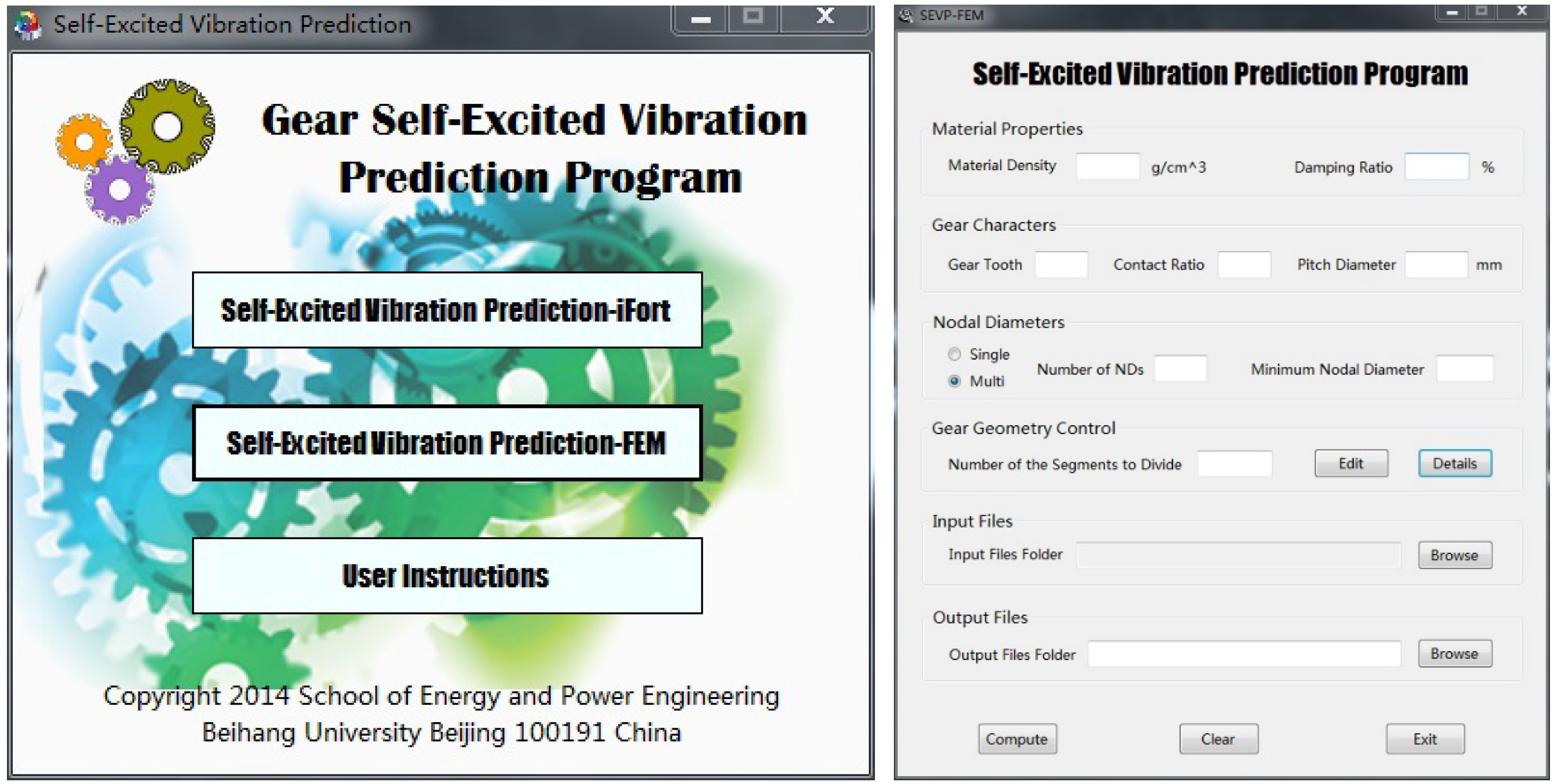
According to the theoretical analysis of self-excited vibration in thin spur gears, the calculation program of the proposed method is developed by using Fortran language. The block diagram of proposed analysis method is shown in Figure 5. And the interface of the program is shown in Figure 6.
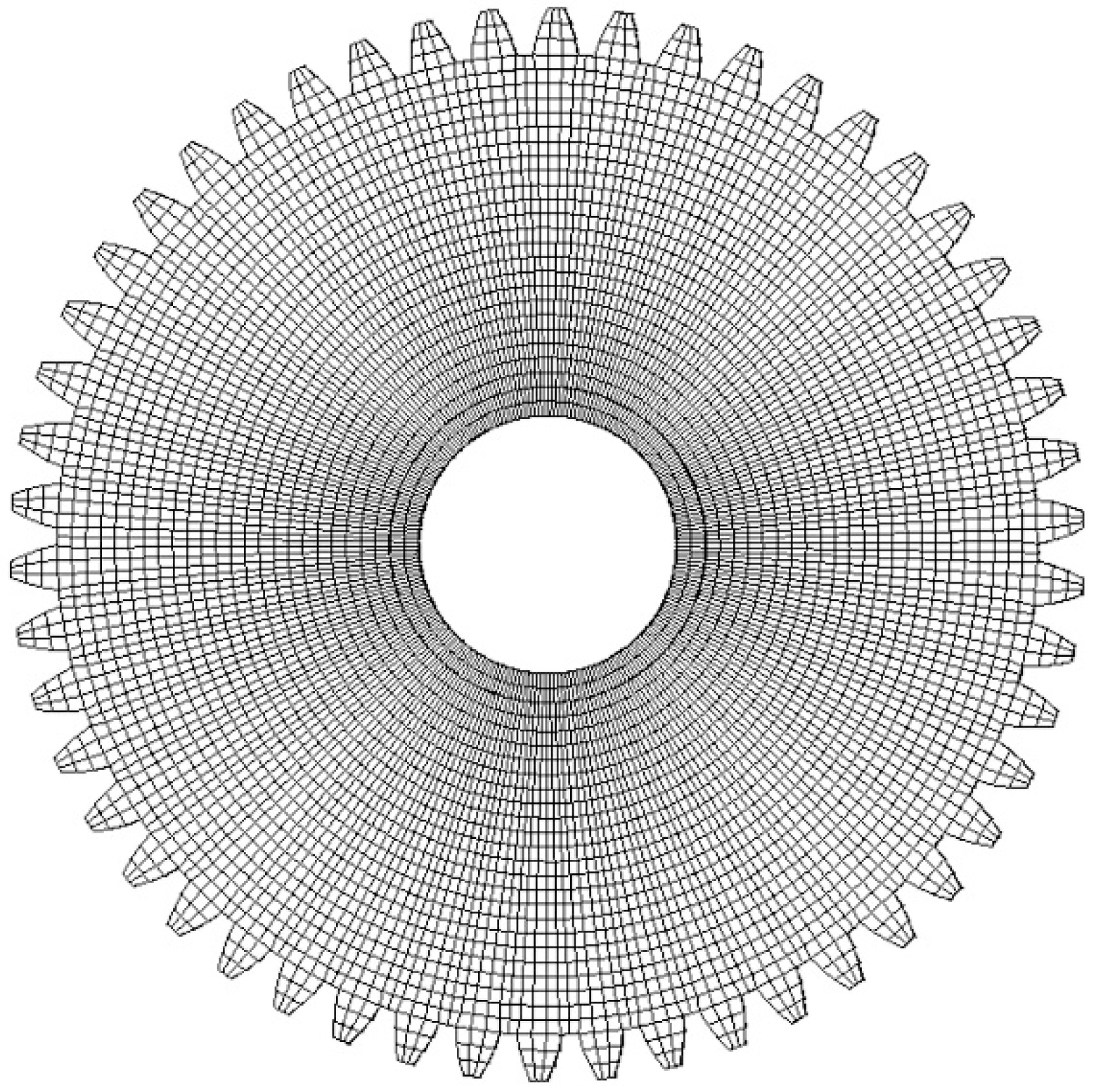
The program shown in this paper is applied to a model of a virtual thin spur gear. The parameters of the thin spur gear used in this numerical simulation are listed in Table 1, with radius of the rim r1 = 95 mm, radius of the hole r2 = 25 mm, thickness h = 4 mm, and the number of teeth z = 50. The finite element model is shown in Figure 7. The gear material properties are: Young modulus E = 212 GPa, density ρ = 7.85 × 10³ kg/m3, and Poisson’s ratio μ = 0.284. Several different parameters were also chosen for the numerical simulation in order to demonstrate the effects of the nodal diameter and damping ratio on the self-excited vibration stability. The maximum simulation speed was 10,000 rpm, and the results for each speed were calculated.
3.1. Convergence Analyses
For high-speed gears, the meshing period is smaller than the low nodal diameter’ vibration period. For the convenience of calculation, the initial moment of the vibration period during the calculation is defined as the initial moment of the single-tooth engagement period, or the initial moment of the double-tooth engagement. A vibration cycle consists of a number of complete engagement cycles and an incomplete engagement cycles. In the program, the incomplete engagement cycle is treated as the truncation error. Therefore, the greater vibration cycle considered during the calculation, the smaller the truncation error. Figure 8 shows the impact of the calculation cycle on the results. When the vibration cycle is 1, the numerical calculation results have a certain degree of fluctuation. When the vibration cycle is large enough (more than 100), the work done by the excitation force becomes stabilized and approaches the limit value. Therefore, in the calculation below, the vibration cycle is selected as 100.
3.2. Stability Boundary Analysis
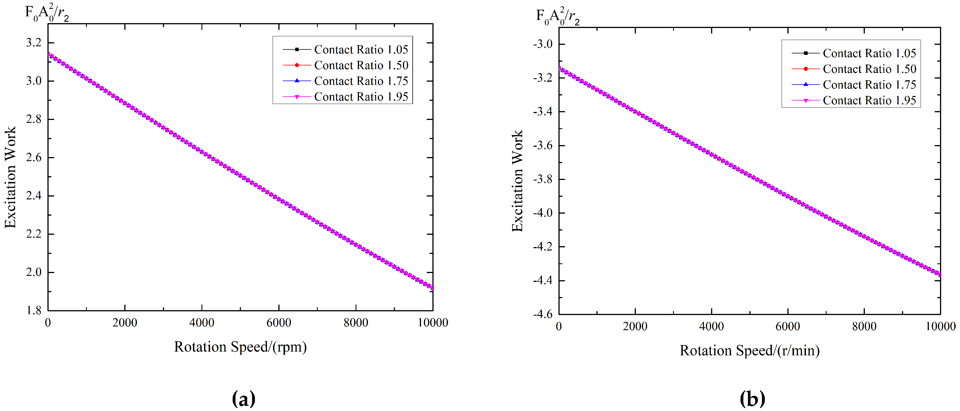
Figure 9 provides an example of the excitation work done to the BTW and FTW vibrations of the driven gear with two nodal diameters. The most obvious difference between the BTW and FTW is that the excitation work done to the BTW is positive, whereas the excitation work done to the FTW is negative. This means the self-excited force promotes the vibration of the BTW and decreases the vibration of the FTW. In this circumstance, the vibration energy of the BTW increases over time if there is insufficient damping, which indicates that self-excited vibration may occur. On the other hand, self-excited vibration cannot occur for the FTW vibration because of the negative excitation work, which means that the self-excited force consumes the vibration energy, behaving like damping. For the driving gear, since the excitation work done to the traveling waves is opposite to that of the driven gear, self-excited vibration will occur in the FTW vibration rather than the BTW vibration.
The vibrations with three, four, and five nodal diameters have the same conclusions, and the figures will not be superfluously presented here. The rest of the discussion in this paper is based on the results of the backward traveling wave vibration of the driven gear as an example.
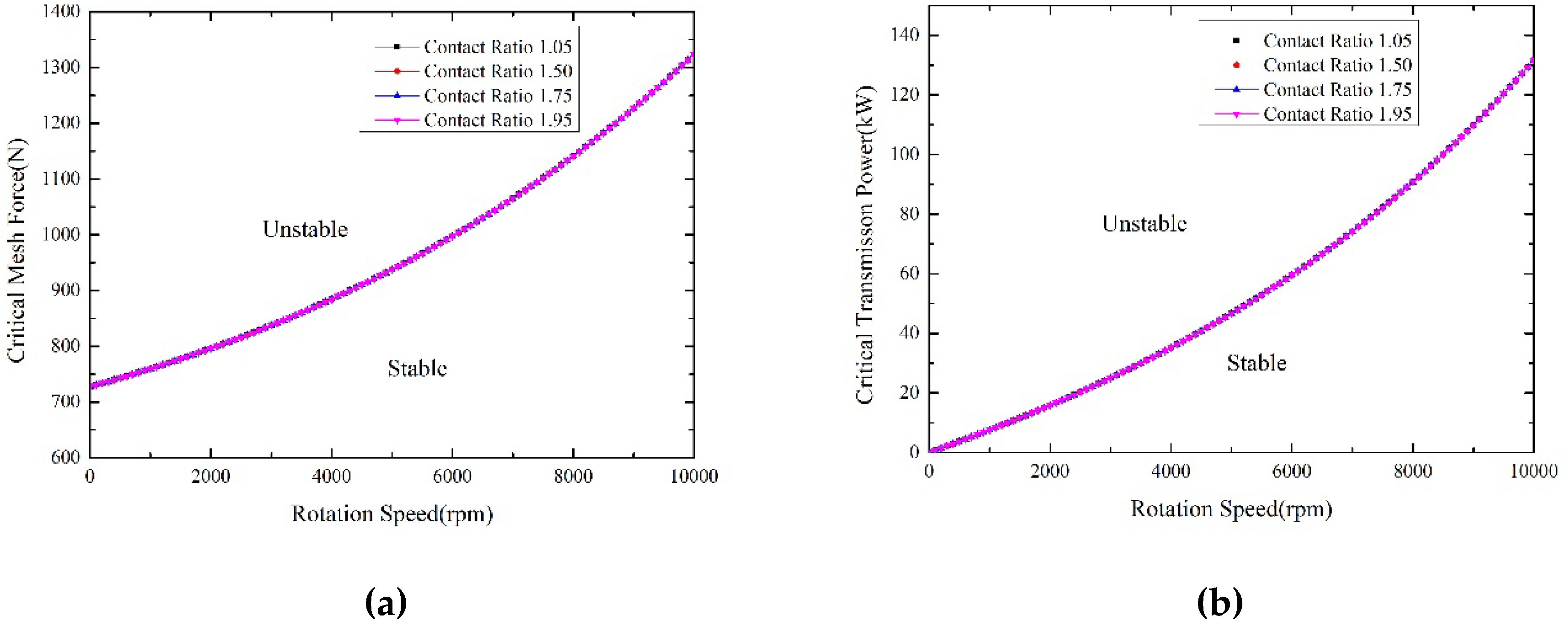
Figure 10 depicts the amplitude of the mesh force and the transmission power for the vibration with three nodal diameters when self-excited vibration occurs, which are called the critical mesh force and the critical transmission power, respectively. For each of the vibration parameters, e.g., nodal diameter and contact ratio, the entire image region is divided into two parts by the value line: An unstable area and a stable area. That means if the operating point is within the unstable area, then self-excited vibration will occur, and the gear will become unstable. Therefore, the possibility of self-excited vibration occurrence for thin spur gears indeed exists, and the size of the stable area determines the stability of the gear’s self-excited vibration. Figure 10 shows that the stable area is not affected by the contact ratio.
In order to analyze the influences of the number of nodal diameters and the damping ratio on the stability of the gear system, some additional comparisons between different nodal diameters, as well as damping ratios, are completed.
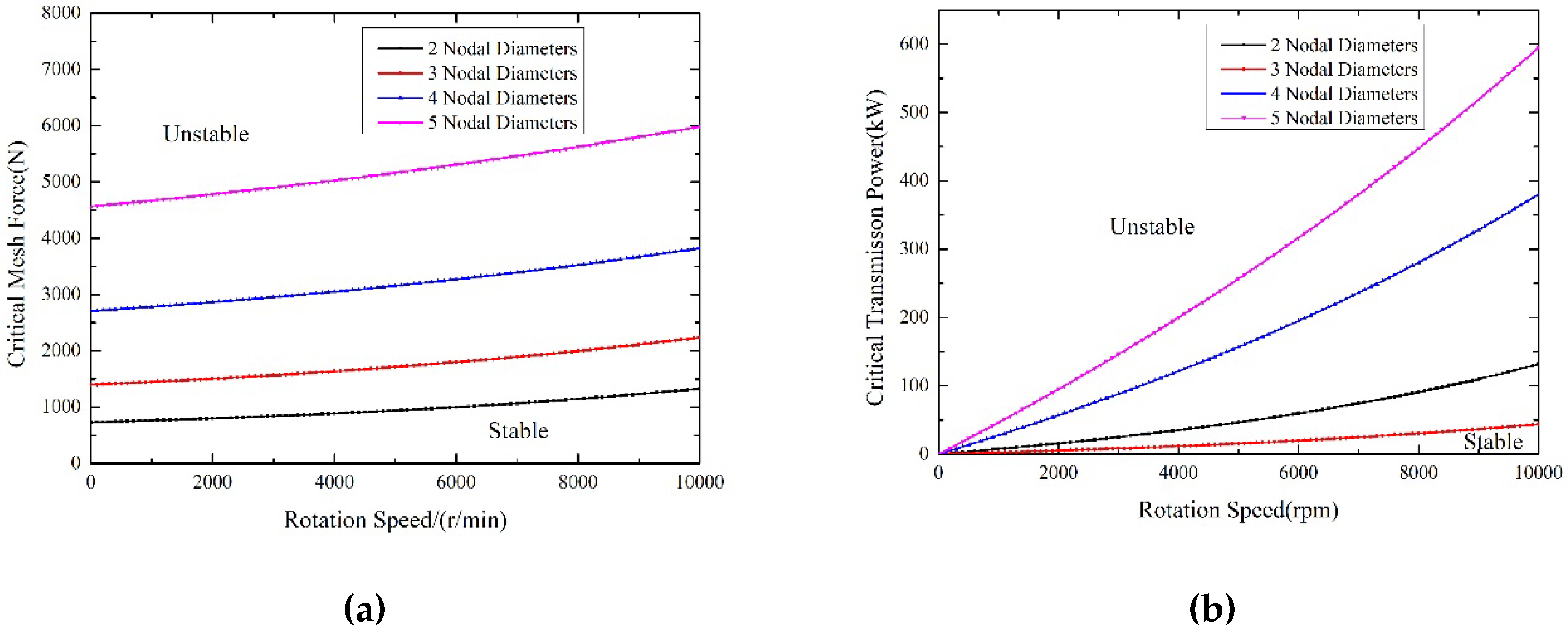
Figure 11 shows the critical mesh force and critical transmission power for vibrations with different nodal diameters. From the figure, we conclude that the number of nodal diameters considerably affects both the critical mesh force and critical transmission power. The more the number of nodal diameters, the larger the stable area. This is because a vibration with more nodal diameters always has a higher vibration frequency. As a result, the maximum vibration velocity, as well as the maximum kinetic energy of the system, are greater than those vibrations of the smaller nodal diameters, resulting in larger damping work for the same damping ratio. Thus, through the discussions above, we conclude that when the other conditions are constant, the vibration with fewer nodal diameters more easily creates self-excited vibration and becomes unstable.
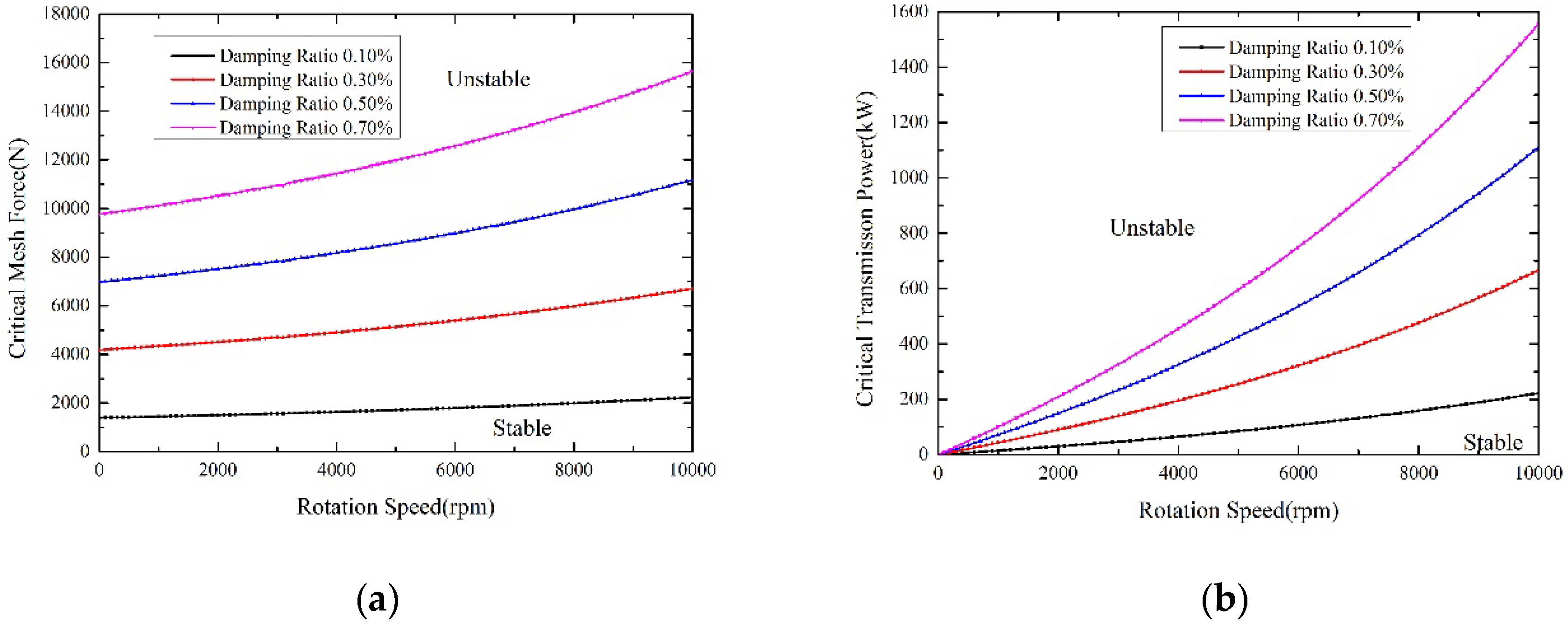
Figure 12 shows the critical mesh force and critical transmission power for vibrations with different damping ratios. The results show that the damping ratio influences both the critical mesh force and critical transmission power. In fact, according to Equation (20), the capacity of the gear stability linearly increased along with the increase of the damping ratio. Therefore, increasing the damping ratio is one of the most effective methods to improve the stability and avoid self-excited vibration for the selected gear operating condition.
The results for the driving gear are similar to those of the driven gear discussed above, and are not present in this paper.
4. Conclusions
This paper addresses the self-excited vibration of a thin spur gear caused by the initial transverse vibration. Based on the theory of self-excited vibration, a method is proposed to predict the condition of the self-excited vibration occurrence and the capacity of the self-excited vibration stability for a thin spur gear. The self-exciting force and the associated excitation and damping work are analyzed theoretically, and a numerical simulation is performed to verify the theoretical analysis. The operating conditions when the self-excited vibration occurs are predicted, and the influences of the nodal diameter, contact ratio, and damping ratio on the gear stability are also discussed. The results from the numerical simulation prove that the proposed method is capable of predicting the stability of the gear system and several main conclusions from the simulation are drawn as follows:
(1) The additional axial force caused by the initial transverse vibration is the self-exciting force of the gear system, which promotes backward traveling wave vibration of the driven gear and forward traveling wave vibration of the driving gear. That means self-excited vibration may occur under these cases.
(2) The effect of the contact ratio on the excitation work and the stability can be neglected. The contact ratio is not a key parameter that affects the self-excited vibration of the gear.
(3) The nodal diameter significantly influences both the critical mesh force and critical transmission power, which represent the capacity for stability, indicating that the vibration with a smaller nodal diameter would more easily encounter self-excited vibration.
(4) The damping ratio also has a significant impact on system stability. Increasing the damping ratio is the most effective method for improving the stability and avoiding self-excited vibration for a selected operating condition for the gear system.
As the method proposed in this paper can predict self-excited vibration in spur gears, it is useful for troubleshooting the transmission box, especially for those with thin gears. The method can also be applied in industry for the analysis of gear crack failures with non-resonance conditions.
Author Contributions
Conceptualization and Methodology, Y.W. Software development and data analysis, L.Y. and H.Y. Writing—Original Draft Preparation, H.Y. Review and Editing, A.T.
Funding
This work was supported by the National Nature Science Foundation of China (No. 51475022).
Conflicts of Interest
The authors declare no conflict of interest.
Notation
| A(r) | vibration deformation of gear web | Umax | initial system energy |
| A0 | vibration amplitude at the gear rim | w | vibration displacement |
| BTW | backward traveling wave | wf | displacement of FTW |
| d0 | pitch diameter | wb | displacement of BTW |
| d1 | diameter of mesh point | W1cbF | excitation work of BTW at mesh point 1 |
| Ft(t) | mesh force | W2cbF | excitation work of BTW at mesh point 2 |
| F0 | amplitude of the mesh force | WcbF | excitation work of BTW for driven gear |
| Fz(t) | self-excited force of driven gear | WzbF | excitation work of BTW for driving gear |
| FTW | forward traveling wave | WF | excitation work |
| h | thickness of the gear web | WD | damping work |
| k | excitation order | β | axial angle |
| m | number of nodal diameters | β′ | central angle of one gear tooth |
| n | rotational speed (r/min) | ΔU | energy dissipated in one damping cycle |
| P0 | transmission power | ε | contact ratio |
| r | radius of the gear | phase angle between adjacent teeth | |
| R(r) | normalized deformation function | φ | circumferential angle of the mesh point |
| r1 | radius of the inner hole | η | loss factor |
| r2 | radius of the gear rim | Ω | angular speed of the gear |
| Tmax | maximum kinetic of the gear | θ | circumferential coordinates |
| T0 | torque | ζ | damping ratio |
References
- Byrtus, M.; Zeman, V. On modeling and vibration of gear drives influenced by nonlinear couplings. Mech. Mach. Theory 2011, 46, 375–397. [Google Scholar] [CrossRef]
- Hosseini-Hashemi, S.; Es’Haghi, M.; Taher, H.R.D.; Fadaie, M. Exact closed-form frequency equations for thick circular plates using a third-order shear deformation theory. J. Sound Vib. 2010, 329, 3382–3396. [Google Scholar] [CrossRef]
- Leissa, A.W. Vibration of Plates; Report Number: NASA SP-160; NASA: Washington, DC, USA, 1969; pp. 7–36.
- Nevzat Özgüven, H.; Houser, D.R. Mathematical models used in gear dynamics—a review. J. Sound Vib. 1988, 121, 383–411. [Google Scholar] [CrossRef]
- Sinha, S.K. Free vibrations of a thick spinning annular disk with distributed masses at the outer edge. J. Sound Vib. 1988, 122, 217–231. [Google Scholar] [CrossRef]
- Sinha, S.K. On free vibrations of a thin spinning disk stiffened with an outer reinforcing ring. J. Vib. Acoust. Stress Reliab. 1988, 110, 507–514. [Google Scholar] [CrossRef]
- Cote, A.; Atalla, N.; Nicolas, J. Effects of shear deformation and rotary inertia on the free vibration of a rotating annular plate. J. Vib. Acoust. 1997, 119, 641–643. [Google Scholar] [CrossRef]
- Suzuki, K.; Yoshida, H.; Zheng, X. Influence of initial tension on out-plane vibrations of a rotating circular plate: Advanced in dynamics and design of continuous systems. JSME Int. J. Ser. C-Mech. Syst. Mach. Elem. Manuf. 2002, 45, 54–59. [Google Scholar] [CrossRef]
- Chen, Y.R.; Chen, L.W. Vibration and stability of rotating polar orthotropic sandwich annular plates with a viscoelastic core layer. Compos. Struct. 2007, 78, 45–57. [Google Scholar] [CrossRef]
- Drago, R.J.; Brown, F.W. The analytical and experimental evaluation of resonant response in high-speed, lightweight, highly loaded gearing. J. Mech. Des. 1981, 103, 346–356. [Google Scholar] [CrossRef]
- Li, S. Experimental investigation and FEM analysis of resonance frequency behavior of three dimensional, thin-walled spur gears with a power-circulating test rig. Mech. Mach. Theory 2008, 43, 934–963. [Google Scholar] [CrossRef]
- Bogacz, R.; Noga, S. Free transverse vibration analysis of a toothed gear. J. Arch. Appl. Mech. 2012, 82, 1159–1168. [Google Scholar] [CrossRef]
- Qin, H.; Lu, M.; She, Y.; Wang, S.; Li, X. Modeling and solving for transverse vibration of gear with variational thickness. J. Cent. South Univ. 2013, 20, 2124–2133. [Google Scholar] [CrossRef]
- Honda, Y.; Matsuhisa, H.; Sato, S. Modal response of a disk to a moving concentrated harmonic force. J. Sound Vib. 1985, 102, 457–472. [Google Scholar] [CrossRef]
- Ouyang, H.; Mottershead, J.E. Unstable travelling waves in the friction-induced vibration of discs. J. Sound Vib. 2001, 248, 768–779. [Google Scholar] [CrossRef]
- Lee, C.W.; Kim, M.E. Separation and identification of travelling wave modes in rotating disk via directional spectral analysis. J. Sound Vib. 1995, 187, 851–864. [Google Scholar] [CrossRef]
- Tian, J.; Hutton, S.G. Traveling-wave modal identification based on forced or self-excited resonance for rotating discs. J. Vib. Control 2001, 7, 3–18. [Google Scholar] [CrossRef]
- Parker, R.G.; Vijayakar, S.M.; Imajo, T. Non-linear dynamic response of a spur gear pair: Modelling and experimental comparisons. J. Sound Vib. 2000, 237, 435–455. [Google Scholar] [CrossRef]
- Tamminana, V.K.; Kahraman, A.; Vijayakar, S. A study of the relationship between the dynamic factors and the dynamic transmission error of spur gear pairs. J. Mech. Des. 2006, 129, 75–84. [Google Scholar] [CrossRef]
- Oliveri, L.; Rosso, C.; Zucca, S. Influence of actual static transmission error and contact ratio on gear engagement dynamics. In Proceedings of the 35th IMAC, A Conference and Exposition on Structural Dynamics, Garden Grove, CA, USA, 30 January–2 February 2016. [Google Scholar]
- Liu, Z.X.; Liu, Z.S.; Zhao, J.M.; Zhang, G.H. Study on interactions between tooth backlash and journal bearing clearance nonlinearity in spur gear pair system. Mech. Mach. Theory 2017, 107, 229–245. [Google Scholar] [CrossRef]
- Wei, J.; Bai, P.X.; Qin, D.T.; Lim, T.C.; Yang, P.W.; Zhang, H. Study on vibration characteristics of fan shaft of geared turbofan Engine with sudden imbalance caused by blade off. J. Vib. Acoust. 2018, 140, 041010. [Google Scholar] [CrossRef]
- Liu, F.H.; Jiang, H.J.; Liu, S.N.; Yu, X.H. Dynamic behavior analysis of spur gears with constant & variable excitations considering sliding friction influence. J. Mech. Sci. Technol. 2016, 30, 5363–5370. [Google Scholar] [CrossRef]
- Rosso, C.; Bonisoli, E. An unified framework for studying gear dynamics through model reduction techniques. In Proceedings of the 34th IMAC, A Conference and Exposition on Structural Dynamics, Orlando, FL, USA, 25–28 January 2016. [Google Scholar]
- Hotait, M.A.; Kahraman, A. Experiments on the relationship between the dynamic transmission error and the dynamic stress factor of spur gear pairs. Mech. Mach. Theory 2013, 70, 116–128. [Google Scholar] [CrossRef]
- Moss, J.; Kahraman, A.; Wink, C. An experimental study of influence of lubrication methods on efficiency and contact fatigue life of spur gears. J. Tribol. 2018, 140, 051103. [Google Scholar] [CrossRef]
- Talbot, D.; Sun, A.; Kahraman, A. Impact of tooth indexing errors on dynamic factors of spur gears: Experiments and model simulations. J. Mech. Des. 2016, 138, 093302. [Google Scholar] [CrossRef]
- Costantino, C.; Paola, F.; Gabriele, M.; Giovanni, D.C. Numerical investigation on traveling wave vibration of bevel gears. In Proceedings of the ASME 2007 International Design Engineering Technical Conferences Computers and Information in Engineering Conference, Las Vegas, NV, USA, 4–7 September 2007. [Google Scholar]
- Bucher, I. Estimating the ratio between travelling and standing vibration waves under nonstationary conditions. J. Sound Vib. 2004, 270, 341–359. [Google Scholar] [CrossRef]
- Talbert, P.B.; Gockel, R.R. Modulation of gear tooth loading due to traveling wave vibration. In Proceedings of the ASME 2003 International Design Engineering Technical Conferences and Computers and Information in Engineering Conference, Chicago, IL, USA, 2–6 September 2003. [Google Scholar]
- Yang, L.; Wang, Y.R. Prediction on self-excited vibration of thin spur gear based on energy method. J. Aerospace Power 2016, 31, 241–248. (In Chinese) [Google Scholar] [CrossRef]
- De Silva, C.W. Vibration Damping, Control, and Design, 3rd ed.; CRC Press: Boca Raton, FL, USA, 2007; ISBN 978-142-005-321-0. [Google Scholar]
Figure 1.
The mechanism of the gear self-excited vibration.

Figure 2.
Schematic diagram of the engaged gear pair and the self-excited force.

Figure 3.
Expressions of the mesh force: (a) Mesh point 1, and (b) mesh point 2. The abscissa indicates time, and the ordinate indicates the meshing force.
Figure 3.
Expressions of the mesh force: (a) Mesh point 1, and (b) mesh point 2. The abscissa indicates time, and the ordinate indicates the meshing force.

Figure 4.
Schematic diagram of the phase between the two mesh points.

Figure 5.
The block diagram of proposed analysis method.

Figure 6.
The interface of the program.

Figure 7.
Finite element model (FEM) of the gear.

Figure 8.
The impact of the calculation cycle on the results.

Figure 9.
Excitation work of the vibration with two nodal diameters: (a) Backward traveling wave (BTW) and (b) forward traveling wave (FTW).
Figure 9.
Excitation work of the vibration with two nodal diameters: (a) Backward traveling wave (BTW) and (b) forward traveling wave (FTW).

Figure 10.
(a) Critical mesh force and (b) critical transmission power for the vibration with three nodal diameters.
Figure 10.
(a) Critical mesh force and (b) critical transmission power for the vibration with three nodal diameters.

Figure 11.
Influences of the nodal diameters: (a) Critical mesh force and (b) critical transmission power.
Figure 11.
Influences of the nodal diameters: (a) Critical mesh force and (b) critical transmission power.

Figure 12.
Influences of the damping ratios, m = 3, ε = 1.75 for (a) critical mesh force and (b) critical transmission power.
Figure 12.
Influences of the damping ratios, m = 3, ε = 1.75 for (a) critical mesh force and (b) critical transmission power.


Table 1.
Gear parameters.
| Parameter | Value |
|---|---|
| r1 | 25 mm |
| r2 | 95 mm |
| h | 4 mm |
| z | 50 |
© 2018 by the authors. Licensee MDPI, Basel, Switzerland. This article is an open access article distributed under the terms and conditions of the Creative Commons Attribution (CC BY) license (http://creativecommons.org/licenses/by/4.0/).
Share and Cite
MDPI and ACS Style
Wang, Y.; Ye, H.; Yang, L.; Tian, A. On the Existence of Self-Excited Vibration in Thin Spur Gears: A Theoretical Model for the Estimation of Damping by the Energy Method. Symmetry 2018, 10, 664. https://doi.org/10.3390/sym10120664
AMA Style
Wang Y, Ye H, Yang L, Tian A. On the Existence of Self-Excited Vibration in Thin Spur Gears: A Theoretical Model for the Estimation of Damping by the Energy Method. Symmetry. 2018; 10(12):664. https://doi.org/10.3390/sym10120664
Chicago/Turabian StyleWang, Yanrong, Hang Ye, Long Yang, and Aimei Tian. 2018. "On the Existence of Self-Excited Vibration in Thin Spur Gears: A Theoretical Model for the Estimation of Damping by the Energy Method" Symmetry 10, no. 12: 664. https://doi.org/10.3390/sym10120664
Note that from the first issue of 2016, this journal uses article numbers instead of page numbers. See further details here.